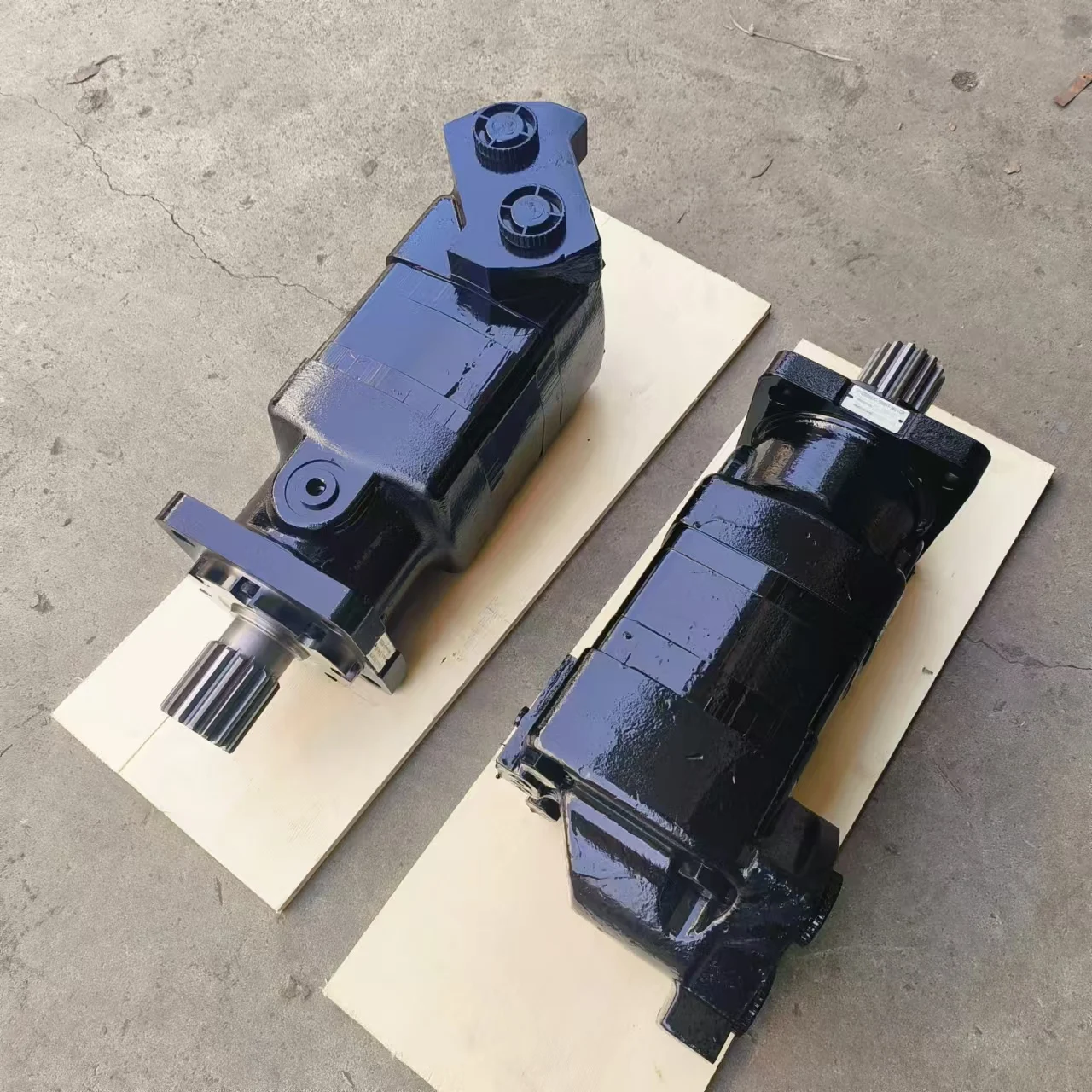
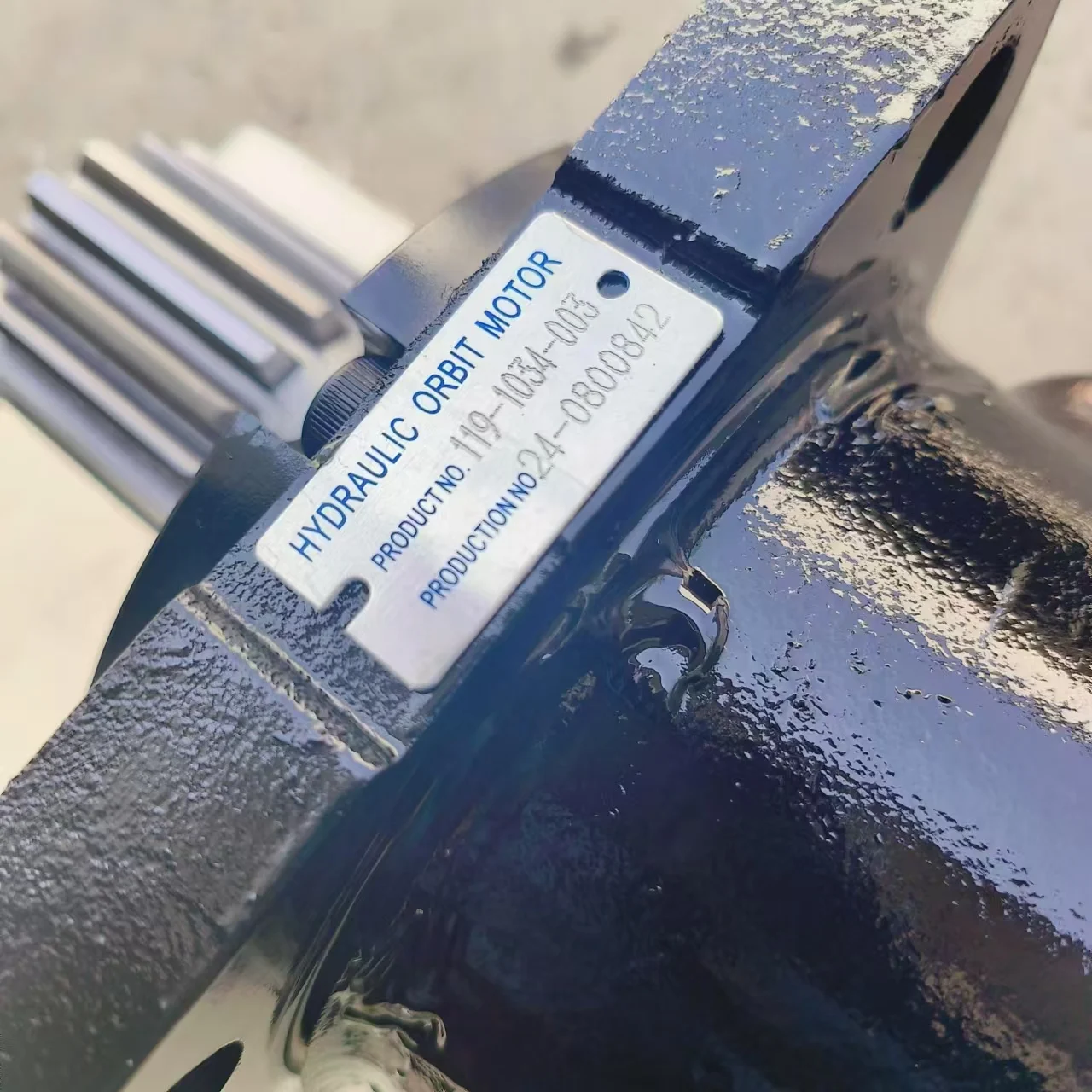
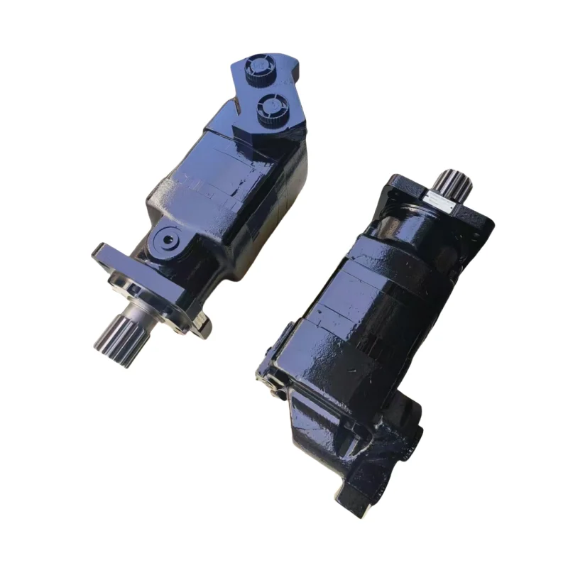
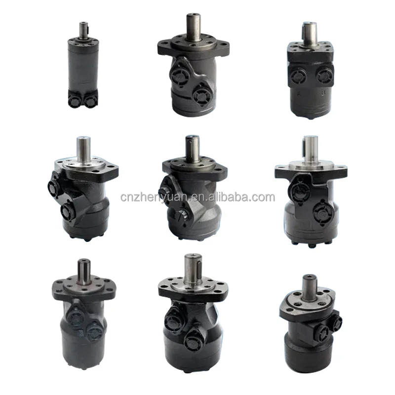

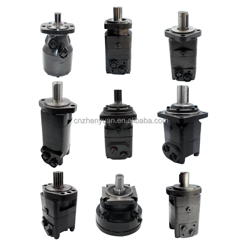

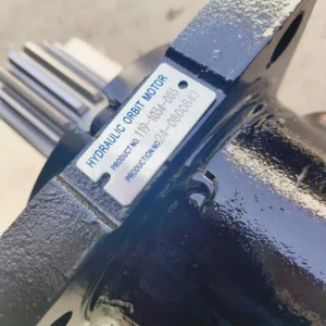

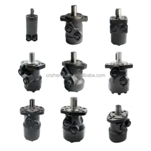
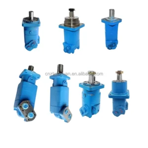
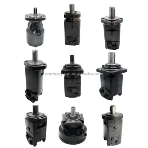
MT400C03120 Hydraulic orbit Motor BM4 BMT/OMT/MT/OMR 160/200/230/250/315/400/500/630/800 High Pressure Piston Motor
Core performance parameters
– Motor type: Internal meshing cycloidal pinwheel motor, right rotation direction, fixed displacement design, adopts end face distribution structure, suitable for medium and high-pressure hydraulic systems, providing low-speed and high-torque power output for heavy-duty actuators.
– Displacement and pressure parameters: Rated displacement 400 mL/r; Rated working pressure: 25 MPa, maximum allowable pressure: 31.5 MPa (short-term ≤10 seconds); Rated speed: 200 r/min, minimum stable speed: 3 r/min (no crawling), maximum speed: 300 r/min (short time ≤5 minutes).
Torque and efficiency parameters: Rated torque 1590 N·m, maximum output torque 2000 N·m (at the highest pressure); Volumetric efficiency ≥90%, total efficiency ≥85%; The rotational speed fluctuation is ≤±2%, and the torque stability is ±2% when the load changes.
– Operating characteristics: Continuous operating oil temperature ≤85℃, rated working condition return oil back pressure ≤3 MPa; Noise value ≤85 dB (measured at 1 meter); The fault-free operating life under rated conditions is ≥ 12,000 hours.
2. Structure and connection parameters
– Structural type: Internal meshing cycloidal pinwheel structure, integrating cycloidal rotor, pinwheel stator, end face distribution plate, output shaft and built-in check valve; It adopts an integral cast iron housing, is equipped with roller bearings (capable of withstanding radial and axial combined loads), and supports mechanical braking interfaces.
– Core material: The cycloidal rotor is made of alloy steel (quenched and tempered, hardness HRC52-55); The stator of the needle wheel is made of bearing steel GCr15 (quenched treatment, hardness HRC60-63). The distribution plate is made of copper alloy ZCuSn10Pb5 (wear-resistant treated). The sealing part is a high-pressure resistant fluororubber combination (temperature resistance ≤110℃).
– Connection specification: Both the oil inlet (A) and the oil return (B) are G1″ threads. The output shaft is spline connected (specification: 20×45). Install flange bolts with a center distance of 200×160 mm. The motor weighs approximately 85 kg, and its external dimensions (length × width × height) ≈650×420×380 mm.
3. Medium and Environmental requirements
– Medium requirements: L-HM 46 anti-wear hydraulic oil is suitable for normal temperature. L-HM 32 is selected for low-temperature environment (below -20℃). The allowable viscosity of the medium is 15-400 mm²/s, and the moisture content is ≤0.03%. It is strictly prohibited to use media containing solid particles (particle size > 10 μm) or corrosive media.
– Cleanliness standard: The oil cleanliness should reach ISO 4406 16/13 grade. A 10 μm fine filter should be placed in front of the oil inlet. The filter should be replaced immediately when the pressure difference of the filter is greater than 0.1 MPa.
– Environmental parameters: Operating environment temperature -25℃ to 90℃, relative humidity ≤95% (short-term condensation is allowed); With a protection grade of IP65, it is suitable for harsh working conditions of heavy construction machinery, mining equipment, port machinery, etc.Ii. Working Principle
This motor is an internal meshing cycloidal pinwheel quantitative motor. Its core converts hydraulic energy into mechanical energy through a mechanism of “high-pressure oil-driven rotor revolution + self-rotation – distribution plate reversing – output shaft power transmission”. The specific process is as follows:
1. Flow distribution and startup preparation
After the high-pressure oil enters the motor through the oil inlet, it is precisely distributed to the closed cavity formed by the cycloidal rotor and the pinwheel stator through the distribution window of the end face distribution plate. The distribution plate rotates synchronously with the rotor to ensure that high-pressure oil continuously enters the cavity, while low-pressure oil is discharged from the return oil port through the distribution window. A built-in check valve is installed to prevent oil backflow during startup.
2. Core process of power output
The cycloidal rotor and the pinwheel stator have an internal meshing structure, with a difference of 1 tooth between them (the number of stator pins > the number of rotor teeth). After high-pressure oil enters the cavity, it drives the rotor to revolve around the center of the stator, and at the same time, due to the difference in the number of teeth, it generates self-rotation. The self-rotation motion of the rotor is transmitted to the output shaft through the spline pair, driving the load to rotate and achieving the conversion of hydraulic energy into rotational mechanical energy.
3. Steering and Stability control
– Bidirectional rotation control: By switching the oil flow direction of the inlet and return oil ports (A/B) through the reversing valve, the rotor’s revolution direction can be changed, thereby achieving the forward and reverse rotation switching of the output shaft. The switching response time is ≤0.3 seconds, making it suitable for heavy-duty operation scenarios that require reciprocating actions.
– Stability guarantee mechanism: The end face distribution plate adopts a hydraulic pressing structure. The high-pressure oil always keeps the distribution plate tightly against the rotor end face, reducing high-pressure leakage. Roller bearings bear compound loads, ensuring the coaxiality of the rotor’s revolution and rotation, and avoiding vibration caused by load fluctuations.
Iii. Product Features and Advantages
– Strong low-speed high-torque output: With a large displacement design of 400 mL/r, it outputs a high torque of 1590 N·m at a rated speed of 200 r/min. It can directly drive heavy loads without a reducer, and the torque is 40% higher than that of gear motors of the same power. It is suitable for heavy-duty operations in mining, infrastructure construction, etc.
– Compact structure and good impact resistance: The internal meshing cycloidal structure has a volume 30% smaller than that of a plunger motor with the same torque, weighing only 85 kg, which is convenient for equipment integration. The integral cast iron shell, combined with reinforced materials, can withstand short-term high-pressure impacts of 31.5 MPa, and the rated working condition fault-free life is ≥ 12,000 hours.
– Excellent low-speed stability: The minimum stable speed is only 3 r/min, with no crawling phenomenon, making it suitable for scenarios that require precise low-speed operations (such as hoisting positioning, tunnel excavation). The rotational speed fluctuation is ≤±2%, the torque remains stable when the load changes, and the operation accuracy is improved by 15%.
– Anti-pollution and convenient operation and maintenance: The cycloidal meshing clearance is larger than that of the plunger motor. The oil cleanliness requirement is only ISO 4406 16/13 grade, and the anti-pollution ability is 60% higher than that of the servo motor. The core vulnerable parts (seals, distribution plates) have strong versatility, and replacement does not require special tools, resulting in low maintenance costs.
Iv. Usage Functions and Purposes
1. Core usage functions
Heavy-duty load rotary drive: It provides a rated torque of 1590 N·m for heavy-duty actuators, directly driving actions such as the movement of tracks and the rotation of drums, such as the track drive of excavators and the winch mechanism of cranes. It can replace the combination of “small torque motor + reducer”, simplifying the system structure.
– Low-speed precise control: A wide speed range of 3-200 r/min supports stepless speed regulation. There is no crawling at low speeds, making it suitable for scenarios that require precise speed control, such as lowering heavy objects from hoisting equipment and advancing tunnel boring machines. The positioning accuracy can reach ±5 mm.
– Load holding and braking compatibility: The high-pressure sealing structure ensures that the leakage during shutdown is ≤5 mL/min, enabling long-term static load holding. Equipped with a mechanical braking interface, it can meet the safety requirements for high-altitude and slope operations after being connected to an external braking device.
2. Main application fields
In the field of heavy construction machinery: 20-50 ton crawler excavator traveling mechanisms, 100-200 ton truck crane winch systems, 30-80 ton hydraulic bulldozer drive circuits, suitable for heavy-duty operations in mining, infrastructure construction, etc.
In the field of mining and port equipment: The propulsion mechanism of small mine roadheaders, the rotating mechanism of port stacker-reclaimers, and the drive system of mine loaders are all suitable for harsh working conditions with a lot of dust and high impact.
– Special operation fields: Large-scale garbage compaction equipment compaction mechanisms, auxiliary drive circuits for shield machines, winches for offshore platform hoisting equipment, suitable for intermittent heavy-load or continuous low-speed operations.
V. Applicable Machines and Scenarios
1. Adapt to the core machine
– Heavy construction machinery: 20-50 ton crawler excavators, 100-200 ton truck cranes, 30-80 ton hydraulic bulldozers, 20-40 ton loaders.
– Mining and port equipment: Small mine roadheaders, port stacker-reclaimers, 10-20 ton mine loaders, port container cranes.
– Special equipment: Large-scale garbage compactors, small shield machines, offshore platform hoisting equipment, heavy-duty winding machines.
2. Typical application scenarios
– Excavator traveling scenario: As a traveling motor for a 30-ton crawler excavator, it outputs a torque of 1590 N·m to drive the crawler to move. At the rated speed, the traveling speed is 5 km/h. With IP65 protection, it is suitable for the dusty environment in mines and can work continuously for 10 hours a day without failure.
– Crane winch scenario: Equipped with a 150-ton truck crane winch mechanism, it outputs a maximum torque of 2000 N·m to drive the drum to lift heavy objects. At a low speed of 3 r/min, it can smoothly lower the heavy objects. Combined with the braking device, it ensures the safety of lifting. It is suitable for wind power equipment installation operations.
– Mine tunneling scenario: It is used in the propulsion mechanism of small mine tunneling machines, with an output torque of 1800 N·m to drive the tunneling head to rotate. The rotational speed can be adjusted steplessly from 5 to 50 r/min. Its dust resistance meets the underground working conditions, and the monthly tunneling volume can reach 800 cubic meters.
Six. Similar models
1. Alternative models of the same series
-MT300C03120: A small-displacement model of the same structure, with a rated displacement of 300 mL/r and a rated torque of 1190 N·m. The pressure parameters are consistent. It is suitable for 10-20 ton class equipment (such as 20-ton excavators), and the cost is 25% lower than that of the original model.
-MT500C03120: A large-displacement model of the same series, with a rated displacement of 500 mL/r and a rated torque of 1990 N·m. The pressure parameters are the same. It is suitable for equipment of 50-80 tons (such as 50-ton bulldozers), but the cost is 30% higher than that of the original model.
2. Cross-series alternative models
-MT400C03120-L: Left-rotating model, with exactly the same structure and performance parameters. It is suitable for equipment with left-rotating drive system requirements (such as some port machinery), and the cost is the same as the original model.
-MT400H03120: High-pressure enhanced model, rated pressure 31.5 MPa, consistent displacement and torque parameters, suitable for ultra-high pressure heavy-duty systems (such as 80-ton cranes), with a cost 40% higher than the original model.
-MT400C03120-B: Model with integrated braking, equipped with an internal mechanical braking device, no need for external braking components, suitable for high-altitude and slope operation equipment, with a cost 35% higher than the original model.
Vii. Precautions for Use
1. Medium management
For normal temperature, L-HM 46 anti-wear hydraulic oil should be selected; for low temperature, L-HM 32 should be chosen. It is strictly prohibited to mix oils of different grades. Before the new motor is used for the first time, the pipeline should be flushed with clean oil in circulation for ≥30 minutes to ensure that the cleanliness meets ISO 4406 16/13 grade.
– Check the pressure difference of the oil inlet filter weekly (replace the filter element when it exceeds 0.1 MPa), test the moisture content of the oil monthly (≤0.03%), and take samples to test the cleanliness quarterly. When the oil is found to be emulsified, discolored or containing metal filings, stop the machine immediately to change the oil and clean the inner cavity of the motor.
2. Installation and commissioning
When installing, confirm the oil inlet and return port markings (A for oil inlet and B for oil return) and the direction of rotation (right rotation). It is strictly forbidden to connect them in reverse or in reverse (reverse rotation can easily cause wear on the distribution plate). The output shaft is connected to the load by a rigid coupling, with a coaxiality error of no more than 0.15mm. The flange bolts are evenly tightened at a torque of 1200 N·m.
Before debugging, manually turn the wheel 2 to 3 times to confirm there is no jamming. When starting for the first time, first introduce low-pressure oil replenishment (3 MPa), then run at low speed (10 r/min) without load for 30 minutes, gradually increase to the rated speed and load, and test the stability of torque output and leakage (leakage ≤5 mL/min is normal).
For outdoor or underground installation, a protective cover must be added to ensure that the protection level remains at IP65. Reserve a heat dissipation space of ≥ 100mm on the motor surface. When working continuously, keep the oil temperature within 85℃. If it exceeds this limit, install a cooler.
3. Operation and Maintenance
During operation, real-time monitoring of motor temperature (normal ≤80℃, maximum ≤90℃), noise and output torque is conducted. If the temperature rises sharply by more than 20℃, the noise exceeds 90 dB or the torque drops by more than 10%, stop the machine immediately for inspection, with a focus on checking for oil contamination, wear of the distribution plate or rotor jamming.
Regular maintenance every 6,000 hours: Clean the oil inlet filter screen and check the one-way valve, and inspect the meshing clearance between the rotor and stator (replace the matching parts when > 0.1mm). Replace the seals and bearings, reassemble and conduct a pressure test (no leakage at 25 MPa pressure).
It is strictly prohibited to operate under long-term overpressure (> 31.5 MPa) or at an overspeed (> 300 r/min). When the load suddenly changes, control the pressure shock to be ≤35 MPa to avoid rigid shock damaging the shell. Before shutting down, first run at low speed without load for 10 minutes. Wait until the oil temperature drops below 60℃ before cutting off the oil supply.
4. Storage protection
When stored for a long time, use special plugs to block the oil inlet and return ports, inject anti-rust oil into the motor cavity, and apply lithium-based grease to the splines of the output shaft. Store in a dry warehouse with a temperature ranging from 0 to 45℃ and a humidity of no more than 60%. Avoid direct sunlight, heavy object compression and corrosive gas erosion. Manually turn the machine once a month to prevent component adhesion.
Before being put into use after being idle for more than 18 months, thoroughly clean the inner cavity and replace all the seals. After circulating and flushing with low-pressure oil, conduct a low-speed no-load test run for one hour. After checking that the steering and torque output meet the standards, connect it to the system.


