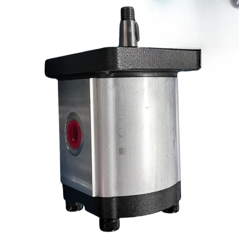


1. Ensure standard installation:
The equipment must be installed correctly and maintain good coaxiality with the drive motor to reduce vibration during operation, avoid abnormal wear of components, and lay a foundation for the stable operation of the equipment.
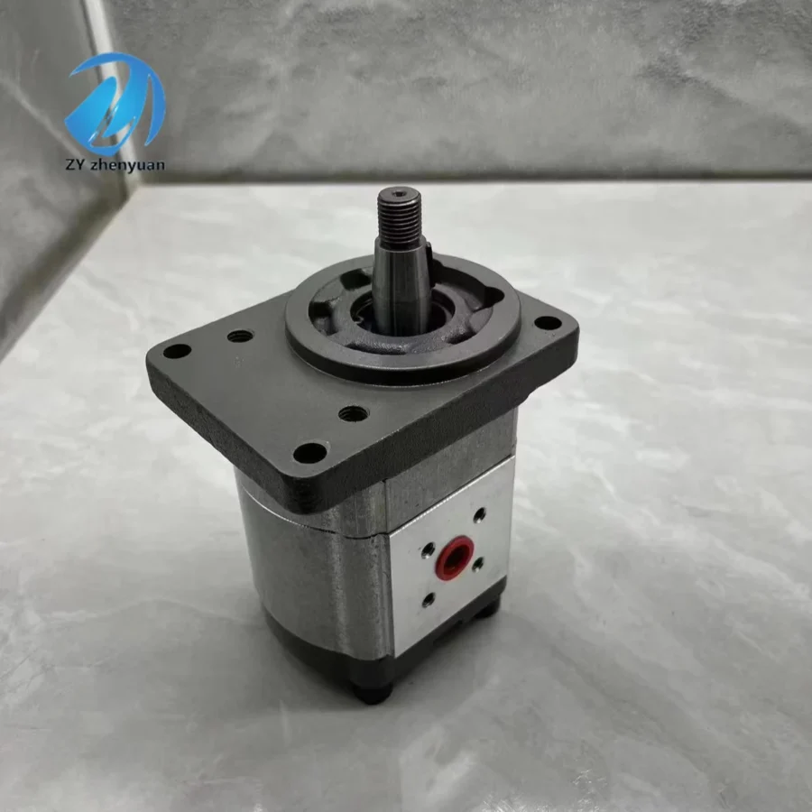
2. Check the oil before startup:
Before starting the gear pump, it is necessary to check the oil in the hydraulic system to ensure that the oil is sufficient and clean. Since gear pumps have specific requirements for the lubricating performance of oil, if the oil is seriously contaminated or has insufficient lubricity, it will accelerate the wear of core components such as gears and bearings, and shorten the service life of the equipment.
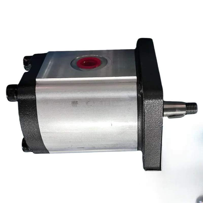
3. Control operating parameters:
During operation, the working pressure and speed must be strictly controlled within the range specified by the equipment, and long-term overload operation is strictly prohibited. Otherwise, it will cause the pump body to overheat, which will damage internal parts and affect the normal use of the equipment.
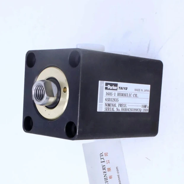
4. Regular inspection and maintenance:
During operation, it is necessary to regularly check whether the pump body has oil leakage, abnormal noise, severe vibration and other conditions. Once an abnormality is found, the machine should be shut down immediately for inspection, and the pump can be restarted only after troubleshooting and handling. At the same time, regularly replacing hydraulic oil and cleaning filters can effectively reduce impurities entering the pump body