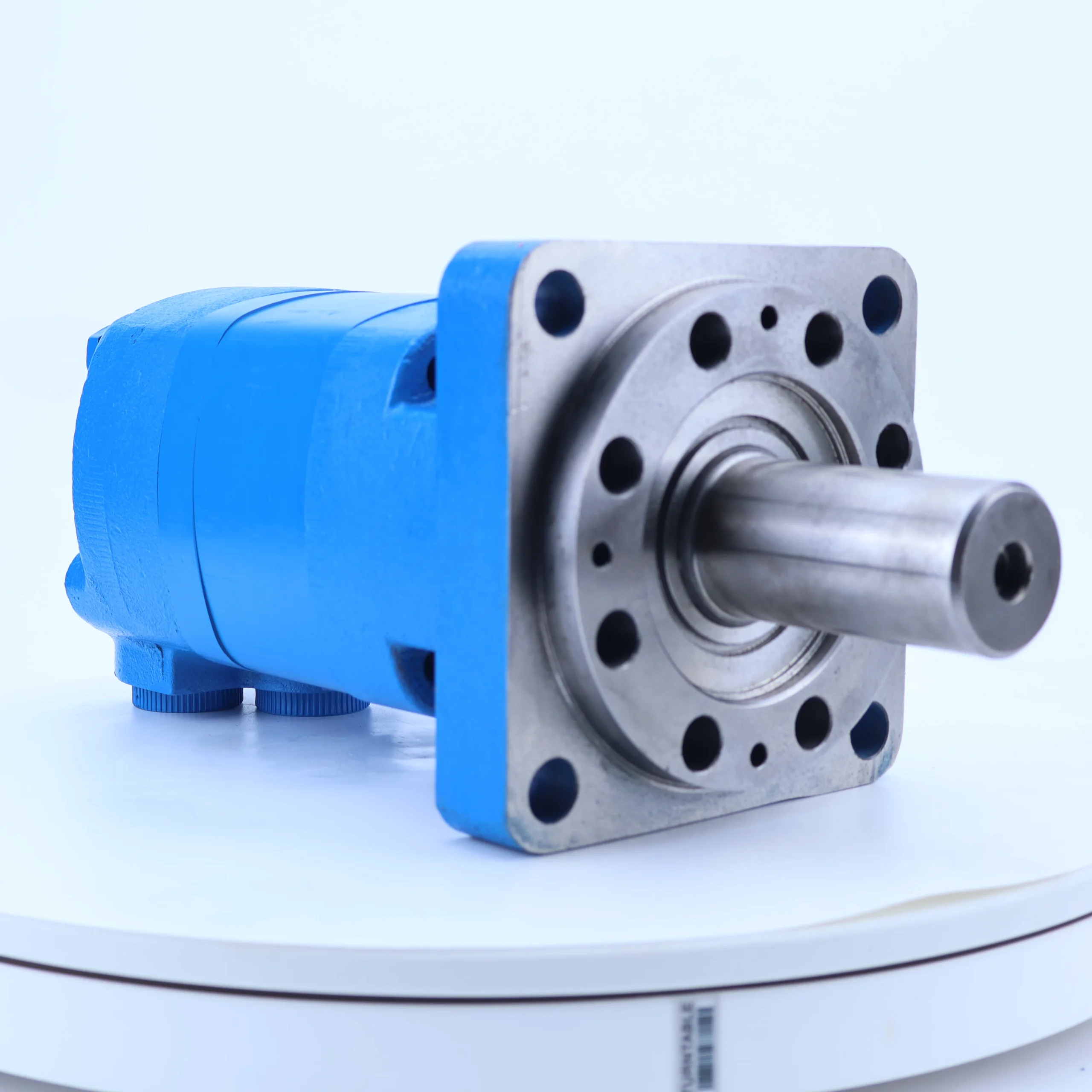
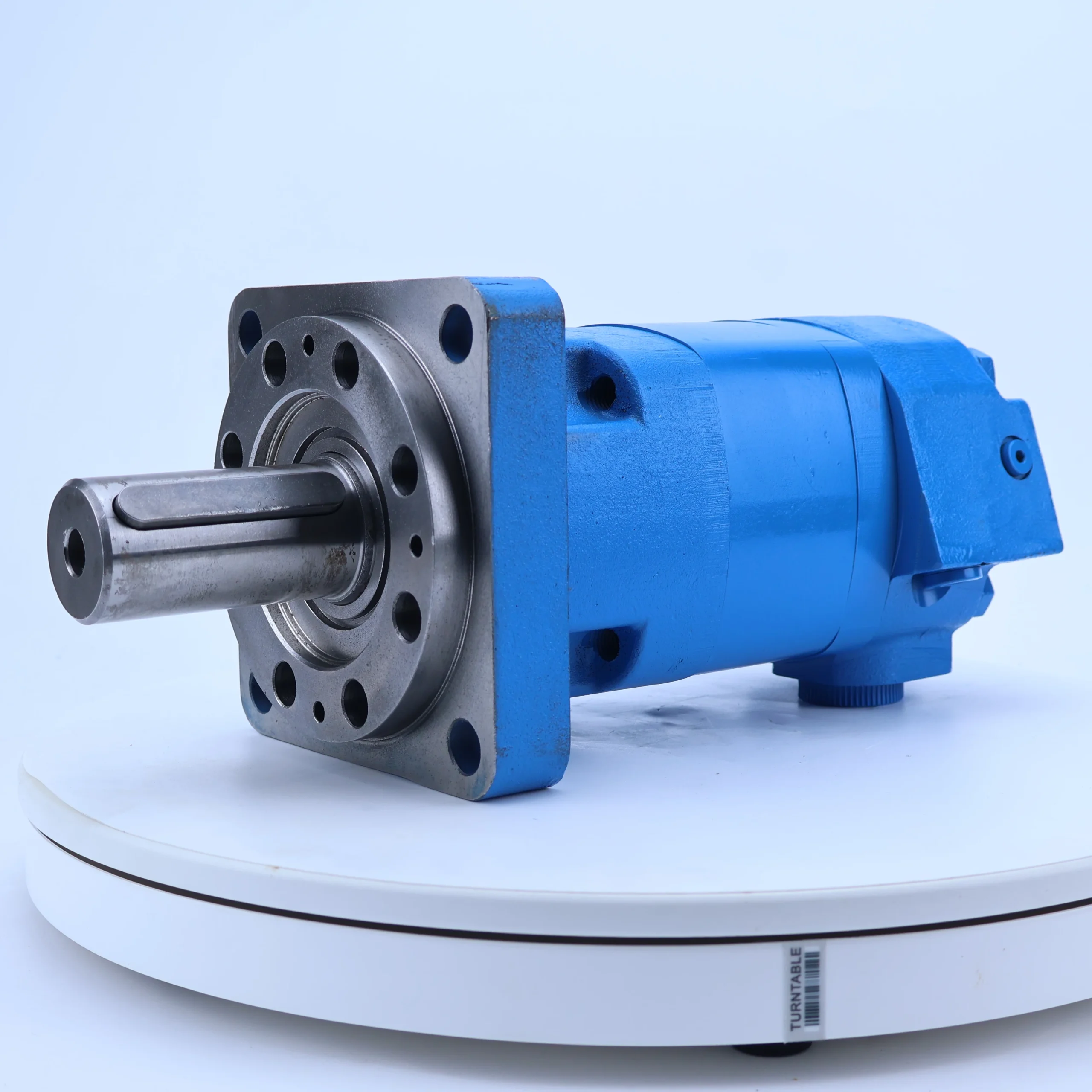
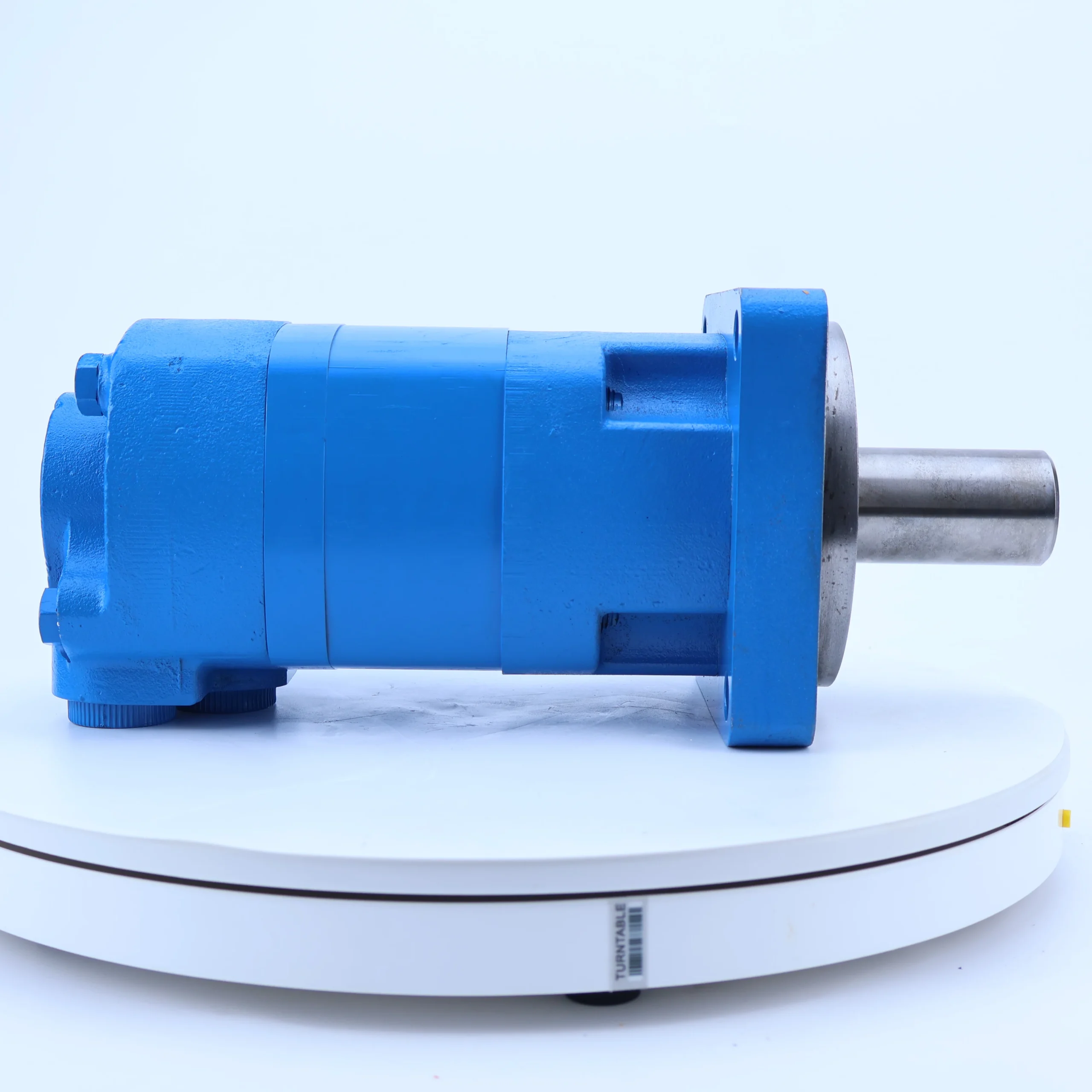


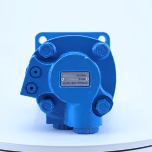
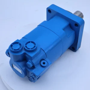
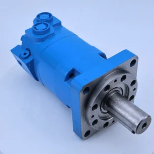
Hydraulic Orbit Motor 104 105 109 110 111 112 113 114 119 2K 6K BMER BMK Series 109-1236-006 Low Speed High Torque Piston Motor
Core performance parameters
– Motor type: Internal meshing cycloidal hydraulic motor, single-stage stator and rotor meshing structure, featuring low-speed and high-torque output characteristics, suitable for power drive scenarios of hydraulic system actuators.
– Pressure rating: Rated working pressure 16 MPa, peak working pressure 20 MPa (sustained for ≤5 seconds); The back pressure of the return oil is ≤1.0 MPa, and the pressure loss is ≤0.5 MPa (at the rated flow rate).
– Displacement and rotational speed: Rated displacement 109 mL/r (corresponding to the “109” mark on the model); Rated speed: 50-300 r/min, maximum speed: ≤350 r/min; It has good low-speed stability, with the minimum stable speed ≤10 r/min (no crawling).
– Torque and Efficiency: Output torque at rated speed ≥270 N·m; Volumetric efficiency ≥85%, total efficiency ≥80%; The power under rated working conditions is ≤ 8.5kW, suitable for medium-power hydraulic systems.
2. Structure and connection parameters
– Structural type: Horizontal installation structure, adopting “stator – cycloidal rotor – output shaft” transmission mechanism, integrated mechanical stop device (maximum stop torque 300 N·m); It is equipped with a built-in bidirectional overload oil replenishment valve to prevent suction damage.
– Core material: The cycloidal rotor is made of alloy structural steel (20CrMnTi, carburized and quenched, hardness HRC58-62); The stator is made of ductile iron (QT700-2, aged treatment). The output shaft is quenched and tempered with 40Cr, and the sealing parts are made of fluororubber (with a temperature resistance of -20℃ to 120℃).
– Connection specifications: Oil port (A/B port) diameter Φ 25mm, metric thread M30×2; The output shaft is connected by a flat key (keyway specification 12×8), and the installation flange complies with the ISO 7005-2 standard, with a flange center distance of 80×80 mm.
3. Medium and Environmental requirements
– Medium requirements: It is recommended to use L-HM 46 or L-HM 68 anti-wear hydraulic oil. L-HV 68 hydraulic oil should be selected for low-temperature environments. The kinematic viscosity of the oil is 20-400 mm²/s, and the moisture content is ≤0.1%.
– Cleanliness standard: The oil cleanliness should reach ISO 4406 17/14 grade, and a 10 μm fine filter should be installed at the oil inlet.
– Environmental parameters: Operating temperature -20℃ to 80℃, relative humidity ≤95% (no condensation); The protection grade is IP54, suitable for outdoor dust and oil contamination working conditions of construction machinery and agricultural machinery.Ii. Working Principle
This motor is an internal meshing cycloidal hydraulic motor. Its core operates through a mechanism of “pressure oil-driven stator and rotor meshing transmission + mechanical energy output”. The specific process is as follows:
The core process of power transmission
The high-pressure oil output by the hydraulic system enters the motor cavity through the oil inlet (A/B port). The pressure oil acts on the tooth profile surface of the cycloidal rotor, driving the rotor to perform planetary motion around the center of the stator – the rotor not only rotates on its own axis but also orbits around the center of the stator. The planetary motion of the rotor transmits its self-rotation motion to the output shaft through the cross coupling (or eccentric shaft), achieving continuous rotation of the output shaft and converting hydraulic energy into mechanical energy to do work externally. The low-pressure oil that has completed work is discharged through the return oil port, forming a circulation. The forward and reverse rotation of the output shaft can be achieved by switching the oil supply direction of the oil inlet (A/B port).
2. Key protection mechanisms
The motor is equipped with a built-in bidirectional overload oil replenishment valve. When the rotor rotates at high speed or the load suddenly changes, causing a sudden drop in local cavity pressure, the oil replenishment valve automatically opens, drawing oil from the oil tank to replenish the cavity and prevent cavitation damage. The integrated mechanical stop device is linked with the output shaft through friction plates, providing a stable stop torque when the motor is shut down to prevent the actuator from sliding down due to its own weight (such as crane booms and excavator buckets).
Iii. Product Features and Advantages
– Low speed and high torque, with excellent power characteristics: The output torque is ≥270 N·m at the rated speed of 50-300 r/min. It can directly drive heavy-duty actuators without a reduction mechanism, and the torque is 40% higher than that of gear motors of the same power. The minimum stable speed is ≤10 r/min, with no crawling phenomenon, making it suitable for precise speed regulation scenarios (such as paver material distribution).
– Compact structure, shock-resistant and highly reliable: The internal meshing cycloidal structure has fewer components and its volume is 30% smaller than that of a piston motor with the same torque. The rotor undergoes carburizing and quenching treatment, resulting in excellent wear resistance on the tooth surface. Under rated working conditions, the fault-free operation life can reach 10,000 hours. It can withstand a short-term overload torque of 10% and is suitable for the impact load conditions of construction machinery.
– Convenient forward and reverse rotation with good maneuverability: Forward and reverse rotation can be achieved by switching the fuel supply direction, and the response time for reversing is ≤0.5 seconds. The output shaft speed is linearly matched with the fuel supply flow rate, with a speed regulation accuracy of ±3%, making it suitable for scenarios that require frequent reversing (such as the bucket flipping of a loader).
– Integrated protection design, strong safety: Built-in overload oil replenishment valve and mechanical stop device, eliminating the cost of installing additional protection components; The oil replenishment valve prevents cavitation, the stop device avoids sliding down during shutdown, and the dual protection enhances the safety of the system.
– Easy maintenance and controllable cost: Modular structure design, with only seals, thrust bearings, etc. as vulnerable parts; The replacement of vulnerable parts does not require disassembling the overall structure. The maintenance time is no more than 1.5 hours, and the maintenance cost is 35% lower than that of plunger motors.
Iv. Usage Functions and Purposes
1. Core usage functions
– Low-speed heavy-load drive: It provides a stable torque of ≥270 N·m for the actuator, driving low-speed rotational actions (such as drum rotation, gear transmission), and is suitable for scenarios where high speed is not required but large torque is needed.
– Bidirectional rotation control: By switching the oil supply direction through the hydraulic valve group, the output shaft can rotate in both forward and reverse directions, meeting the reversing requirements of the actuator (such as bucket flipping and clamping mechanism opening and closing).
– Stable stop positioning: The mechanical stop device provides a stop torque of 300 N·m. When the machine stops, it fixes the position of the actuator to prevent unexpected actions caused by the self-weight of the load and enhance operational safety.
– Precise speed regulation operation: The rotational speed is linearly related to the fuel supply flow rate. By adjusting the flow valve, stepless speed regulation within the range of 50-300 r/min can be achieved, meeting the speed requirements under different working conditions.
2. Main application fields
– Construction machinery: Bucket rotating mechanism of small excavators, bucket flipping system of loaders, vibrating wheel drive of rollers, luffing mechanism of cranes.
– Agricultural machinery: Combine harvester header drive, corn harvester ear picking roller transmission, large tractor suspension mechanism rotation device.
– Industrial equipment: Drive for conveyor rollers, rotating mechanism of mixing tanks, traction system of small winches, drive for strapping mechanism of baling machines.
– Special equipment: Hoisting mechanisms for small port lifting equipment, auxiliary rotating devices for mine tunnel boring machines, and roller drives for sanitation equipment cleaning.
V. Applicable Machines and Scenarios
1. Adapt to the core machine
– Construction machinery: 6-10 ton small excavators, 1-3 ton loaders, small vibratory rollers, cranes under 5 tons.
– Agricultural machinery: Self-propelled combine harvesters, medium-sized corn harvesters, tractors with over 100 horsepower.
– Industrial equipment: small belt conveyors, vertical mixing tanks, small hydraulic winches, fully automatic baling machines.
– Special equipment: Small port cranes, micro mine boring machines, road sweepers.
2. Typical application scenarios
– Excavator bucket operation: As the power source for bucket rotation, it outputs a torque of 270 N·m to drive the bucket to rotate 360°, with a stable speed of 50-100 r/min. It is suitable for Angle adjustment during excavation and unloading, and there is no jamming when the load suddenly changes.
– Combine harvester header drive: Drive the header drum to rotate at a speed of 150-200 r/min. The stable torque ensures uniform cutting of crops by the header, meeting the harvesting requirements of different crops such as wheat and rice, with high reliability for continuous operation.
– Conveyor roller drive: It provides power for industrial conveyor rollers with a rotational speed of 200-300 r/min. By adjusting the flow rate, it can adapt to different conveying speeds to meet the assembly line conveying requirements of components and packages. The operating noise is ≤75 dB.
Six. Similar models
1. Alternative models of the same series
-109-1236-005: Small torque model of the same structure, rated displacement 109 mL/r, output torque ≥220 N·m, rated pressure 16 MPa, fully compatible installation dimensions, suitable for medium and light load scenarios (such as small conveyor rollers), with a 12% lower cost.
-109-1236-007: High-torque model of the same series, rated displacement 109 mL/r, output torque ≥320 N·m, peak pressure 22 MPa, material upgraded, suitable for heavy-duty scenarios (such as medium-sized excavator buckets), cost 18% higher.
2. Cross-series alternative models
-80-1236-006: Small displacement alternative model, rated displacement 80 mL/r, output torque ≥200 N·m, rated pressure 16 MPa, 20% smaller in size, suitable for light-load scenarios with limited installation space (such as small strapping machines), and 25% lower in cost.
-125-1236-006: Large-displacement alternative model, rated displacement 125 mL/r, output torque ≥300 N·m, rated pressure 16 MPa, speed range 40-280 r/min, suitable for high-torque scenarios (such as large mixing tanks), with a 20% higher cost.
-109-1237-006: High-pressure upgraded model, rated pressure 20 MPa, output torque ≥270 N·m, upgraded sealing parts and housing materials, suitable for medium-pressure systems (such as medium-sized cranes), cost 30% higher.
Vii. Precautions for Use
1. Oil management
– Select L-HM 46 or L-HM 68 anti-wear hydraulic oil. In low-temperature environments (below -20℃), replace it with L-HV 68 hydraulic oil. Oils of different grades must not be mixed. The oil of the new motor should be changed after the first 600 hours of operation, and then every 2,000 hours thereafter.
When the pressure difference of the 10 μm fine filter at the oil inlet exceeds 0.3 MPa, replace the filter element immediately. The moisture content (≤0.1%) and viscosity (20-400 mm²/s) of the oil should be tested monthly. When emulsification or impurities are present, the system needs to be cleaned and the oil changed.
2. Installation and commissioning
When installing, the coaxiality error between the output shaft and the load shaft should be no more than 0.15mm. The flange bolts should be evenly tightened (with a torque of 150 N·m) to avoid eccentricity causing bearing wear. The oil port connection must be reliably sealed to prevent high-pressure oil leakage.
Before the first start-up, fill the motor with hydraulic oil and manually rotate the output shaft 2-3 times to ensure there is no jamming. After startup, run no-load for 10 minutes (at a speed of 100 r/min). Wait until the oil temperature rises above 30℃ before gradually loading. The load increase rate should be no more than 20% per minute.
3. Operation and Maintenance
During operation, monitor the temperature of the motor housing (normal ≤75℃, maximum ≤85℃), inlet and outlet pressures (≤16 MPa), and operating noise (≤78 dB). If a sudden temperature rise, abnormal pressure or unusual noise is detected, stop the machine immediately and check the cleanliness of the oil or the wear of the stator and rotor.
– Regular maintenance every 2,500 hours: Replace seals and thrust bearings; Check the wear of the rotor tooth surface (replacement is required if the wear is greater than 0.05mm). Disassemble and inspect the inner tooth surfaces of the stator every 5,000 hours. If necessary, grind and repair them.
4. Storage and Protection
When stored for A long time, seal the A/B ports with the oil port plug, inject anti-rust oil (80% volume) into the shell, and place it in a dry and well-ventilated area (temperature 5-35℃, humidity ≤60%). Manually rotate the output shaft once a month to prevent jamming and rusting.
Before putting it into use after being idle for more than 8 months, drain the anti-rust oil, rinse the shell twice with new oil, run it no-load for 15 minutes, and then gradually load it. Only after confirming that the forward and reverse rotations are normal and there is no leakage can it be put into use.


