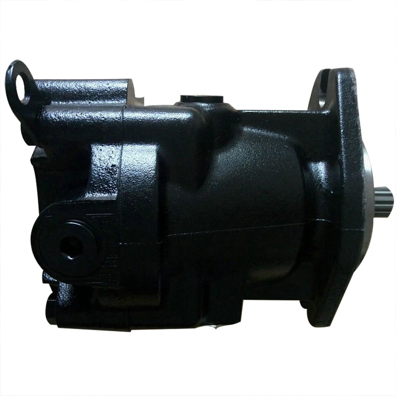
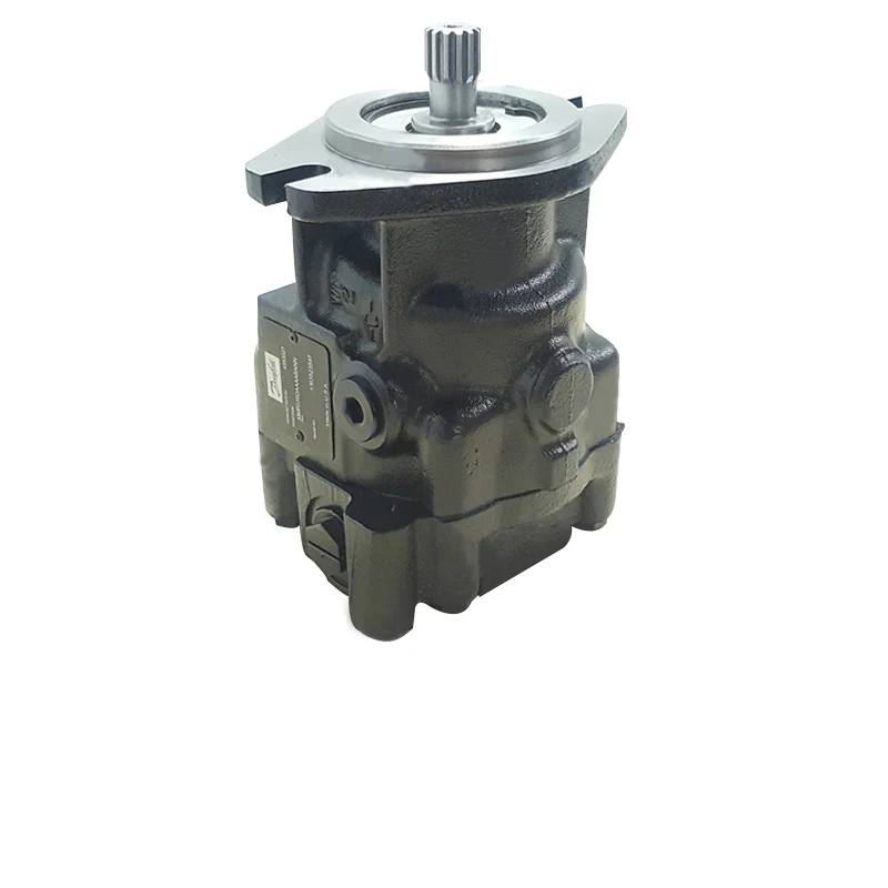
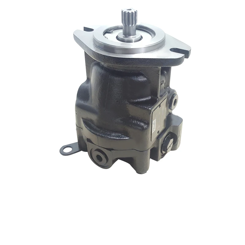

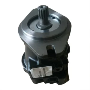
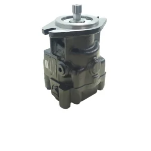
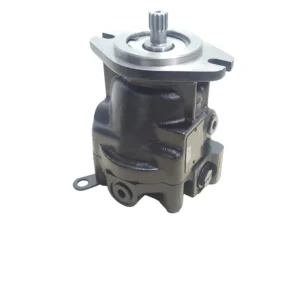
MMF044DAFHABNNN Hydraulic Piston Pump MMV MMF MMV044 MMF044 MMV044D MMF044D MMF046 Axial Variable Piston Motor
Displacement and flow rate
Theoretical displacement: 44 mL/r, suitable for medium and high-pressure systems with small and medium flow rates.
Rated flow rate: At the rated speed of 3000 rpm, the output flow rate is approximately 132 L/min. At the maximum rotational speed of 4500 rpm, the maximum flow rate can reach 198 L/min, meeting the flow fluctuation requirements of dynamic loads.
2. Work pressure
Continuous working pressure: 31.5 MPa (315 bar), capable of stably bearing medium and heavy loads for a long time.
Intermittent peak pressure: 35 MPa (350 bar), single duration ≤10 seconds, capable of handling sudden impact loads.
3. Speed range
Rated speed: 2000-3000 rpm, suitable for medium and high-speed output characteristics of engines or motors.
Maximum allowable speed: 4500 rpm, minimum stable speed ≥600 rpm, to avoid insufficient lubrication of the plunger or cavitation at low speeds.
4. Control mode
The variable pump design supports load sensitivity (LS) and electro-hydraulic proportional combined control. The input signal is 4-20mA or 0-10V, with a response time of ≤0.3 seconds. The displacement can be dynamically adjusted (5%-100%) to match the load requirements.
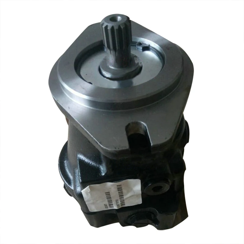
5. Structural form
The swash plate axial plunger structure, open circuit design, high-strength cast iron pump body, and key friction pairs (plunger and cylinder bore, distribution plate) are processed by nitriding and precision grinding, with a surface hardness of HRC60-62 and excellent wear resistance.
◦ Shaft end seal: Double-lip fluororubber oil seal + dust-proof lip, protection grade IP65, suitable for dusty and humid environments.
6. Oil requirements
◦ Applicable viscosity: 15-200 mm²/s. ISO VG 46 anti-wear hydraulic oil is recommended.
Working oil temperature: -20℃ to 80℃. The oil cleanliness should reach ISO 16/13 grade (NAS 8 grade), and a 3-5 μm fine filter should be configured.
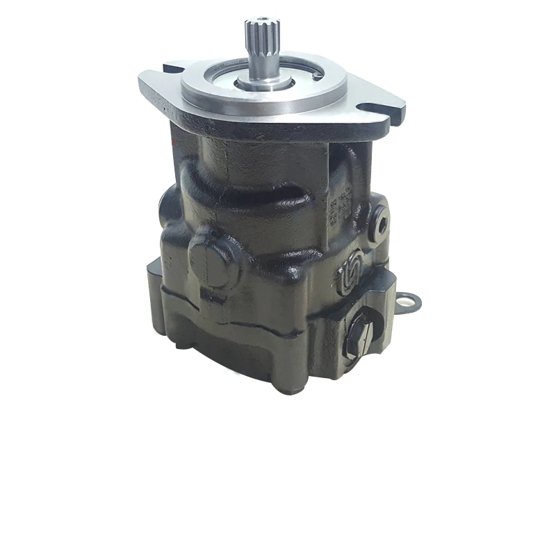
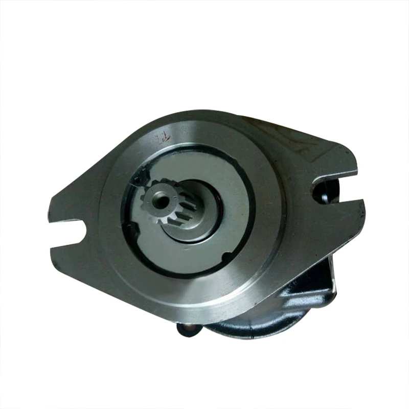
7. Installation and adaptation
◦ Shaft end: Flat key connection, shaft diameter φ 45mm, in compliance with ISO 3019-2 standard.
◦ Flange installation: SAE B 4 bolt flange, oil port specifications: Inlet G1, outlet G3/4, supports horizontal or vertical installation, total weight approximately 32 kg.
8. Other parameters
The volumetric efficiency is ≥93% (under rated conditions), the total efficiency is ≥89%, and the no-load noise is ≤76 dB (at 3000 rpm).Ii. Working Principle
This pump is a swashplate axial piston variable pump. Its core consists of a drive shaft, cylinder block, piston assembly, swashplate and control valve body. It achieves oil suction, oil pressure and dynamic flow regulation through the reciprocating motion of the piston. The specific process is as follows:
1. Oil absorption process: The prime mover drives the drive shaft to rotate the cylinder block. Under the action of the return spring and centrifugal force, the plunger tightly adheres to the swash plate. When the plunger rotates with the cylinder block to the lower side area of the swash plate, it extends outward, increasing the volume of the cylinder block’s sealed cavity to form a vacuum. The hydraulic oil then enters the cavity through the oil inlet and the oil suction groove of the distribution plate.
2. Oil pressure process: When the plunger rotates to the high side area of the swash plate, the inclined surface of the swash plate compresses the plunger to contract inward, reducing the volume of the cavity and increasing the oil pressure. The oil is then discharged to the system through the oil distribution plate’s oil channel and the oil outlet, completing the conversion from mechanical energy to hydraulic energy.
3. Variable regulation: The load-sensitive valve group detects the system’s pressure and flow requirements in real time and adjusts the swash plate Angle through electro-hydraulic proportional signals – when the load increases, the swash plate Angle increases, the plunger stroke lengthens, and the displacement increases. When the load is reduced, the inclination Angle decreases and the displacement drops, achieving “on-demand fuel supply” and reducing energy waste.
Iii. Product Features and Advantages
1. High-pressure adaptability and flow flexibility: The continuous pressure of 31.5 MPa is suitable for heavy loads of 20-25 ton equipment, and the flow range of 132-198 L/min can meet the collaborative operation requirements of multiple actuating elements (such as excavation, rotation, and lifting).
2. High efficiency and energy-saving performance:
The volumetric efficiency is ≥93%, the total efficiency is ≥89%, and it saves more than 18% energy compared with traditional quantitative pumps.
Load sensitive control reduces throttling losses during “high flow and low load”, lowers system temperature rise by 15℃, and extends the hydraulic oil replacement cycle to over 3,000 hours.
3. Anti-pollution and reliability:
The plunger and cylinder hole clearance seal is optimized, combined with an anti-wear coating, ensuring a service life of over 6,000 hours in ISO 18/15 grade contaminated environments (such as mine dust).
Integrated oil temperature and oil pressure monitoring interfaces support early warning of faults, reducing the risk of sudden shutdowns.
4. Rapid control response: Electro-hydraulic proportional regulation can quickly adapt to load fluctuations. The response time from 5% to 100% displacement is ≤0.3 seconds, ensuring the coordination and accuracy of equipment operations.
5. Easy maintenance: The modular pump core design allows for the individual replacement of vulnerable parts such as the plunger assembly and distribution plate without the need for overall disassembly. Standardization of sealing parts reduces maintenance costs by 30%.
Iv. Usage Functions and Purposes
1. Usage function:
As the power source of the hydraulic system, it drives the hydraulic cylinder and hydraulic motor to achieve a power output with a linear push-pull force of ≥350 kN or a rotational torque of ≥1500 N · m.
Through load sensitivity and proportional control, the flow of multiple actuating elements is dynamically allocated (such as when an excavator simultaneously completes excavation and rotation) to avoid motion interference.
The built-in pressure compensation valve automatically limits the displacement when the system pressure reaches the peak of 35 MPa, and in combination with the relief valve, it achieves dual overload protection.
2. Usage
◦ Construction machinery: The main hydraulic system of 20-25-ton crawler excavators, the lifting and flipping mechanism of medium-sized wheel loaders, and the luffing drive of crawler cranes;
◦ Industrial equipment: Clamping and injection drive systems for 800-1200 ton injection molding machines, roller hydraulic systems for metallurgical production lines;
◦ Mining machinery: Cutting head drive and hydraulic support pushing device for small and medium-sized mine roadheaders.
V. Applicable Machines and Scenarios
1. Applicable machines
20-25 ton crawler excavators, 50 ton wheel loaders, 150 ton crawler cranes;
800-1200 ton injection molding machines and mining tunnel boring machines with diameters of 3-4 meters.
2. Applicable scenarios:
◦ Medium and high-pressure compound action scenarios: earthwork operations by excavators (simultaneous excavation, rotation, and unloading), and the coordination of luffing and rotation during crane hoisting.
Scenarios with significant load fluctuations: foundation pit excavation in construction projects, intermittent stamping operations in factory workshops;
Moderately polluted environments: Urban infrastructure construction sites, small and medium-sized mines, port bulk cargo handling and other scenarios where oil is prone to mixing with a small amount of impurities.
Six. Similar models
1. Same series models:
◦ MMF032DAFHABNNN: Displacement 32 mL/r, rated flow 96 L/min (3000 rpm), suitable for 15-20 ton class equipment, and the flow rate is more in line with the requirements of medium and small loads;
◦ MMF056DAFHABNNN: Displacement 56 mL/r, rated flow 168 L/min (3000 rpm), high-flow model, suitable for heavy equipment of 25-30 tons.
2. Similar alternative models:
Swashplate axial piston pump (such as A series 40 bore) : Rated pressure 31.5 MPa, displacement 45 mL/r, supports load sensitive control, and has the same structural principle;
Variable piston pumps (such as model B Series 045) : Displacement 45 mL/r, pressure 35 MPa, more compact in size, suitable for equipment with limited installation space.
Vii. Precautions for Use
1. Oil management:
Strictly use the specified grade of anti-wear hydraulic oil. Do not mix oils of different brands or grades to avoid aging of seals due to additive reactions.
Install a ≥100 μm screen filter at the oil suction port, and add a 3 μm fine filter to the return oil line. Check the filter element every 500 hours, replace the hydraulic oil and clean the oil tank every 2500 hours.
2. Installation requirements:
The prime mover is connected by an elastic coupling, with the coaxiality error of the two shafts being no more than 0.1mm and the angular error no more than 0.5°, to prevent excessive radial force from damaging the bearings.
The length of the suction pipeline should be no more than 1.8m, and its diameter should not be less than the specification of the pump’s oil inlet. The number of elbows should be reduced (no more than 2). The installation height should be more than 400mm lower than the liquid level of the oil tank to prevent cavitation.
3. Startup and Operation Monitoring:
Before the first start, fill with clean oil and manually turn the wheel 3 to 5 times to ensure there is no jamming. After starting, run it at low speed (800 rpm) without load for 10 minutes. When the oil temperature rises above 30℃, gradually load it.
During operation, monitor the oil temperature (35-75℃ is the best), pressure (long-term overpressure is strictly prohibited) and vibration (≤ 4mm /s). If any abnormality is detected, stop the machine immediately for inspection.
4. Maintenance and Care
Check the shaft seal every 1000 hours. Replace the seal when the leakage is greater than 3 drops per minute. Disassemble and inspect the friction pair every 3,000 hours. If the wear exceeds 0.04mm, maintenance is required.
Calibrate the control module every 5,000 hours to ensure that the displacement matches the signal linearly and avoid system shock.
5. Security and Storage
Before maintenance, cut off the power source and release the pressure. Disassemble only when the oil temperature drops below 40℃.
When the machine is out of service for a long time (more than 3 months), drain the oil, add anti-rust oil, seal the oil port, and store it in a dry and well-ventilated place (humidity ≤65%).


