


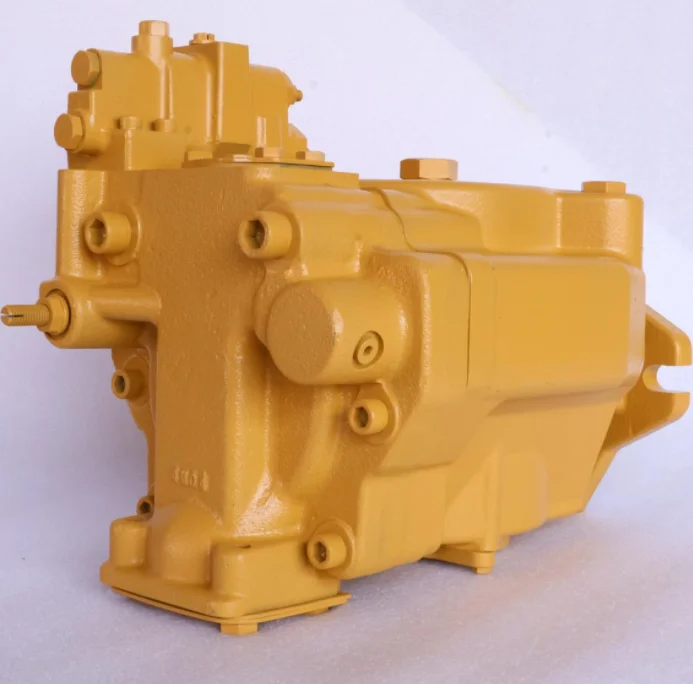
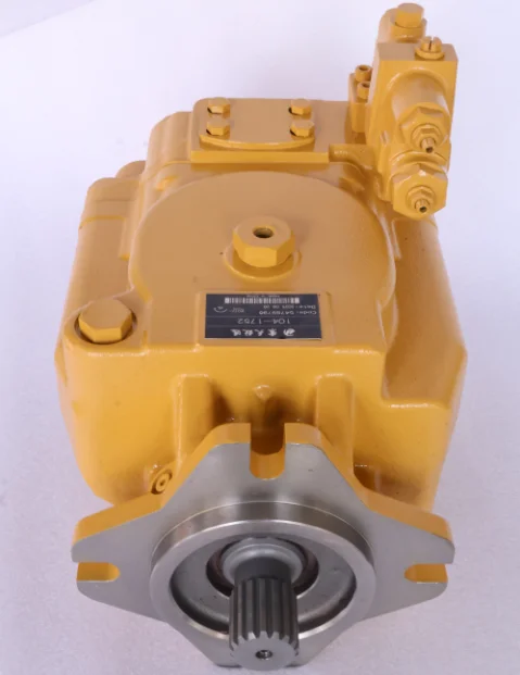
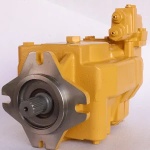
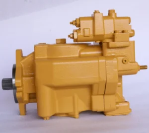
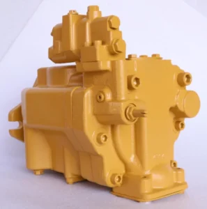
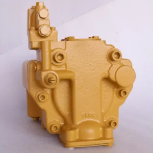


OEM Excavator Hydraulic Main Pump 104-1752 9T-8346 0R-7669 for D9R High Pressure Piston Pump CA1041752 1041752
Core parameters of displacement and pressure
Theoretical displacement: 74 mL/r (ml/RPM), medium displacement specification, suitable for medium and small-sized to medium-high pressure hydraulic systems.
◦ Pressure rating: Continuous rated pressure 28 MPa (280 bar), capable of withstanding medium and high-pressure cyclic operations for a long time; The instantaneous peak pressure is 32 MPa (320 bar), with a single duration of no more than 10 seconds. It is suitable for start-up shock, sudden load changes and short-term heavy load conditions.
◦ Adjustment range: Displacement adjustment ratio 0-100% (swash plate variable mechanism supports stepless adjustment), pressure control accuracy ±1.5%, suitable for wide-range variable flow demand scenarios.
2. Rotational speed and flow performance
Rated speed: 1500-1800 rpm, suitable for the commonly used output speeds of medium-sized engines and industrial three-phase asynchronous motors.
◦ Flow output: At a rated speed of 1800 rpm and 100% displacement, the maximum flow rate can reach 133.2 L/min. At 1000 rpm, the flow rate is 82.2 L/min, meeting the requirements for the coordinated operation of 2 to 4 medium and high-pressure actuators. The flow stability error at a low speed of 500 rpm is ≤3%.
◦ Steering requirements: Unidirectional counterclockwise rotation (shaft end view), with involute spline transmission at the shaft end (specification: 12×3× 40mm).
3. Structure and material specifications
Structural type: Single-stage axial piston variable pump, adopting the design of “9 pistons symmetrically arranged + swashplate variable mechanism”, piston stroke 13mm, cylinder body and output shaft synchronous speed, swashplate Angle adjustment range 0-18°.
Core material: The plunger is made of 42CrNiMoA alloy structural steel (nitrided, surface hardness HV950-1050); The cylinder block is made of QT800-2 ductile iron. The oil distribution plate is made of ZCuAl10Fe3 copper-based alloy with ceramic coating. The seal is a combination seal of polytetrafluoroethylene and fluororubber (with a temperature resistance range of -30 ℃ to 120℃).
◦ Efficiency indicators: Volumetric efficiency ≥95% under rated working conditions, total efficiency ≥91%; The volumetric efficiency still remains at ≥93% when the displacement is 50%.
4. Installation and adaptation parameters
◦ Installation specification: SAE type C flange installation, positioning pin diameter Φ12mm, installation center distance 75mm; The shaft end has an extension length of 45mm and supports connection with elastic couplings or membrane couplings.
◦ Oil port specifications: The suction port is G2, the pressure port is G1 1/2, and the control port is G1/4. All are connected by internal threads and are suitable for medium and high-pressure high-flow hydraulic pipelines.
Weight and dimensions: The overall weight of the machine is 50 kg, with a length × width × height of 320×220×180 mm. The compact structure is suitable for the installation space of medium-sized equipment.
5. Oil and environmental requirements
Oil specification: It is recommended to use L-HM 46 anti-wear hydraulic oil. For cold regions below -30℃, L-HV 46 low-temperature anti-wear hydraulic oil should be selected. The viscosity range of the oil is 18-450 mm²/sYUKEN.
◦ Working environment: The oil cleanliness should reach ISO 15/12 grade (NAS 6 grade), the working oil temperature should be between -25 ℃ and 90℃, and the relative humidity should be ≤95% (without condensation). It can adapt to harsh working conditions such as strong vibration and high dust.Ii. Working Principle
This pump is a single-stage axial piston variable pump. Its core achieves medium and high pressure large flow output and precise displacement control through a closed-loop mechanism of “power transmission – piston reciprocating motion – swash plate Angle adjustment”. The specific working process is as follows:
1. Power transmission and plunger drive: The power source drives the output shaft to rotate through splines. The shaft end drives the cylinder block to rotate synchronously through the thrust bearing. Under the combined action of centrifugal force, the elastic force of the return disc and high-pressure oil, the ball heads of the 9 plungers inside the cylinder block always closely adhere to the working surface of the swash plate. The swash plate is driven by a servo variable mechanism and can flexibly adjust the inclination Angle. When the plunger rotates with the cylinder block, it moves back and forth along the cylinder block holes in a straight line, forming a compound action of “rotation + reciprocation”, providing stable power for the suction oil circulation.
2. Core process of suction and pressure oil circulation
◦ Oil suction stage: When the plunger rotates with the cylinder to the transition area from the lower to the higher position of the swash plate, the plunger gradually extends out of the cylinder, increasing the volume of the sealed cavity and creating a local vacuum. Under the action of atmospheric pressure, the oil in the oil tank is sucked into the cavity through the oil suction port and the oil suction window of the oil distribution plate.
◦ Oil pressure stage: When the plunger rotates to the transition area from the high to the low position of the swash plate, it is squeezed back into the cylinder by the swash plate, and the cavity volume is rapidly compressed. The oil is pressurized to the rated pressure and then output to the hydraulic system through the oil pressure window and the oil pressure port of the oil distribution plate. Each time the cylinder block rotates once, each plunger completes one suction oil cycle. The nine plungers work alternately to achieve continuous and stable oil supply.
3. The stepless variable regulation mechanism system inputs a control pressure of 0.8-2.2 MPa to the servo variable mechanism according to the load demand, driving the servo valve to deflect the swash plate. When the swash plate inclination Angle increases from 0° to 18°, the plunger stroke increases from 0 to 13 mm, and the pump output displacement linearly rises from 0 to 100% (133.2 L/min). When the inclination Angle decreases, the displacement drops simultaneously, achieving stepless flow regulation. The precise fit between the ceramic coating of the oil distribution plate and the cylinder body (with a gap of ≤ 0.004mm) ensures strict isolation of the suction oil chamber. Combined with the pressure feedback device, the flow regulation response time is ≤0.12 seconds.
4. Pressure Stability and Wear control: The symmetrical arrangement design of the 9 plungers ensures complete radial force balance on the cylinder block, avoiding additional wear on the bearings caused by radial force. High-pressure oil penetrates through the gap between the plunger and the cylinder block to form a dynamic lubricating oil film. Combined with the self-lubricating coating of the oil distribution plate, it achieves dual guarantees of sealing and lubrication. Under rated working conditions, the oil temperature remains stable within 90℃, and the trouble-free operation life is significantly extended.
Iii. Product Features and Advantages
1. Strong adaptability to medium displacement and high pressure: With a medium displacement of 74 mL/r and a rated pressure of 28 MPa, it outputs a large flow rate of 133.2 L/min at 1800 rpm. It can be adapted to medium-sized hydraulic systems and drive 2 to 4 actuating elements to complete compound actions such as excavation, lifting, and pressing. Compared with gear pumps of the same displacement, the pressure adaptation range is expanded by 35%, making it suitable for more complex working conditions.
2. The stepless variable energy-saving efficiency is high. The displacement can be adjusted steplessly from 0 to 100%, and the flow rate can be matched in real time according to the load, avoiding the throttling energy loss of traditional fixed displacement pumps. It saves more than 28% energy compared with the fixed displacement pump system. Under the 50% displacement condition, the efficiency still remains at ≥93%, suitable for intermittent variable load scenarios such as injection molding machine pressure holding and press pressing, with an annual energy-saving cost exceeding 60,000 yuan.
3. The high-stability and long-life design features a plunger nitrided treatment and a ceramic coating on the oil distribution plate to form a high-strength wear-resistant pair. Under a rated pressure of 28 MPa, the trouble-free working life exceeds 15,000 hours. The QT800-2 cylinder block has an impact resistance strength of 140 J/cm², capable of withstanding frequent starts and stops as well as load impacts. Its service life is 25% longer than that of pump bodies made of ordinary materials.
4. Excellent wide operating condition adaptability: It can operate within a wide temperature range from -25℃ to 90℃. There is no jamming when starting at low temperatures in cold regions, and it has strong thermal stability in high-temperature environments. It meets the ISO 15/12 grade oil cleanliness compatibility requirements and can adapt to harsh working conditions such as mines and construction sites. The interval between failures is 40% higher than that of ordinary pumps. YUKEN Oil Research.
5. Standardized integrated maintenance is convenient. The SAE C type standardized flange and oil port design improves installation compatibility by 70% compared to customized pumps and can directly replace products of the same specification but different series. The modular servo variable mechanism design allows for the separate disassembly and replacement of vulnerable parts. The fault detection time is no more than 20 minutes, and the annual maintenance cost is 30% lower than that of imported pumps of the same level.
Iv. Usage Functions and Purposes
1. Core usage functions
◦ Medium and high pressure large flow output: Rated pressure of 28 MPa + maximum flow rate of 133.2 L/min, providing stable power for medium and high pressure systems, driving actuators to perform medium and high-intensity actions such as excavation, lifting, clamping, and pressing, supporting complex compound collaborative operations of 2 to 4 actuators.
◦ Precise stepless variable regulation: The flow rate is adjusted from 0 to 133.2 L/min through servo control of the oil port pressure, with a response time of ≤0.12 seconds and a flow rate regulation accuracy of ≤2.5%. It is suitable for dynamic requirements of multiple working conditions such as pressure holding (low flow high pressure), rapid advancement (large flow low pressure), and uniform operation (constant flow).
Overload protection and anti-pollution: Overload protection is achieved in conjunction with the system relief valve (recommended setting pressure of 30 MPa), and the built-in pressure compensation device can automatically limit the maximum pressure. The ceramic coating of the oil distribution plate enhances the anti-pollution ability and is compatible with NAS level 6 oil cleanliness, reducing the risk of failure under harsh working conditions.
2. Main application fields
◦ Construction machinery: Main hydraulic systems for 15-25-ton excavators, lifting and flipping systems for 8-12-ton loaders, lifting mechanisms for 10-15-ton forklifts, power systems for hydraulic breakers, and drilling systems for small rotary drilling RIGS.
Industrial manufacturing equipment: 500-800 ton hydraulic presses, medium-sized injection molding machine clamping and injection systems, multi-station hydraulic fixtures for automated production lines, main drive systems for metal forming machines, injection systems for large die-casting machines.
Specialized and heavy machinery: medium-sized ship hydraulic steering gear + anchor winch system, small tunnel boring machine hydraulic system for mining, large agricultural machinery (combine harvester) execution system, hydraulic positioning system for medical imaging equipment.
V. Applicable Machines and Scenarios
1. Adapt to the core machine
Construction machinery: 15-25 ton excavators, 8-12 ton loaders, 10-15 ton forklifts, hydraulic breakers, small rotary drilling RIGS.
Industrial equipment: 500-800 ton class presses, medium-sized injection molding machines, multi-station automated fixtures, metal forming machines, large die-casting machines.
Specialized machinery: medium-sized ships, small tunnel boring machines, large combine harvesters, medical image positioning equipment.
2. Typical application scenarios
In the compound action scenarios of medium-sized equipment: The 18-ton excavator performs three coordinated actions of digging, boom lifting, and boom extension and retraction, and the loader performs continuous operations of lifting and flipping. With a flow rate of 133.2L /min, it can simultaneously supply fuel to multiple actuators, and the operation efficiency is 40% higher than that of the single-pump system of the same level.
Variable load energy-saving scenarios: For medium-sized injection molding machines, the cycle operation of mold locking (high pressure and low flow) – injection (medium pressure and high flow) – pressure holding (low pressure and low flow) – mold opening (medium pressure and high flow) is carried out. The variable adjustment reduces the energy consumption per unit product by 32%, and the annual energy-saving cost exceeds 80,000 yuan.
Suitable scenarios for harsh working conditions: Hydraulic systems of tunnel boring machines in mining sites and execution systems of combine harvesters in farmlands. The wide temperature range and high anti-pollution design enable the equipment to extend the failure interval to over 1000 hours under low-temperature conditions of -20 ℃ and high dust concentration, which is 50% longer than that of ordinary pumps.
Six. Similar models
1. Alternative models of the same series
◦ 104-1750: It is of the same series as the target model, with the same structure and control mode. The theoretical displacement is reduced to 65 mL/r, the rated pressure is 28 MPa, and the maximum flow rate at 1800 rpm is 117 L/min. It is compatible with 12-20 ton excavators and 400-600 ton presses, and the installation dimensions are fully compatible.
◦ 104-1754: The displacement is increased to 85 mL/r, the rated pressure is 28 MPa, and the maximum flow rate at 1800 rpm is 153 L/min. It is suitable for 25-30 ton excavators and 800-1000 ton presses. The pressure characteristics are the same as those of model 74.
2. Cross-series alternative models
A10VSO140DR/31R-PPB12N00: Axial piston variable pump, displacement 140 mL/r, rated pressure 31.5 MPa, volumetric efficiency ≥95%, adopts constant power + constant pressure compound control, suitable for heavy-load scenarios of construction machinery.
PVH74-QIC-RAF-1S-10-C25-31: Axial piston variable pump, with a displacement of 74 mL/r and a rated pressure of 25 MPa. It adopts a pressure compensation variable mechanism, and its anti-pollution capacity is 15% higher than that of the 104 series. It is suitable for harsh working conditions such as mining and agriculture.
HPV63-21: Single-pump axial piston variable pump with a displacement of 74 mL/r and a rated pressure of 25 MPa. It adopts a simplified servo variable structure and has a cost 22% lower than the 104 series. It is suitable for industrial equipment that is sensitive to cost.
Vii. Precautions for Use
Core norms for oil and Fluid management
Strictly select L-HM 46 or L-HV 46 anti-wear hydraulic oil. Do not mix different brands, grades of oil or inferior oil to avoid abnormal wear of the plunger and the oil distribution plate and jamming of the servo variable mechanism. The first oil change cycle is 1000 hours, and then it should be changed every 2000 to 2500 hours. Before changing the oil, the pump chamber and pipelines should be flushed with new oil (the flushing oil volume should be ≥ 2.5 times the system volume). YUKEN Oil Research.
A 10μm high-precision filter must be installed at the oil inlet, a 5μm fine filter at the oil return port, and a 3μm ultra-fine filter at the control oil port separately. The contamination level of the filter should be checked every 600 hours. When the pressure difference exceeds 0.35 bar, the filter element should be replaced immediately. The fuel tank needs to be cleaned every 4,000 hours, with sediment thickness ≤0.5mm and oil moisture content ≤0.08%. YUKEN oil research.
2. Installation and commissioning requirements
The diaphragm coupling is adopted for connection. The coaxiality error of the two shafts is ≤ 0.08mm, and the angular error is ≤0.3°, which avoids radial force causing cylinder block eccentric wear and bearing wear (reducing service life by more than 60%). When installing the SAE C type flange, the pre-tightening torque of the bolts should be uniformly controlled at 120-150 N · m to prevent leakage of the end cover seal.
The diameter of the oil suction pipeline is ≥Φ40mm, the length is ≤2.0m, the number of elbows is ≤2, and the oil suction resistance is ≤ 0.012MPa (to prevent cavitation from scratching the plunger). The pressure oil pipeline needs to be equipped with a 0-30 MPa shock-resistant pressure gauge. The diameter of the control oil pipeline should be ≥Φ10mm, and the spacing of the pipeline support should be ≤0.8m to reduce the influence of vibration on the adjustment accuracy. YUKEN Oil Research.
3. Startup and operation monitoring
Before the initial start-up, clean hydraulic oil should be filled into the pump body and the servo variable mechanism. Manually turn the wheel 8 to 10 times to ensure smooth rotation. When starting at temperatures below -20℃, heat the oil to above -5 ℃. Run the YUKEN oil research machine at a low speed of 1000 rpm without load for 15 minutes. When the oil temperature rises above 35℃, gradually increase the load (pressure increase rate ≤2.5 MPa/minute). Do not run the machine at full load when it is cold.
◦ Core parameters for monitoring during operation: Oil temperature: 35-90℃ (if the temperature exceeds 95℃, the machine should be shut down to check the cooling system), system pressure: ≤28 MPa (peak value not exceeding 32 MPa and single time ≤10 seconds), shaft end leakage: ≤3 drops per minute, variable adjustment response time: ≤0.12 seconds, operating noise: ≤78 dB (under 1500 rpm conditions).


