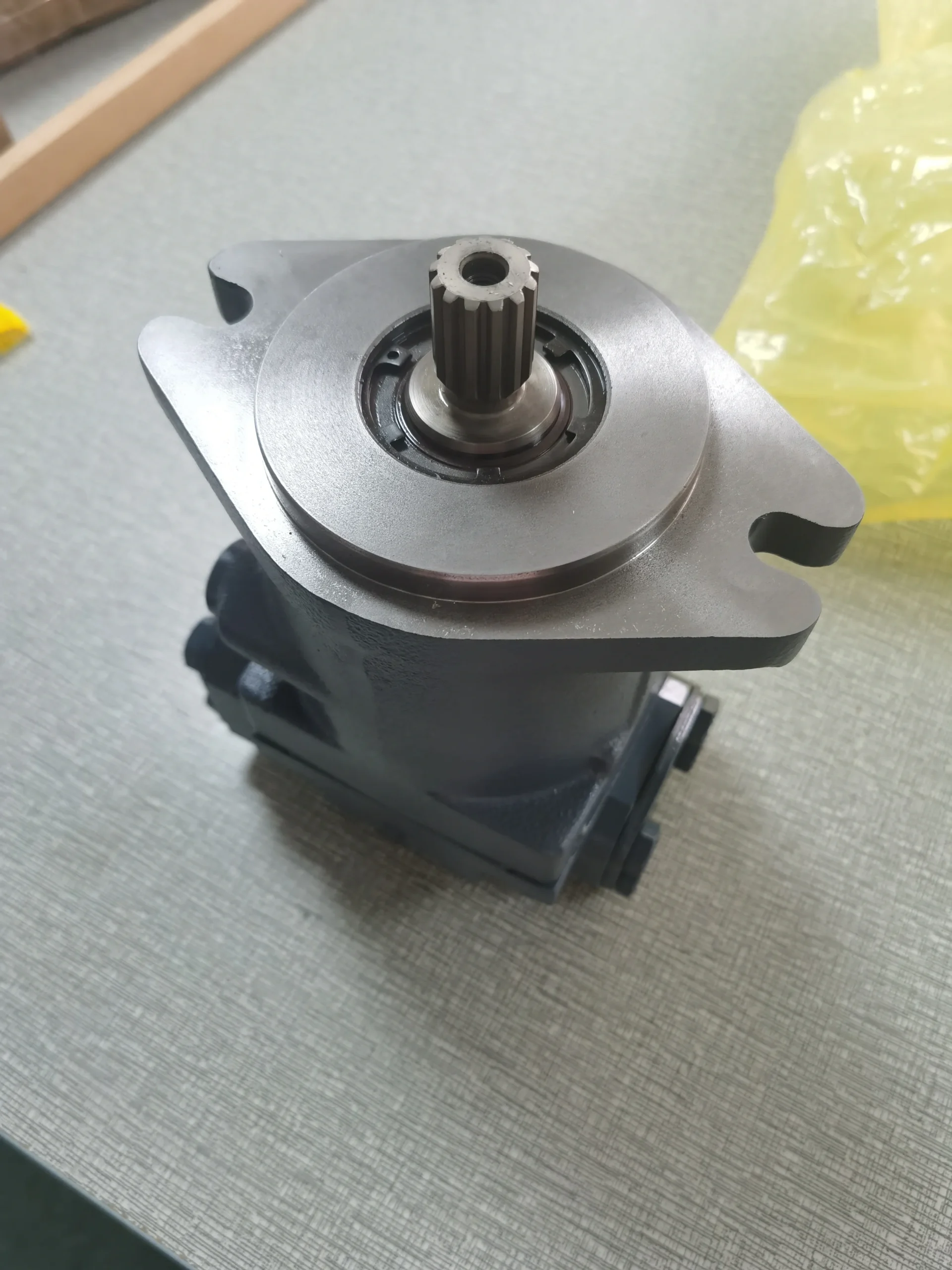
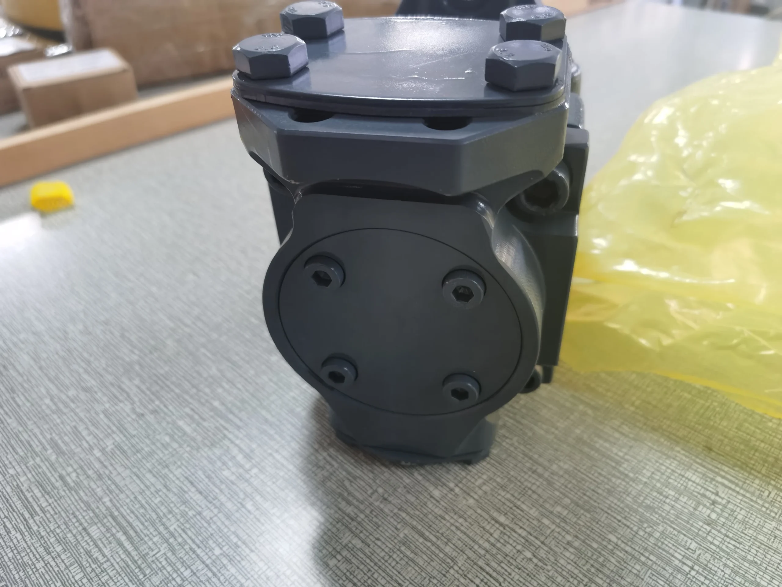
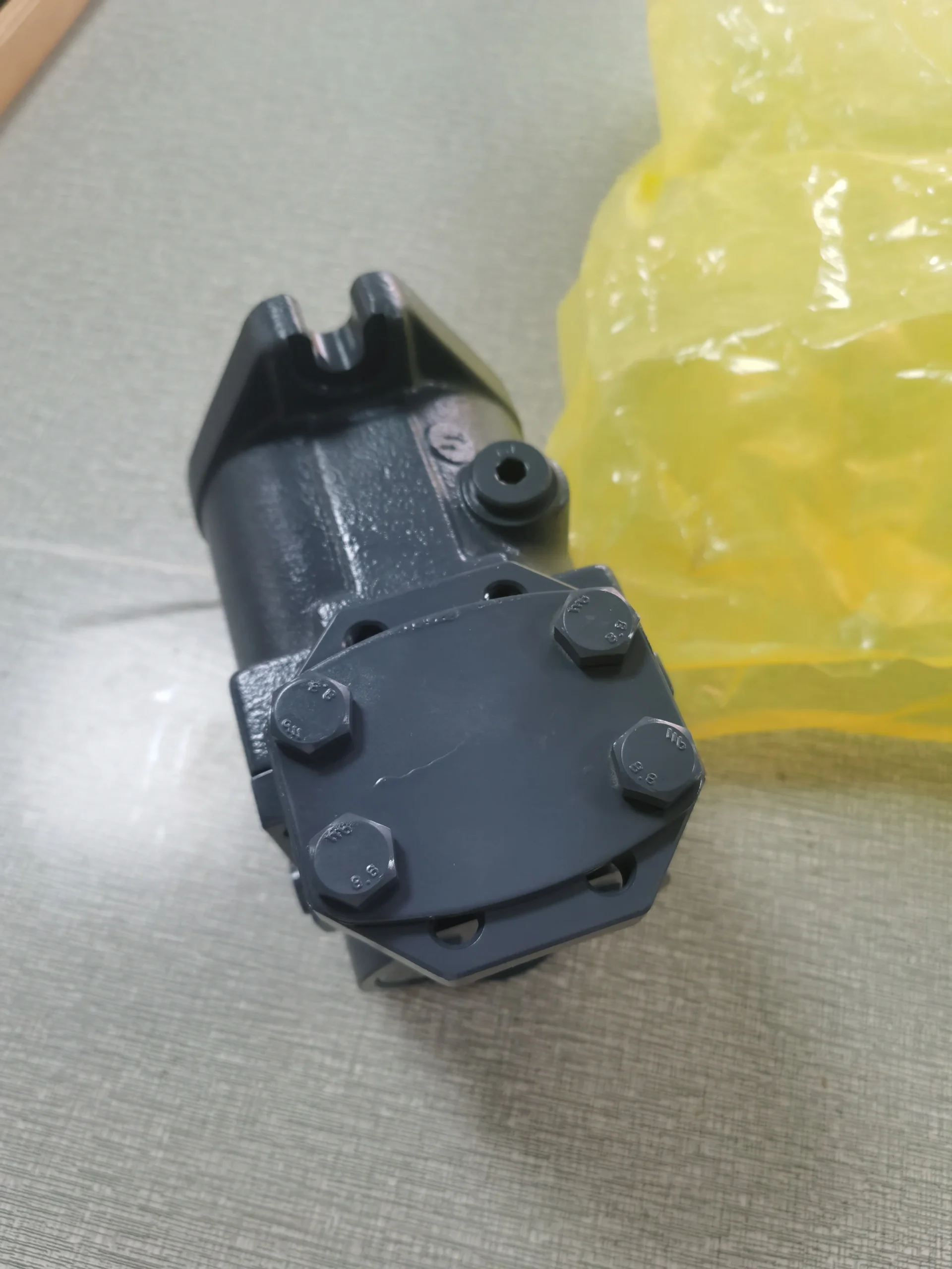

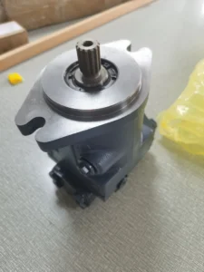
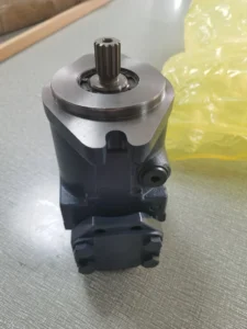

A4FO22/32R-NSC12K01 A4FO22/32R-NSC12N00 Hydraulic Axial Piston Pump OEM A4FO22 A4FO28 A4FO40 A4FO56 A4FO71 A4FO125 A4FO250
1. Basic performance parameters- Pump body type: Axial piston fixed displacement pump, integrated with high-pressure relief valve and pressure compensation valve, supports unidirectional rotation, suitable for medium and low pressure medium and small flow hydraulic systems
– Displacement and pressure parameters: Rated displacement 22 cc/rev (the “22” in the model corresponds to the displacement specification), quantitative output without variable adjustment; The rated working pressure is 160 bar, the maximum allowable pressure is 210 bar (short-term ≤10 seconds), the back pressure of the return oil is ≤3 bar, and the set pressure of the relief valve is 160 bar±5%
– Speed and flow parameters: Rated speed 3000 rpm, maximum speed 3600 rpm (short time ≤5 minutes), minimum stable speed 600 rpm; The output flow rate at the rated speed is 66 L/min (22 cc/rev×3000 rpm÷1000), and the flow pulsation rate is ≤2%
– Efficiency parameters: Rated working condition volumetric efficiency ≥92%, total efficiency ≥85%; The pressure loss at rated flow is no more than 4 bar, and the idle power consumption is no more than 500 W
2. Structure and connection parameters
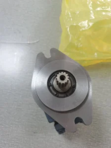
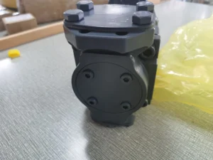
– Structural type: Cast iron pump body, surface phosphating anti-rust treatment; Alloy steel plunger (hardness HRC60-63), aluminum alloy cylinder body (hard surface anodized), nitrided treatment swash plate, double-end mechanical seal + lip seal combination; The spring-return type plunger return mechanism is adopted to ensure reliable oil suction at low speeds
– Installation and connection specifications: Flange installation (compatible with ISO 3019-1 standard, “NSC12K01” corresponds to right-rotating installation positioning); Oil port threads: Suction port G1, outlet port G3/4, control port G1/8; The output shaft is connected by a flat key (specification 8×20). The overall weight is approximately 7 kg, and the external dimensions (length × width × height) ≈260×180×150 mm
– Protection grade: IP64, suitable for dusty environments of small and medium-sized industrial equipment and light-load construction machinery
3. Medium and Environmental requirements
– Medium requirements: Compatible with L-HM 32/46 anti-wear hydraulic oil, allowable medium viscosity range 10-300 mm²/s, moisture content ≤0.03%, solid particle size ≤10 μm
– Environmental parameters: Operating environment temperature -20℃ to 85℃, relative humidity ≤95%; The cleanliness of the oil should reach ISO 4406 14/11 grade
– Filtration requirements: A filter screen of ≥100 mesh should be installed on the oil suction side, and the filtration accuracy on the oil return side should be ≤25 μm. It is recommended to install a low-pressure filter (accuracy ≤10 μm).
Ii. Working Principle
This pump is an axial plunger quantitative pump. Its core achieves the stable conversion of mechanical energy into hydraulic energy through the mechanism of “plunger reciprocating volume change + relief valve pressure protection”. The specific process is as follows:
1. Core mechanism of power transformation
The motor drives the transmission shaft to rotate the cylinder block synchronously. Under the combined action of the thrust from the inclined surface of the swash plate and the return spring, the plunger moves back and forth in a straight line within the plunger holes of the cylinder block. When the plunger rotates with the cylinder body to the oil suction zone, it extends outward under the action of the return spring, increasing the volume of the plunger hole to form a vacuum. The hydraulic oil is then sucked in through the oil suction port and the oil suction chamber of the distribution plate. When the plunger rotates to the oil pressure zone, the swash plate compresses the plunger to retract inward, reducing the volume of the plunger holes. The oil is squeezed to generate pressure and guided through the oil pressure chamber of the distribution plate to the oil outlet for discharge, providing stable power for the actuating elements (cylinders, motors) of the hydraulic system.
2. Pressure protection mechanism
The integrated high-pressure relief valve is connected in parallel between the oil outlet and the oil suction port, serving as the core of the system pressure protection: when the system load increases and the pressure rises to the rated value of 160 bar, the valve core of the relief valve begins to open, guiding part of the oil back to the oil suction chamber. When the pressure exceeds the maximum allowable value of 210 bar, the relief valve is fully open to unload, preventing the pump body, pipelines and downstream components from being damaged due to overload. The pressure compensation valve works in conjunction with the distribution plate to reduce axial leakage and ensure that the volumetric efficiency remains stable at over 90% at different speeds.
Iii. Product Features and Advantages
– Quantitative stable fuel supply: Fixed displacement design of 22 cc/rev, rated flow rate of 66 L/min, output accuracy ±2%, flow pulsation rate ≤2%, suitable for medium and small load scenarios with high requirements for flow stability (such as precise feed, quantitative pressurization)
– Compact and lightweight structure: The cast iron pump body combined with the aluminum alloy cylinder weighs only 7kg, with dimensions of 260×180× 150mm. Compared with gear pumps of the same displacement, its volume is reduced by 20% and its weight by 30%, making it suitable for compact installation Spaces of small equipment
– High wear resistance and long service life: The alloy steel plunger is nitrided, and the surface polishing accuracy of the swash plate reaches Ra0.8μm. The wear of the key friction pair is ≤ 0.05mm per 10,000 hours. The static leakage of the double-seal combination design is ≤1 mL/min, and the fault-free operation life under rated conditions is ≥ 12,000 hours
– Low noise and easy maintenance: The modified swash plate curve optimizes the movement trajectory of the plunger. The operating noise at 1 meter is ≤70 dB, which is 3-5 dB lower than that of the plunger pump of the same displacement. The integrated relief valve eliminates the need for external valve groups. During maintenance, only the filter and seals need to be replaced regularly, reducing maintenance costs by 25%
Iv. Usage Functions and Purposes
1. Core usage functions
– Quantitative constant flow oil supply: It provides stable flow hydraulic oil for small and medium-sized hydraulic systems, serving as the power source for single or dual coordinated actuating elements to ensure consistent action speed
– System overload protection: The built-in relief valve precisely controls the maximum pressure of the system, replacing external pressure control components. This simplifies the system structure while avoiding overload damage
– High-efficiency power transmission: The total efficiency is ≥85%, which can efficiently convert the mechanical energy of small motors (3-5.5kW) into hydraulic energy. The power transmission loss is reduced by 10% compared with vane pumps of the same displacement
2. Main uses
As a core power component of medium and low pressure and small and medium flow hydraulic systems, it connects small and medium-sized motors with light-load/medium-load actuating elements, providing quantitative power for the stable operation scenarios of various small industrial machinery and light-load construction machinery. It is an economical and applicable core component of medium and small load hydraulic transmission systems.
V. Applicable Machines and Scenarios
1. Adapt to the core machine
– Industrial machinery: 100-300 ton small presses, 100-200 ton injection molding machines, CNC lathe hydraulic tool turrets, small fully automatic packaging machines, precision grinding machine feed systems
– Construction machinery: 3-5 ton small forklift lifting mechanism, micro excavator auxiliary action system, small loader steering system, hydraulic lawn mower cutting mechanism
– Special equipment: Small hydraulic lifting platforms, hydraulic adjustment systems for medical beds, precision press-fitting equipment for electronic components, small deck machinery for ships
2. Typical application scenarios
– Small press pressurization scenario: Equipped with a 200-ton small press, with a rated flow rate of 66 L/min to drive the pressurization cylinder, a downward speed of 80 mm/s, a pressurization pressure of 160 bar, a stable error of ≤1%, and a single pressurization cycle of 1.5 seconds, meeting the efficiency requirements for stamping and forming of hardware parts
– Forklift lifting scenario: As the power source of the 4-ton forklift lifting mechanism, it drives the lifting cylinder at a rated pressure of 140 bar, with a lifting speed of 0.8 m/s. When the load is 3 tons, it can lift continuously for 100 times without pressure attenuation. IP64 protection is suitable for dusty environments in warehouses
– Precision press-fitting scenario: Compatible with electronic connector press-fitting equipment, the quantitative flow rate ensures a stable press-fitting speed of 50 mm/s, the pressure control accuracy is ±2 bar, and the press-fitting depth error is ≤0.05 mm, meeting the precision assembly requirements of 3C products
Six. Similar models
1. Different models of the same series displacement
-A4FO16/32R-NSC12K01: Rated displacement 16 cc/rev, output flow 48 L/min, rated pressure 160 bar, suitable for ultra-small systems (such as micro test benches, medical bed adjustment), with a 15% smaller volume and a weight of approximately 5.5 kg
-A4FO28/32R-NSC12K01: Rated displacement 28 cc/rev, output flow 84 L/min, maximum pressure 210 bar, suitable for medium and small systems (such as 300-ton presses, 5-ton forklifts), with 27% stronger power than the original model
2. Models with the same displacement but different functions
-A4FO22/32R-NSC12K01-P: Model with pressure sensor interface, supporting real-time pressure monitoring, suitable for automation scenarios requiring pressure feedback (such as precision press-fitting), with a 25% higher cost
-A4FO22/32L-NSC12K01: Left-rotating installation model, suitable for equipment with limited motor rotation direction. The oil outlet direction is opposite to the original model, while other performances remain the same
-A4FO22/32R-NSC12K02: Foot mounting model, suitable for equipment without flange installation space. The mounting base plate complies with ISO 7005-1 standard, with an additional weight of 0.5kg
Vii. Precautions for Use
Installation and commissioning
When installing, ensure that the coaxiality error between the pump shaft and the motor shaft is ≤ 0.1mm. Use an elastic coupling for connection. It is strictly prohibited for radial force (≥ 80N) to directly act on the pump shaft to avoid uneven force on the swash plate, which may lead to accelerated wear
The oil suction pipeline should be short and straight (length ≤1.5 meters, diameter ≥20 mm), and the distance between the oil suction port and the bottom of the oil tank should be ≥100 mm to avoid excessive oil suction resistance causing cavitation. The pipeline connection adopts oil-resistant sealing gaskets to ensure a tight seal. A vacuum gauge (vacuum degree ≤0.02 MPa) can be installed on the oil-absorbing side.
Before the first start-up, hydraulic oil (about 10 mL) should be injected into the pump cavity, and the plunger should be manually turned 3 to 5 times to confirm that it can extend and contract flexibly. When starting up, first open the oil suction valve and run it no-load at low pressure (50 bar) and low speed (1000 rpm) for 20 minutes. Gradually increase it to the rated parameters and check the pressure setting value of the relief valve at the same time
When installed in a compact space, a heat dissipation space of ≥ 100mm should be reserved around the pump body. When the ambient temperature exceeds 40℃, ventilation should be enhanced to prevent the oil temperature from being too high and accelerating the aging of the sealing parts
2. Operation and Maintenance
During operation, the pump body temperature (normal ≤80℃, maximum ≤90℃), outlet pressure and noise should be monitored weekly. If the temperature rises sharply by more than 10℃, the pressure fluctuates by more than 5 bar or the noise exceeds 78 dB, stop the machine immediately for inspection. Focus on checking the cleanliness of the oil (once every three months), the wear of the plunger or the leakage of the seal
– Regular maintenance cycle: Replace the hydraulic oil and suction and return oil filters every 4,000 hours. Disassemble and inspect every 10,000 hours. Replace the plunger when the diameter wear is ≥ 0.1mm or the cylinder block hole is scratched, and replace the sealing parts at the same time. The pressure setting value of the relief valve should be calibrated with a pressure gauge every 2000 hours
– It is strictly prohibited to run the engine without oil (idling for more than 3 seconds can easily cause the plunger and cylinder block to be scratched). Do not operate for a long time at the maximum speed (3600 rpm) (no more than 10 minutes at a time). Before the system is shut down, it needs to be reduced to low pressure and run no-load for 3 minutes. After the oil temperature is ≤60℃, the oil source should be cut off
3. Storage and Protection
When stored for a long time, all oil ports should be sealed with special plugs. Anti-rust oil (about 20 mL) should be injected into the pump cavity, and lithium-based grease should be applied to the keyway of the output shaft. Store in a dry warehouse with a temperature ranging from 0 to 45℃ and a humidity of no more than 60%. Avoid direct sunlight and oil contamination. Manually turn the machine once every three months
Before putting the pump into use after being idle for more than six months, the pump cavity should be flushed with clean hydraulic oil and the sealing parts replaced. Run the low-speed no-load test for 10 minutes to check the pressure stability and leakage rate (≤1 mL/min is normal). Only after meeting the standards can it be connected to the system


