
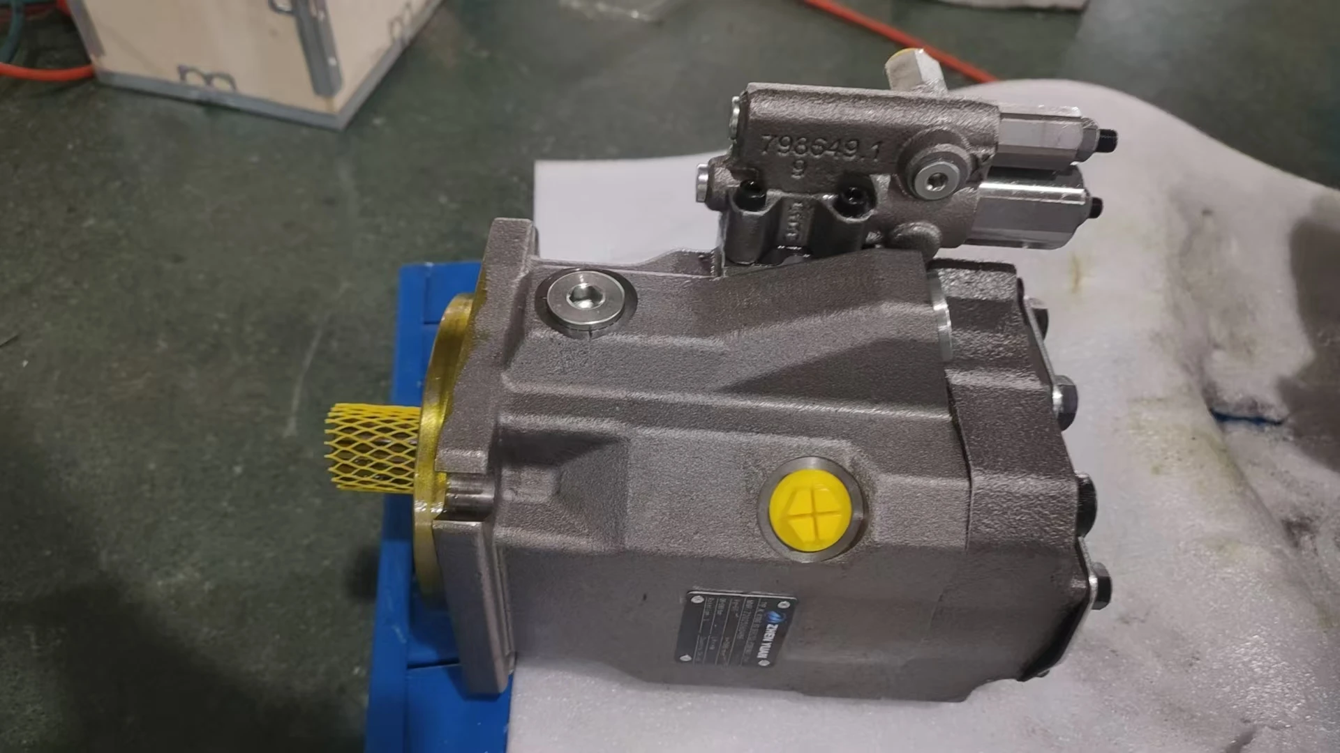


A10V060DR/52L-VSC12K68 Axial Piston Fixed Displacement Hydraulic Oil Pump A10VO 45 60 71 85
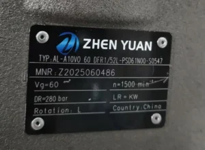
| Model Number | A10V060DR/52L-VSC12K68 |
|---|
Product Description
A10V060DR/52L-VSC12K68 Swash Plate Axial Piston Fixed Displacement Pump A10VO 45 60 71 85 Hydraulic Oil Pump OEM
1. Basic performance parameters- Pump body type: Open-circuit swash plate axial piston variable pump, integrated DR Type constant pressure control module and pressure cut-off device, supports unidirectional rotation, suitable for medium-pressure industrial hydraulic control systems
– Displacement and pressure parameters: Rated displacement 60 cc/rev (” 60 “in the model indicates the core displacement), variable range 0-60 cc/rev continuously adjustable; The rated working pressure is 315 bar, the short-term maximum allowable pressure is 350 bar (single continuous time ≤10 seconds), the constant pressure control setting range is 50-315 bar, and the pressure control accuracy is ±1.5% FS
– Speed and flow parameters: Rated speed 1800 rpm (compatible with standard industrial motor speed), maximum speed 2200 rpm (short time ≤5 minutes), minimum stable speed 500 rpm; The maximum output flow at the rated speed is 108 L/min (60 cc/rev×1800 rpm÷1000), the flow pulsation rate is ≤3.5%, and the constant pressure regulation response time is ≤180 ms
– Efficiency parameters: Rated working condition volumetric efficiency ≥94%, total efficiency ≥86%; The minimum displacement during the constant pressure and pressure-holding stage is ≤3 cc/rev, and the pressure-holding power consumption is reduced by more than 40% compared with the fixed displacement pump
2. Structure and connection parameters
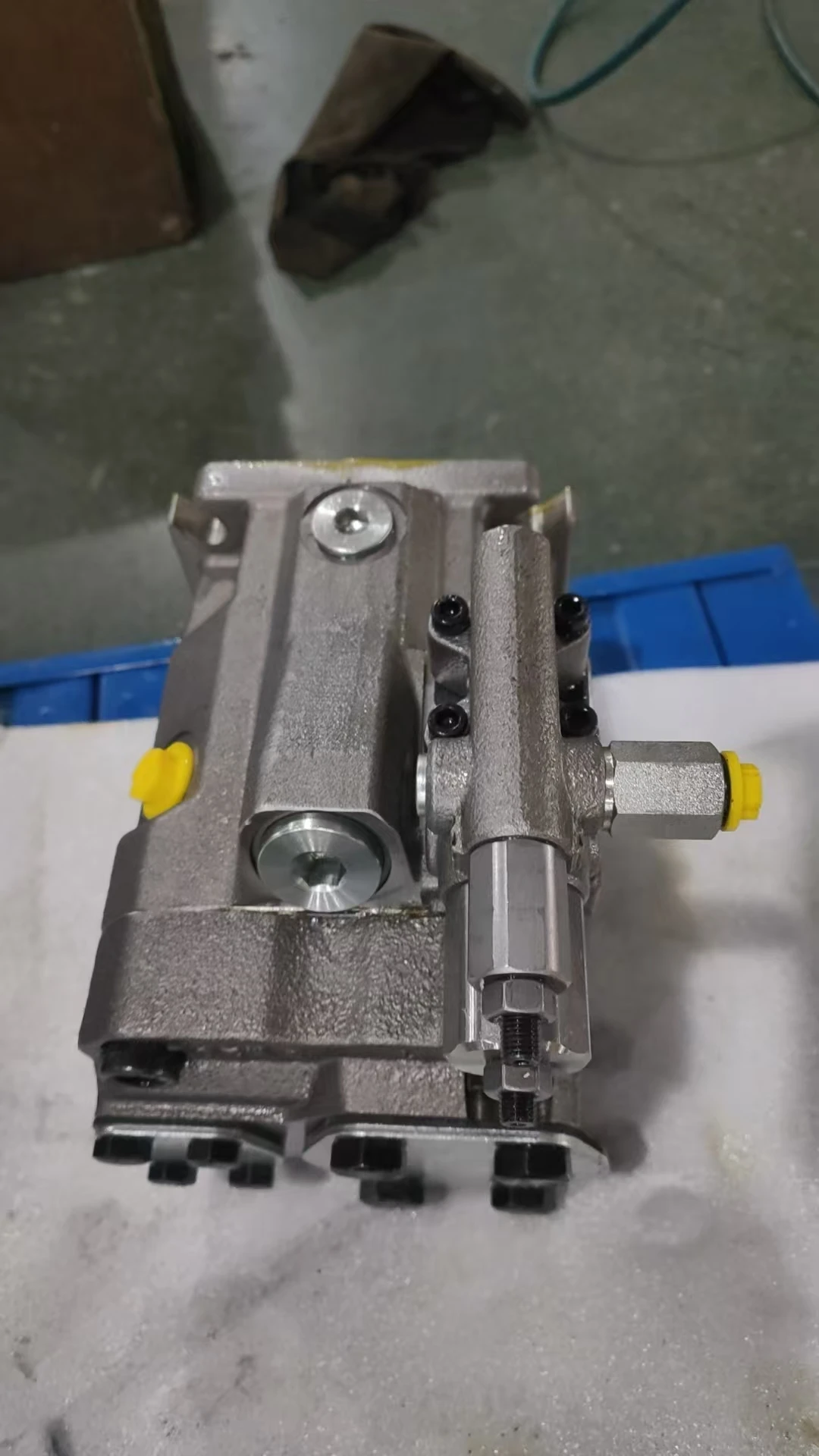
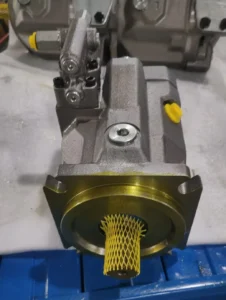
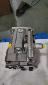
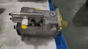
– Structural type: High-strength ductile iron pump body (tensile strength ≥350 MPa), with dual anti-rust treatment of phosphating and powder coating on the surface; The 7 plungers are evenly distributed in the cylinder body. The alloy steel plungers are nitrided (hardness HRC60-63), and the surface of the swash plate is plasmonized with a wear-resistant coating (hardness HV800-850). Static pressure balanced distribution plate, supported by double-row tapered roller bearings; The combination of skeleton mechanical seal and fluororubber lip seal has a static leakage rate of ≤0.8 mL/min. Integrated pressure compensation valve and anti-cavitation valve
– Installation and connection specifications: Flange installation (compatible with ISO 3019-1 standard, “52L” corresponds to installation positioning); Oil port thread: Suction port G1¼, high-pressure outlet port G1, control port G1/4 (X port); The output shaft is connected by a flat key (specification 12× 30mm, conforming to SAE J620 standard); The overall weight is approximately 28 kg, and the external dimensions (length × width × height) ≈360×220×200 mm, making it suitable for compact installation Spaces of industrial equipment
– Protection grade: IP65, suitable for dusty and slightly water-splashed environments in industrial workshops. It allows for horizontal or vertical installation (an oil absorption auxiliary device is required when installed vertically), and can withstand vibration acceleration ≤ 15g
3. Medium and Environmental requirements
– Medium requirements: Compatible with L-HM 46 anti-wear hydraulic oil. For low-temperature working conditions, L-HM 32 low-pour anti-wear hydraulic oil can be selected. The allowable medium viscosity range is 8-350 mm²/s, and the optimal working viscosity is 14-50 mm²/s. The moisture content should be ≤0.03%, and the contamination degree of solid particles should reach ISO 4406 15/12 grade. When matching with precision equipment, it should be upgraded to 14/11 grade
– Environmental parameters: Working environment temperature -25℃ to 85℃, optimal oil working temperature 45-65℃, short-term allowable ≤90℃ (≤30 minutes); Storage temperature: -40℃ to 100℃, relative humidity: ≤95% (no condensation). Adapt to an altitude of no more than 3000 meters. In high-altitude areas, the pressure of the vent plug needs to be adjusted
– Filtration requirements: A coarse filter screen of ≥80 mesh must be installed on the oil suction side (it is recommended to have a clogging alarm function). A high-pressure filter with an accuracy of ≤10 μm should be installed at the oil outlet, and a return oil filter with a filtration accuracy of ≤25 μm should be equipped on the return oil side. Before the first operation of the system, the pipeline should be flushed until the cleanliness meets the standard
Ii. Working Principle
This pump is an open-circuit swash plate axial piston constant pressure variable pump. The core converts mechanical energy into hydraulic energy through “piston reciprocating volume change +DR Type constant pressure variable regulation”, and is combined with pressure feedback and overload protection mechanisms to ensure system stability. The specific operation mechanism is as follows:
1. Core mechanism of power transformation
The industrial motor drives the pump shaft to rotate through an elastic coupling, which in turn rotates the cylinder and the plunger synchronously. Under the thrust of the inclined surface of the swash plate and the reset action of the return spring, the plunger moves back and forth along the plunger hole of the cylinder block in a straight line. When the plunger rotates with the cylinder block to the oil suction zone, it extends outward, increasing the volume of the plunger hole and creating a negative pressure vacuum. The hydraulic oil is then sucked in through the oil suction port, the coarse filter screen and the oil suction chamber of the distribution plate. When the plunger rotates to the oil pressure zone, the swash plate forces the plunger to retract inward, causing a sharp reduction in the volume of the plunger holes. The oil is compressed to generate high pressure and then delivered to the hydraulic actuator (cylinder, motor, etc.) through the oil pressure chamber of the distribution plate and the high-pressure filter, completing the power output. The output flow rate is positively correlated with the inclination Angle of the swash plate. The greater the inclination Angle, the longer the plunger stroke, and the greater the output flow rate.
2. Constant pressure variable and protection mechanism
The DR Type constant pressure control mechanism is adopted. The inclination Angle of the swash plate is adjusted in real time through the pressure feedback signal. When the system pressure rises to the set value, the pressure oil pushes the variable piston to move. Through the connecting rod mechanism, the swash plate reduces the inclination Angle, lowers the plunger stroke and output flow, and only maintains the minimum flow required for system leakage, achieving constant pressure and pressure holding. When the system pressure is lower than the set value, the reset spring pushes the variable piston to reset, the inclination Angle of the swash plate increases, and the flow rate rises to the rated value. It integrates a pressure cut-off function. When the system pressure exceeds the maximum limit of 350 bar, the pressure cut-off valve acts quickly to minimize the inclination Angle of the swash plate, and at the same time, the relief valve opens to unload, preventing the pump body and pipelines from overloading. The distribution plate adopts a self-compensation structure, which can automatically correct the wear clearance and maintain a stable volumetric efficiency. The anti-cavitation valve automatically replenishes oil when the suction pressure is too low to prevent cavitation damage.
Iii. Product Features and Advantages
– Precise and stable constant pressure control: The DR Type constant pressure control module ensures that the output pressure fluctuation is ≤1.5% FS, and the minimum displacement during the pressure holding stage is ≤3 cc/rev. Compared with ordinary variable pumps, the power consumption for pressure holding is reduced by more than 40%. The pressure setting range is continuously adjustable from 50 to 315 bar, catering to the pressure requirements of different processes, such as multi-stage pressure holding for injection molding machines and staged pressing for presses
– Strong medium-pressure adaptability: The rated pressure of 315 bar is suitable for most industrial medium-pressure systems, and the short-term pressure resistance capacity of 350 bar can cope with load shocks. The uniform distribution design of 7 plungers reduces flow pulsation (≤3.5%), and the operating noise at 1 meter is ≤75 dB, reducing system vibration and noise pollution
– ** Long service life and low loss ** : The nitrided plunger and the spray swash plate form a high-strength friction pair, with a fault-free operating life of ≥ 12,000 hours under rated conditions. The static leakage is ≤0.8 mL/min, which is 30% lower than that of pumps of the same type, reducing oil loss and heat generation. The double-sealed design enhances the anti-pollution ability and is suitable for dusty industrial environments
– Easy installation and maintenance: The standardized flange and oil port design are compatible with the installation dimensions of most industrial equipment, and there is no need to customize adapter parts. The modular valve group structure enables the replacement time of core components to be no more than 40 minutes, and maintenance can be completed on-site. Supports through-shaft drive and can be integrated with gear pumps to achieve multi-circuit oil supply, simplifying the system layout
Iv. Usage Functions and Purposes
1. Core usage functions
Constant pressure variable oil supply: Through the DR Type control mechanism, the pressure can be set steplessly from 50 to 315 bar. Once the pressure reaches the standard, it automatically reduces to the minimum flow rate for pressure holding, meeting the requirements of constant pressure conditions, such as hydraulic clamping devices and injection molding machine pressure holding circuits
– Pressure compensation regulation: When the system load changes and causes pressure fluctuations, the flow regulation is completed within 180 ms to return the pressure to the set value, ensuring the movement accuracy of the actuator, such as in the pressing process of a precision press
– Overload safety protection: Rapid unloading when pressure exceeds 350 bar, and anti-cavitation and anti-shock design to prevent pump body damage. When the motor is overloaded, the constant pressure mechanism automatically reduces the displacement to prevent the motor from burning out
– Multi-loop integrated drive: The through-shaft drive design allows for the installation of a gear pump or vane pump at the rear end of the output shaft to supply oil to auxiliary circuits (such as lubrication and cooling), reducing the number of power sources and saving installation space
2. Main uses
As the core power source of medium-pressure hydraulic systems in industry, it is used to convert the mechanical energy of motors into hydraulic energy, providing stable pressure and flow for various actuating components. It is widely compatible with equipment that requires constant pressure control and pressure-holding energy conservation. It is a key component of industrial equipment such as injection molding machines, presses, machine tools, and hydraulic presses, and is particularly suitable for hydraulic systems with multiple process stages and high pressure stability requirements.
V. Applicable Machines and Scenarios
1. Adapt to the core machine
– Plastic machinery: 150-300 ton injection molding machine clamping and pressure holding systems, small blow molding machine forming circuits, rubber vulcanizing machine pressure control circuits
Forging and pressing machinery: 300-630 ton medium and small-sized press pressing systems, main pressing circuits of hydraulic presses, and precision punch press slider drive systems
– Machine tool equipment: Heavy-duty lathe hydraulic chucks, milling machine worktable feed systems, grinding machine grinding wheel dressing hydraulic systems
– Other industrial equipment: power systems for hydraulic lifting platforms, lifting mechanisms for warehouse and logistics stackers, power sources for small hydraulic test benches
2. Typical application scenarios
– Injection molding machine pressure holding scenario: Compatible with 200-ton injection molding machines, the pressure is set at 120 bar during the injection stage, and the displacement is automatically maintained at 60 cc/rev (108 L/min) to achieve rapid mold filling. During the pressure-holding stage, the pressure rises to 150 bar, while the displacement drops to 3 cc/rev and only maintains the pressure. Within 10 seconds of pressure-holding, the pressure fluctuation is no more than 2 bar. The shrinkage rate of plastic products is reduced by 50%, and the energy consumption per shift is reduced by 35%
– Press pressing scenario: A 400-ton press is used to press thin metal sheets. The pressing pressure is set at 280 bar through constant pressure control. During the pressing process, the pressure fluctuation is ≤1.5 bar, and the thickness error of the sheet is ≤ 0.03mm. After the pressure reaches the set value, the displacement drops to 5 cc/rev, which saves 40% energy compared with the fixed displacement pump system and reduces the oil temperature by 10℃
– Machine tool chuck clamping scenario: It is used in the hydraulic chuck system of heavy-duty lathes. The clamping pressure is set according to the material of the workpiece (180 bar for steel parts and 80 bar for aluminum parts). The constant pressure mechanism maintains the pressure stability. The clamping force fluctuation is ≤3%. The radial runout during workpiece processing is ≤ 0.02mm, and the processing accuracy is improved by 20%
– Hydraulic test bench scenario: As the power source for the pressure resistance test bench of small and medium-sized hydraulic components, it can achieve pressure grading tests from 50 to 315 bar by adjusting the constant pressure setting value. The pressure control accuracy is ±0.5%, and it can automatically complete the component pressure holding test (pressure drop ≤1 bar after 30 minutes of pressure holding), with a test data repeatability error of ≤1%
Six. Similar models
1. Different models of the same series displacement
-A10V045DR /52L-VSC12K68: Rated displacement: 45 cc/rev, rated speed: 1800 rpm, flow rate: 81 L/min, rated pressure: 315 bar. Suitable for small equipment such as 100-150 ton injection molding machines and presses under 300 tons. Weight: approximately 22 kg, volume reduced by 20% compared to the original model
-A10V071DR /52L-VSC12K68: Rated displacement: 71 cc/rev, rated speed: 1800 rpm, flow rate: 127.8 L/min, maximum pressure: 350 bar, suitable for medium-sized equipment such as 300-500 ton injection molding machines and 630 ton presses. The power is 18% higher than the original model, and the weight is approximately 35 kg
-A10V031DR /52L-VSC12K68: Rated displacement 31 cc/rev, flow rate 55.8 L/min at rated speed 1800 rpm, rated pressure 315 bar, suitable for small machine tools, hydraulic fixtures and other light-load equipment, weighing only 18 kg, with a more compact structure
2. Models with the same displacement but different functions
-A10V060EP /52L-VSC12K68: Electric proportional control type, supports remote adjustment of pressure and flow by 4-20mA electrical signal, suitable for automated production lines and intelligent hydraulic systems, control accuracy ±0.5%, cost 45% higher than the original model
-A10V060LR /52L-VSC12K68: Constant power control type, maintaining a constant output power, with a hyperbolic relationship between pressure and flow, suitable for equipment with large load fluctuations (such as hydraulic shearing machines), can fully utilize the motor power, and the energy-saving effect is increased by 10% compared with the original model
-A10V060DFR /52L-VSC12K68: Dual-function type with constant pressure and flow control, capable of switching between constant pressure and constant flow modes, suitable for various working conditions equipment (such as multi-functional hydraulic test benches), enhanced flexibility, but the cost is 30% higher than that of the original model
Vii. Precautions for Use
Installation and commissioning
When installing, it is necessary to ensure that the coaxiality error between the pump shaft and the motor shaft is ≤ 0.05mm. Elastic couplings should be used for connection. Rigid connection or direct radial force (≥ 100N) acting on the pump shaft is strictly prohibited. The pump body fixing bolts are selected as 8.8 grade high-strength bolts, with a pre-tightening torque of ≥80 N·m to prevent loosening caused by operational vibration
The oil suction pipeline should follow the principle of “short, straight, thick + leak-proof” : length ≤1.2 meters, inner diameter ≥25 mm, and the distance from the oil suction port to the bottom of the oil tank ≥120 mm. The pipeline connection adopts high-pressure resistant sealing rings. The vacuum degree on the oil suction side is ≤0.02 MPa to prevent cavitation. When installed vertically, a check valve should be added to the oil suction port to prevent the backflow of oil
Before the first start-up, fill the pump chamber with clean hydraulic oil (about 300 mL), and manually turn the machine 4 to 5 times to confirm that the plunger can extend and contract smoothly. When starting, first idle at 800 rpm for 10 minutes without load, then increase to the rated speed and gradually load to the rated pressure. At the same time, calibrate the constant pressure setting value and the pressure cut-off value (it is recommended to calibrate once every 100 bar). After debugging, lock the adjustment knob to prevent accidental touch
Reserve a heat dissipation space of ≥ 150mm around the pump body. When the ambient temperature exceeds 40℃, a cooler needs to be installed. Before starting in northern winter, the hydraulic oil should be preheated to above 5℃ to avoid increased viscosity at low temperatures, which may cause starting wear. High-altitude areas (> 2000 meters) need to replace high-altitude ventilation plugs
2. Operation and Maintenance
During operation, key parameters need to be monitored in real time: pump body temperature (normal ≤80℃, maximum ≤90℃), outlet pressure (fluctuation ≤2 bar), and operating noise (≤75 dB). The industrial production line should be inspected every four hours. If the temperature rises sharply by more than 10℃, the pressure is abnormal or there is abnormal noise, the machine should be stopped immediately. The focus should be on checking the cleanliness of the oil, the jamming of the variable mechanism or the leakage of the seal
– Regular maintenance cycle: Under normal working conditions, replace the hydraulic oil and the three-stage filter every 1,500 hours. Replace every 800 hours in harsh working conditions such as dust and humidity. Disassemble and inspect every 8,000 hours. When the wear of the plunger is ≥ 0.03mm and the scratch of the swash plate is ≥ 0.02mm, it needs to be replaced. At the same time, replace the seal and the return spring. Calibrate the constant pressure control module and the pressure shut-off valve every 1200 hours
– Do not run without oil (running without oil for more than 3 seconds may cause column serra injury). Do not operate continuously at a pressure exceeding 350 bar (for no more than 10 seconds each time). When adjusting the constant pressure value, it should be operated under low pressure (≤50 bar) to avoid mechanism jamming caused by high pressure adjustment. Before shutting down, it should be reduced to low pressure and run no-load for 5 minutes. When the oil temperature is ≤60℃, the power should be cut off
3. Storage and Protection
When stored for a long time (more than 30 days), seal all oil ports with special plugs, inject special anti-rust oil (about 400 mL) into the pump cavity, and apply lithium-based grease to the keyway of the output shaft. Store at 0-40℃ and humidity ≤
Company Profile


Professional Manufacturer