

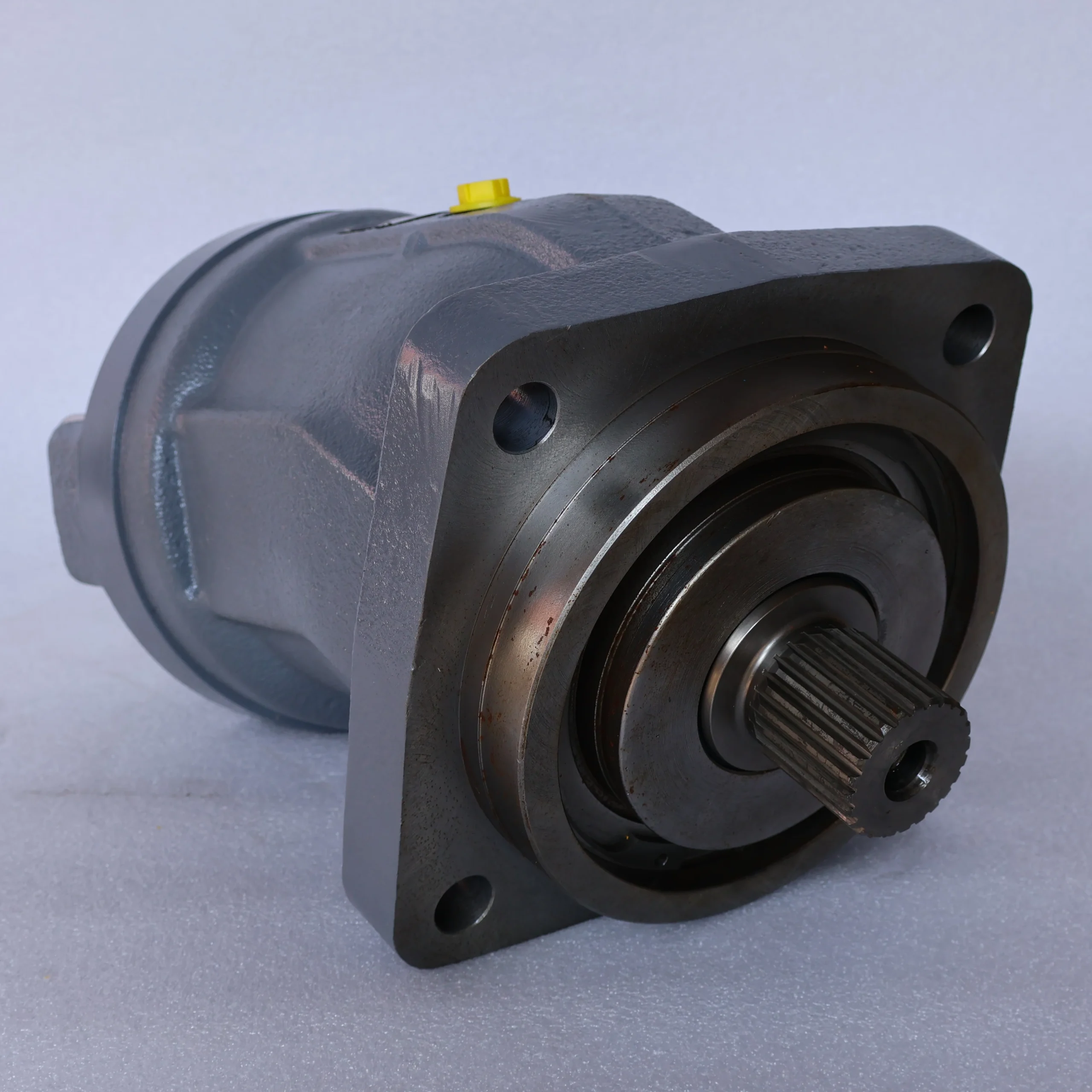

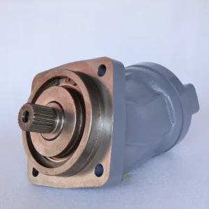
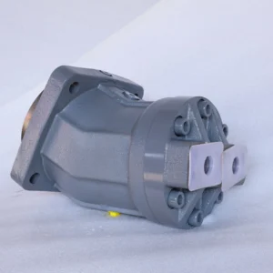


A2FM200/61W-VZB010 Hydraulic Piston Motor A2FM12 32 45 63 125 180 200 Axis Variable Displacement Motor A2FM200 A2FM180 OEM
Core performance parameters- Motor type: Inclined shaft axial piston quantitative motor, bidirectional rotation design, suitable for medium and high-pressure heavy-duty hydraulic systems, providing high-torque power source for large actuators.
– Displacement and pressure parameters: Rated displacement 200 mL/r; Rated working pressure: 31.5 MPa, maximum allowable pressure: 35 MPa (short-term ≤10 seconds); Rated speed: 1500 r/min, maximum speed: 2000 r/min (short-term ≤5 minutes), minimum stable speed: 20 r/min.
Torque and efficiency parameters: The rated torque at the rated speed is 1000 N·m, and the starting torque is ≥ 90% of the rated torque. Volumetric efficiency ≥93%, total efficiency ≥87%; Rated flow rate: 300 L/min (calculated by rated displacement × rated speed).
– Operating characteristics: Continuous operating oil temperature ≤85℃, rated working condition noise value ≤92 dB (measured at 1 meter); The fault-free operating life under rated conditions is ≥ 12,000 hours.
2. Structure and connection parameters
– Structural type: Inclined shaft axial piston structure, integrating high-strength alloy cast iron housing, reinforced piston pair, return plate, distribution plate and bidirectional oil replenishment valve; It adopts a pressure self-compensating seal and floating distribution plate design, with an internal mechanical brake (normally closed type), and the housing is equipped with an integrated heat dissipation oil circuit.
– Core material: The plunger is made of chromium-molybdenum alloy steel (surface nitrided treatment, hardness HRC60-64); The cylinder block is made of tin bronze ZCuSn10Pb6 (precision honing). The swash plate is made of alloy steel substrate + ceramic coating (hardness above HV900). The sealing part is a high-pressure resistant fluororubber combination (temperature resistance ≤110℃).
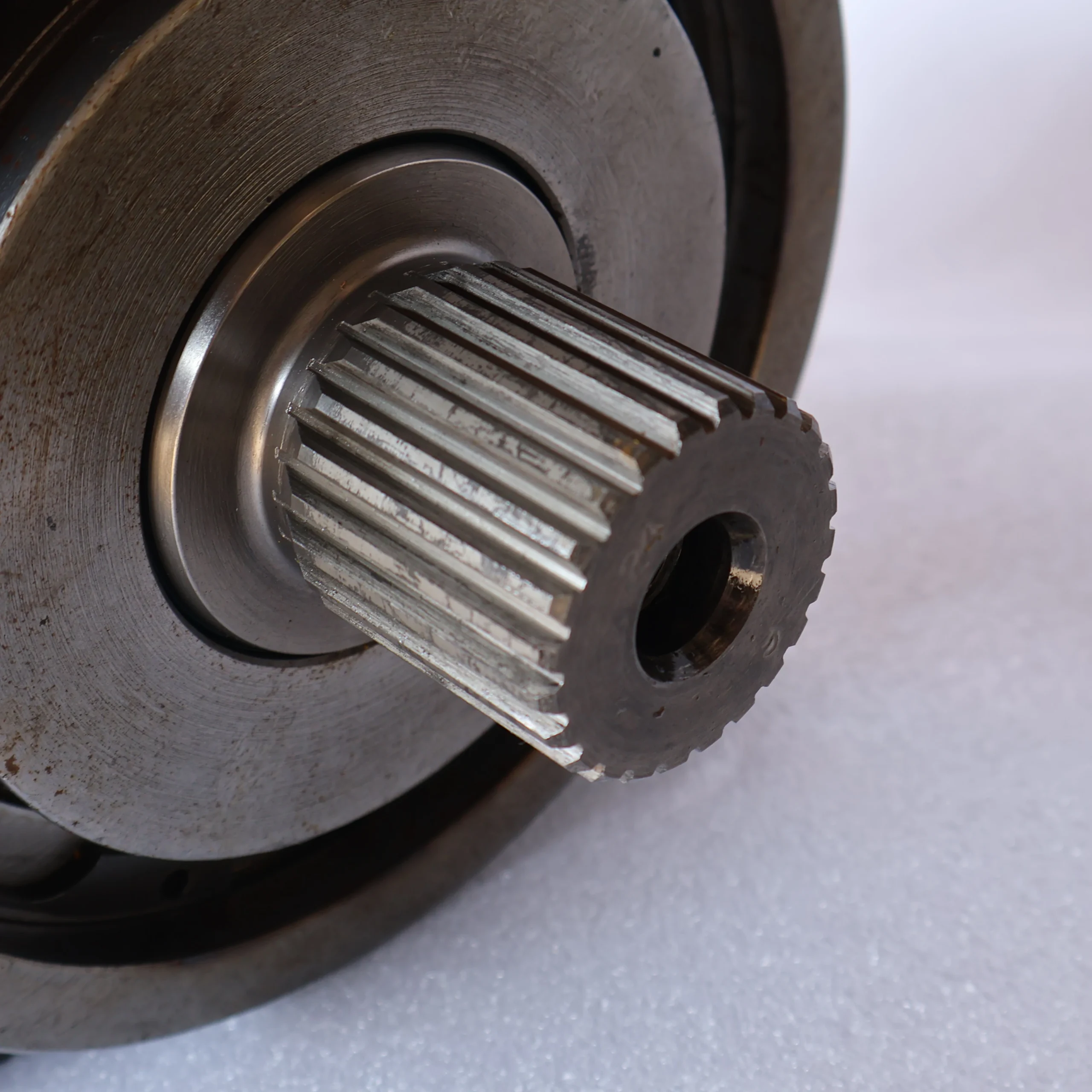
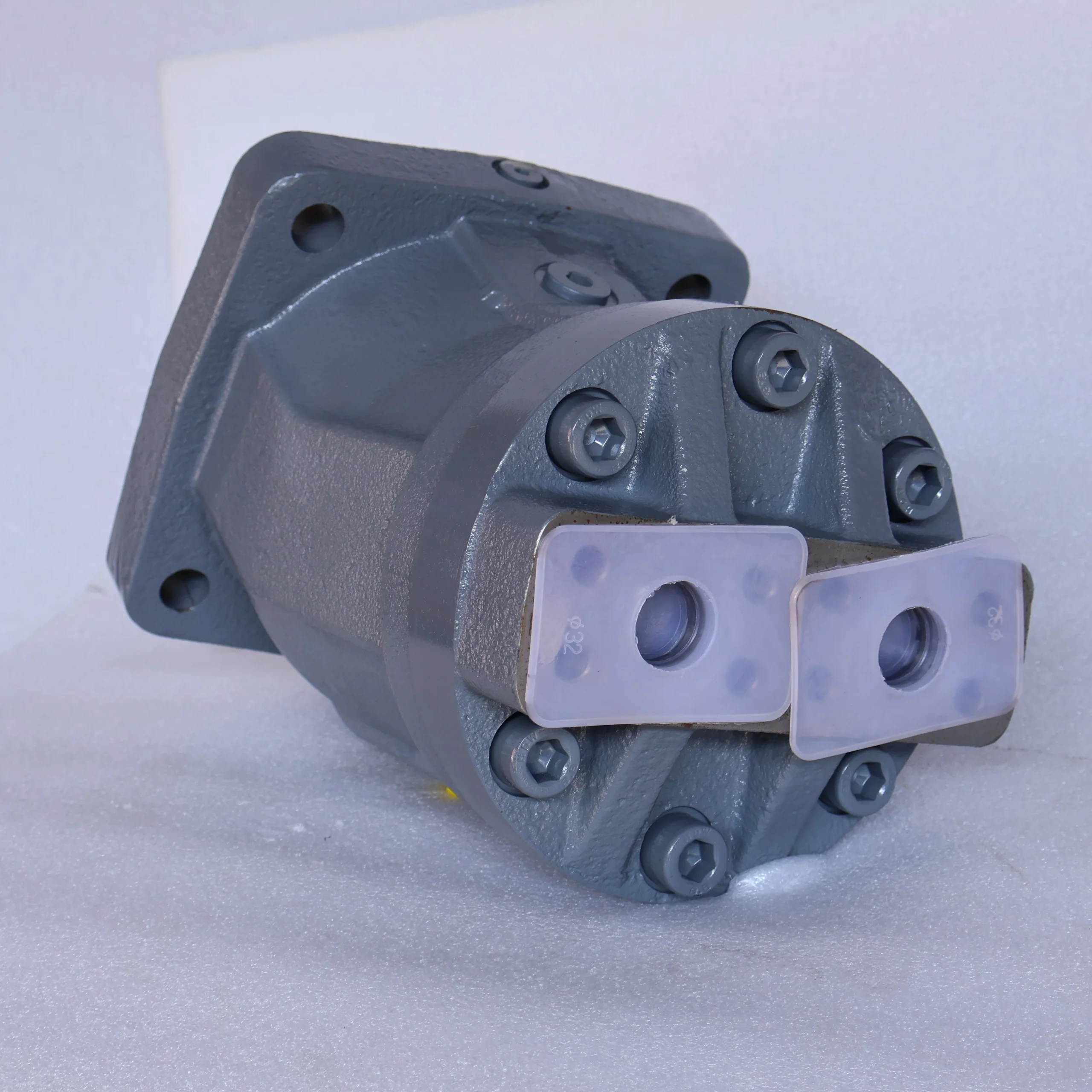
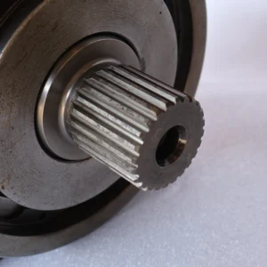
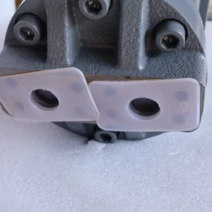
– Connection specification: Oil port flange connection (A/B working oil port is DN80, T return oil port is DN65); The output shaft is connected by involute splines (specification: 40×60). The installation method is flange installation (compatible with ISO 3019-2 standard). The weight is approximately 200 kg, and the external dimensions (length × width × height) ≈950×680×520 mm.
3. Medium and Environmental requirements
– Medium requirements: L-HM 46 anti-wear hydraulic oil is suitable for normal temperature. L-HM 32 is selected for low-temperature environment (below -20℃). The allowable medium viscosity is 12-400 mm²/s, moisture content is ≤0.02%, and solid particle size is ≤10 μm.
– Environmental parameters: The cleanliness of the oil should reach ISO 4406 15/12 grade, and a 10 μm filter should be placed before the oil inlet. The operating environment temperature ranges from -30℃ to 90℃, with a relative humidity of no more than 95%. The protection grade is IP67, making it suitable for heavy-duty scenarios such as construction machinery and mining equipment.
Ii. Working Principle
This motor is an inclined shaft axial piston quantitative motor. Its core converts hydraulic energy into mechanical energy through the mechanism of “high-pressure oil driving the piston to reciprocate – driving the cylinder to rotate – high-torque output”. The specific process is as follows:
1. Forward rotation process
High-pressure oil enters the motor housing cavity through port A and acts on the end face of the plunger. Due to the fixed inclination Angle of the motor’s inclined shaft, the plunger, under the combined action of high-pressure oil pressure and the constraint force of the return disc, drives the cylinder to rotate around the center of the output shaft. When the cylinder block rotates, it drives the spline output shaft to rotate synchronously, transmitting torque to the load. Meanwhile, the plunger on the other side resets in the low-pressure area, and the oil is discharged through Port B and Port T, completing the oil suction and discharge cycle. The built-in normally closed brake unlocks when powered on to ensure smooth rotation.
2. Bidirectional rotation process
When the high-pressure oil supply direction is switched to port B, the oil acts on the other end face of the plunger, driving the cylinder body to rotate in the opposite direction. The output shaft then outputs torque in the opposite direction. The low-pressure oil is discharged through Port A and Port T, achieving bidirectional equal torque rotation. During the rotation of the bidirectional oil replenishment valve, oil is supplied to the low-pressure area to prevent cavitation and ensure the stability of low-speed operation.
3. Braking and protection mechanism
When the system pressure exceeds 35 MPa, the matching relief valve automatically unloads to prevent the plunger and cylinder block from being damaged due to overload. When power is cut off, the built-in normally closed brake automatically locks the output shaft to achieve load positioning (braking torque ≥1200 N·m), preventing heavy objects from sliding down. The heat dissipation oil circuit is connected to the system’s cooling circuit, quickly removing frictional heat and maintaining a stable oil temperature.
Iii. Product Features and Advantages
– High torque density heavy-duty compatibility: With a displacement of 200 mL/r and a rated pressure of 31.5MPa, the rated torque reaches 1000 N·m. The torque density is 60% higher than that of gear motors of the same power. It is suitable for heavy-duty scenarios such as excavator rotation and crane luffing, and can drive loads over 30 tons to run smoothly.
– Wide speed stable operation: Speed range 20-2000 r/min. At the lowest stable speed of 20 r/min, the torque fluctuation is ≤3%, meeting the requirements of precise positioning. When the maximum rotational speed is 2000 r/min, the noise is only 92 dB, which is 5 dB lower than that of the plunger motor with the same torque.
– Excellent impact resistance and service life: The wear-resistant combination of reinforced plunger pairs and ceramic swash plates can withstand an impact pressure of up to 45 MPa, making it suitable for high-frequency impact conditions such as mining crushing. The pressure self-compensating seal design ensures a long-term stable volumetric efficiency of ≥93%, and a fault-free life under rated working conditions of ≥ 12,000 hours, which is 30% longer than that of ordinary plunger motors.
– Safety and convenient operation and maintenance: Built-in normally closed brake for self-protection in case of power failure, enhancing operational safety. Standardized flanges and splines are connected, which can directly replace products of the same specification. The key components are modularly designed, reducing the maintenance time by 50% compared with traditional motors.
Iv. Usage Functions and Purposes
1. Core usage functions
Medium and high-pressure heavy-duty drive: It outputs a high torque of 1000 N·m at a pressure of 31.5 MPa, replacing the “motor + reducer” combination. It is suitable for outdoor large equipment without stable power supply (such as mine loaders) or heavy-duty positioning scenarios (such as crane luffing).
– Bidirectional precise control: It can achieve forward and reverse rotation without an additional reversing mechanism, with a switching response time of ≤ 50ms. It is suitable for frequent reversing requirements such as “forward rotation for digging – reverse unloading” of excavators and “forward feeding – reverse retraction” of conveying equipment.
– Power-off safety braking: The built-in brake automatically locks when power is off, with a load positioning accuracy of ≤1°. It is suitable for scenarios such as aerial work platforms and crane booms that require fall prevention, without the need for additional braking devices.
2. Main application fields
In the field of medium and large-sized construction machinery: slewing mechanisms for crawler excavators over 30 tons, luffing mechanisms for truck cranes ranging from 25 to 40 tons, and traveling drives for bulldozers over 20 tons, all suitable for outdoor heavy-load operations.
– Industrial heavy-duty field: Roller drive for large metallurgical equipment, drive for heavy-duty conveying equipment, and actuator for hydraulic presses over 1,000 tons, suitable for continuous heavy-duty production scenarios.
– Mining and special fields: Travel drive for medium-sized mining loaders, rotating mechanism for heavy port handling equipment, mechanical drive for large ship decks, suitable for dusty and heavy-load scenarios.
V. Applicable Machines and Scenarios
1. Adapt to the core machine
– Construction machinery: 30-40 ton crawler excavators, 25-40 ton truck cranes, 20-30 ton bulldozers.
– Industrial equipment: Large metallurgical roller conveyors (diameter ≥ 800mm), heavy-duty belt conveyors (belt width ≥2 meters), 1000-1500 ton hydraulic presses.
– Special equipment: Medium-sized mine loaders (bucket capacity ≥3 m³), heavy-duty container cranes for ports, large ship anchor machines.
2. Typical application scenarios
– Excavator rotation scene: As a rotary motor for a 35-ton crawler excavator, when the input pressure is 31.5 MPa and the flow rate is 300 L/min, the output speed is 150 r/min and the torque is 1000 N·m, driving the rotary platform to rotate smoothly at 360°. The positioning accuracy is ≤1°. With IP67 protection, it is suitable for the dusty environment of mines and can operate continuously for 12 hours a day without failure.
– Crane luffing scenario: Equipped with a 30-ton truck crane luffing mechanism, with an output torque of 950 N·m and a rotational speed of 50 r/min, it only takes 15 seconds to drive the boom to rise from horizontal to 80°. When power is off, the brake locks and the boom does not descend, meeting the safety requirements for high-altitude operations.
– Mine scraper drive scenario: Drive a 3.5m ³ mine scraper to move, with an output pressure of 30 MPa, a rotational speed of 200 r/min, and a traction force of 150 kN. It can still operate stably under oil conditions containing rock cuttings, maintaining a volumetric efficiency of over 92%, and can work for an average of 28 days per month without any downtime due to faults.
Six. Similar models
1. Alternative models of the same series
-A2FM160/61W-VZB010: A medium-displacement model of the same structure, with a rated displacement of 160 mL/r and a rated torque of 800 N·m. The pressure parameters are consistent. It is suitable for 25-30 ton excavators and 20-25 ton cranes, and the cost is 25% lower than that of the original model.
-A2FM250/61W-VZB010: A large-displacement model of the same series, with a rated displacement of 250 mL/r and a rated torque of 1250 N·m. The pressure parameters are the same. It is suitable for excavators and cranes over 40 tons. The cost is 40% higher than that of the original model.
2. Cross-series alternative models
-A2FM200/63W-VZB010: High-pressure enhanced model, with a rated working pressure of 35 MPa, consistent displacement and torque parameters, suitable for ultra-high pressure crushing scenarios in mines. The cost is 30% higher than that of the original model.
-A2FM200/61W-VZB020: Brakeless model, suitable for drive scenarios that do not require positioning (such as conveyor roller tracks), with a cost 20% lower than the original model.
-A2FM200/61W-VZB010-D: Low-temperature compatible model. The sealing parts are made of low-temperature resistant fluororubber. The working temperature range is -40℃ to 90℃. It is suitable for construction machinery in extremely cold regions. The cost is 35% higher than that of the original model.
Vii. Precautions for Use
1. Medium and Selection management
– Strictly select L-HM 32/46 anti-wear hydraulic oil. It is strictly prohibited to mix oils of different grades or use inferior oils with corrosiveness and high moisture content. Select the model based on the system pressure (≤31.5 MPa) and torque requirement (≤1000 N·m). It is strictly prohibited to use beyond the parameters to avoid excessive wear of the plunger and cylinder block.
Before the new system is used for the first time, the pipelines and motor cavity should be flushed with clean oil in a circulating manner for more than 180 minutes to remove the remaining iron filings and welding slag from the installation. The diameter of the oil inlet pipeline should be no less than 80mm and the length no more than 3 meters to avoid excessive oil inlet resistance causing cavitation.
2. Installation and commissioning
Before installation, confirm the direction of the oil port (A/B is the bidirectional working port, and T is the return oil port). It is strictly forbidden to connect them in reverse to cause the motor to be stuck. The output shaft is connected to the load by an elastic coupling, with a coaxiality error of no more than 0.1mm, to prevent the plunger from breaking due to uneven loading.
Before debugging, manually rotate the wheel 3 to 5 times to ensure there is no jamming or abnormal noise. When starting for the first time, first introduce low-pressure oil (5 MPa) and run at low speed (300 r/min) without load for 40 minutes. Gradually increase the pressure and speed to the rated level, and check the smoothness of rotation and leakage (a leakage of ≤5 mL/min at the rated pressure is normal). The reliability of unlocking when powered on and braking when powered off of the brake needs to be tested.
When installed outdoors or in mines, apply oil-resistant sealant to the flange connections and do a good job of waterproofing the electrical interfaces. Reserve a heat dissipation space of ≥ 200mm around the motor and avoid proximity to high-temperature components.
3. Operation and Maintenance
During operation, monitor the motor housing temperature (normal ≤80℃, maximum ≤90℃), output torque and noise weekly. If the temperature rises sharply by more than 15℃, the torque drops by more than 10%, or the noise abnormally increases (> 100 dB), stop the machine immediately for inspection, with a focus on checking the oil contamination level, plunger wear or brake jamming.
– Regular maintenance every 6,000 hours: Disassemble and clean the housing, and check the gap between the plunger and the cylinder block (replace when > 0.02mm). Replace the seals, distribution plates and filters, adjust the clearance of the brake, reassemble and test the rotational speed and torque to ensure compliance.
– Do not run without oil (running without oil for more than 3 seconds may cause the plunger to sinter). It is strictly prohibited to operate at an excessive speed (> 2000 r/min) for a long time. Before shutting down, first run at low speed without load for 5 minutes. Wait until the oil temperature drops below 60℃, then cut off the oil supply to ensure the brake is reliably locked.
4. Storage protection
When stored for a long time, all oil ports should be sealed with special plugs, anti-rust oil should be injected into the housing, and lithium-based grease should be applied to the splines of the output shaft. The brake should be in the locked state and stored in a dry warehouse with a temperature ranging from 0 to 45℃ and a humidity of no more than 60%. It should be protected from direct sunlight, heavy object compression and corrosive gas erosion. Manual turning of the brake should be carried out once every three months.
Before being put into use after being idle for more than 18 months, thoroughly clean the inner cavity and replace all the seals. Conduct a power-on test on the brake, add new oil and run it at low speed for 30 minutes to check the smoothness of rotation, leakage and braking reliability. Only after meeting the standards can it be connected to the system.


