

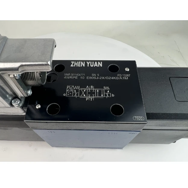
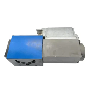
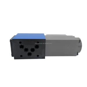

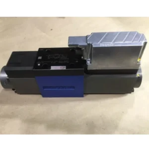
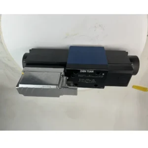
OEM 4WRPEH 4WRPEH10 4WRPEH6 Servo Hydraulic Valve 4WRPEH10C4100L-2X/G24K0/A1M Hydraulic Proportional Directional Valve
This proportional valve is a high-flow electro-hydraulic proportional directional control valve, integrating pilot control, position feedback and pressure compensation functions. It is suitable for the precise control scenarios of direction and flow in medium and high-pressure high-flow hydraulic systems. The specific technical parameters are as follows
– Pressure parameters: Rated working pressure 315bar, peak pressure 400bar (duration ≤5 seconds), return oil back pressure ≤50bar, pressure compensation adjustment range 50-315bar
– Flow performance: The maximum flow through at rated pressure is 100L/min, with a flow control accuracy of ±2% at full scale. The flow adjustment range is steplessly adjustable from 0 to 100%, and the flow stability deviation is ≤3% when the load changes
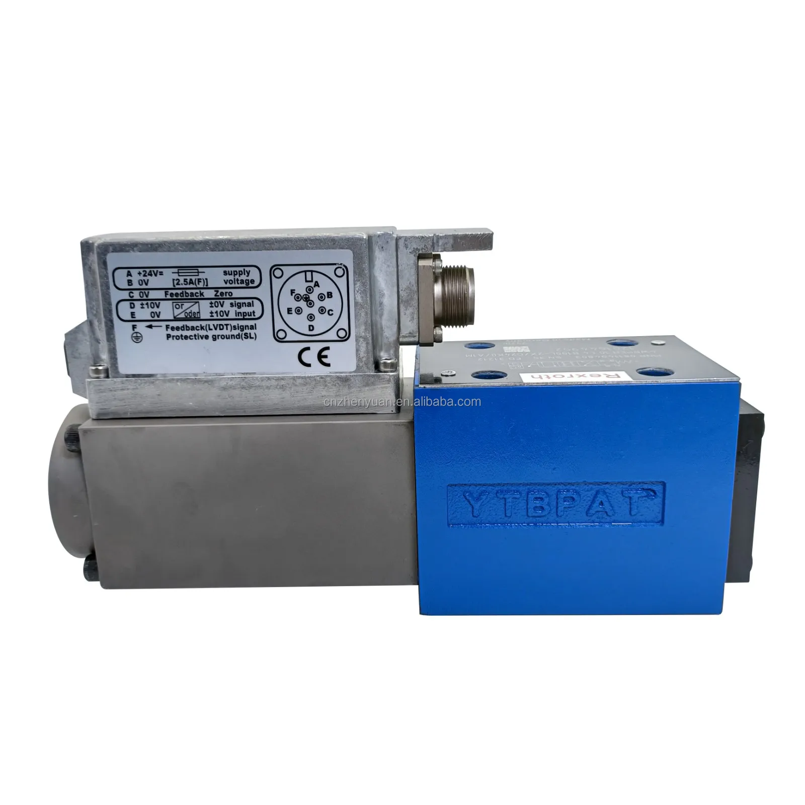
– Control signal: The proportional control signal supports 4-20mA (current type) or 0-10V (voltage type), and the valve core position feedback signal is 4-20mA. The control accuracy is ±0.5%
– Power supply parameters: Pilot control voltage 24V DC, allowable fluctuation range ±10% (21.6V-26.4V), rated power approximately 15W, standby power consumption ≤2W
– Response performance: The response time of the valve core from the 0 position to the maximum stroke is ≤80ms, the reversing switching time is ≤40ms, and the overshoot under step signals is ≤5%
– Compatible medium: mineral oil hydraulic oil, synthetic ester hydraulic oil, viscosity range 10-680mm²/s, oil cleanliness requirement NAS 7 grade
– Operating temperature range: Ambient temperature -20℃-80℃, valve body temperature rise ≤70K (under rated conditions), low-temperature start-up temperature ≥-30℃ (when suitable for low-temperature oil)
– Insulation and Protection: Insulation class F, insulation resistance ≥500MΩ (under normal temperature and humidity); Protection grade IP65, resistant to low-pressure jet water and dust
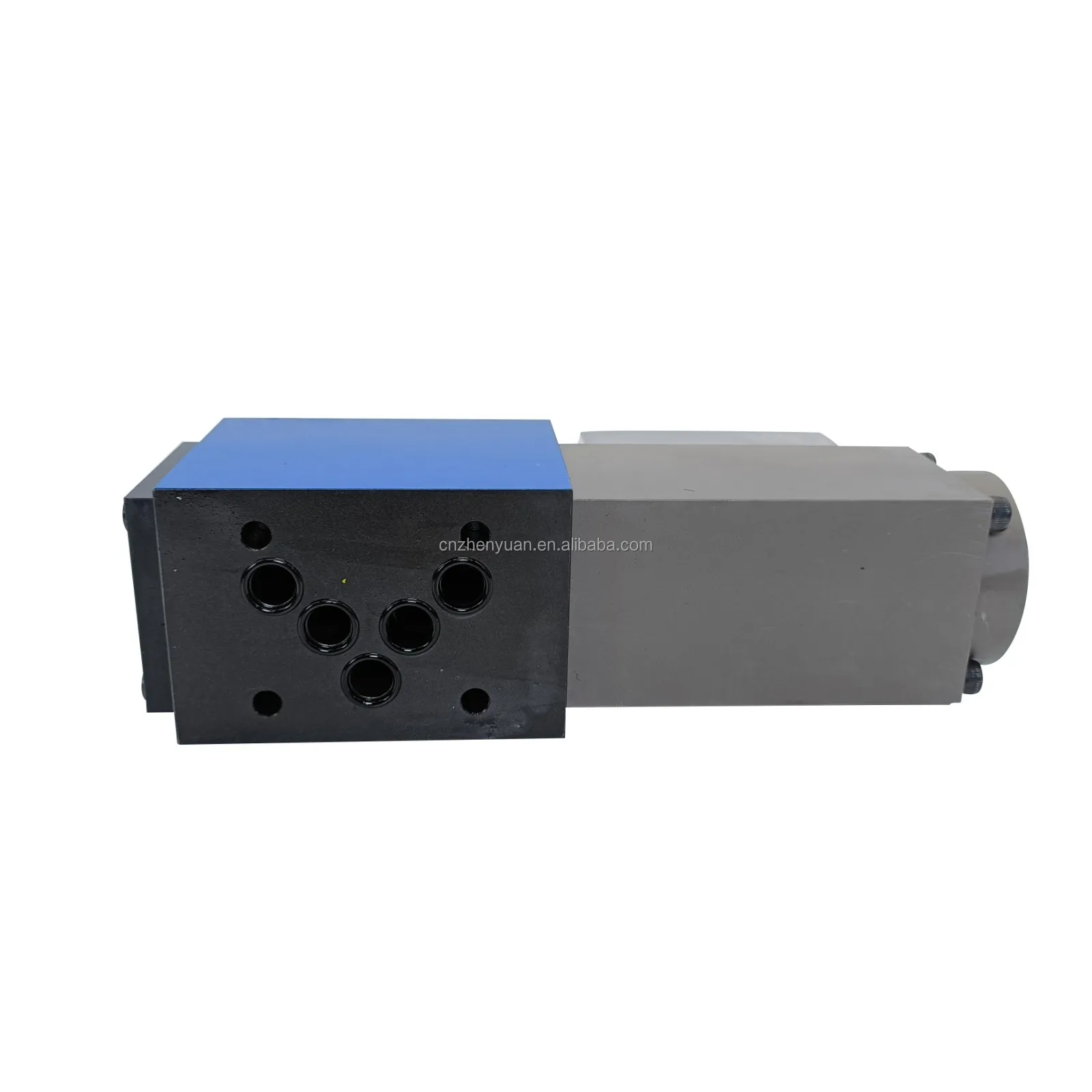
– Installation method: Plate installation, in compliance with ISO 4401-05 standard installation dimensions, installation surface roughness Ra≤1.6μm, installation bolt specification M12
– Leakage: The leakage at rated pressure is ≤0.5mL/min, and the increase in leakage after continuous operation for 2000 hours is ≤20%
– Service life: Continuous working life under rated conditions ≥ 12,000 hours, reversing cycle life ≥ 800,000 timesIi. Working Principle
This proportional valve is based on the principle of electro-hydraulic proportional closed-loop control. It controls the displacement of the main valve core through the electromagnetic force of the pilot stage, and combines position feedback and pressure compensation to achieve precise regulation under large flow rates. The core working process is as follows:
The core of the valve body is composed of the main valve module (high-flow main valve core, valve sleeve, reset spring), pilot control module (proportional electromagnet, pilot valve core), position feedback module (linear displacement sensor), and pressure compensation module. The proportional signal (4-20mA/0-10V) output by the controller acts on the proportional electromagnet. The electromagnet generates an electromagnetic force proportional to the signal strength, pushing the pilot valve core to overcome the spring force and move, regulating the pressure difference of the pilot control oil, and thereby driving the main valve core to move smoothly along the axial direction of the valve sleeve.
The displacement of the main valve core directly determines the opening degree of the main valve port and the flow direction: when the main valve core moves towards the A chamber side, Port P and Port A are connected, and Port B and port T are connected. The oil flows in the direction of “A in, B back “, and the flow rate increases linearly with the increase of the valve port opening. When moving towards the B cavity side, the oil flows in the opposite direction. When the valve core is in the middle position, the P/A/B/T ports interlock to achieve pressure holding. The position feedback module collects the position signal of the main valve core in real time and feeds it back to the controller, forming a closed-loop control to ensure that the position of the valve core precisely matches the command signal. The pressure compensation module monitors the pressure difference between the inlet and outlet in real time. By adjusting the pressure of the pilot oil, it corrects the opening degree of the main valve core, maintaining a stable flow rate when the load fluctuates and avoiding pressure shock under large flow rates.
Iii. Product Features and Advantages
This proportional valve integrates a high-flow optimized structure with precise closed-loop control technology. It is designed for medium and high-pressure high-flow working conditions and features the following core characteristics and advantages:
– High-flow precise control: With a high-flow capacity of 100L/min, it is suitable for heavy-duty systems. The flow control accuracy is ±2% and the position control accuracy is ±0.5%. Within the 0-100% flow range, the linearity deviation is ≤1.5%, solving the pain point of low regulation accuracy at high flow rates
– Stable and reliable pressure compensation: Equipped with an internal pressure compensation module, when the load pressure fluctuates within the range of 50 to 315bar, the flow stability deviation is ≤3%, making it suitable for complex working conditions such as parallel operation of multiple actuators or sudden load changes
– Strong high-pressure impact resistance: The main valve core is forged from high-strength alloy (tensile strength ≥1200MPa), and the valve sleeve is nitrided and hardened (hardness HV800 or above). It does not deform at a rated pressure of 315bar and can withstand short-term impact at a peak pressure of 400bar
– Response performance adapted to high flow rates: The optimized pilot-main valve flow matching design ensures a response time of ≤80ms and a reversing switching time of ≤40ms. Even under high flow conditions, it can still quickly respond to changes in operating conditions and suppress pressure shocks (shock pressure ≤420bar).
– Anti-pollution and low-noise design: The main valve core adopts a wide gap seal and self-cleaning valve port structure, which is compatible with NAS level 7 oil cleanliness. The valve port adopts A streamlined throttling design. Under rated working conditions, the noise is ≤78dB(A) (measured 1 meter away from the valve body).
– Wide environmental adaptability: With a wide operating temperature range of -20℃ to 80℃, it adopts high and low-temperature resistant fluororubber sealing parts, ensuring no jamming during low-temperature start-up and no aging of the sealing parts at high temperatures. The IP65 protection rating is suitable for outdoor dust and splash environments
– High integration and compatibility: Integrates proportional control, position feedback, pressure compensation, median pressure holding and manual emergency adjustment functions; Compatible with PLC and dedicated controllers, it supports dual signal input of 4-20mA/0-10V, simplifying system integration
– Excellent maintenance convenience: Modular structure design, proportional electromagnets, sensors, and seals can be replaced separately; Equipped with a diagnostic interface, it supports parameter calibration and fault code reading, reducing maintenance difficulty
Iv. Usage Functions and Purposes
The core function of this proportional valve is to linearly convert electrical signals into large-flow displacement of the main valve core, achieving directional switching and flow proportional regulation of the hydraulic oil. Control accuracy is guaranteed through position closed-loop feedback, and flow stability during load fluctuations is maintained through pressure compensation. It is equipped with auxiliary functions such as median pressure holding, overload buffering, manual emergency adjustment and fault diagnosis, which can meet the precise control requirements of action speed, direction and force output in high-flow hydraulic systems.
Its core application is to serve as the control core of medium and high-pressure high-flow hydraulic systems, providing precise direction and flow control for large hydraulic actuators (such as large-tonnage hydraulic cylinders and large-displacement hydraulic motors) or multi-actuator parallel systems, achieving stepless speed regulation, smooth reversing and precise positioning of the actuators. It is a key component for enhancing the degree of automation, operational efficiency and control accuracy of heavy equipment.
V. Applicable Machines and Scenarios
Based on its core features of large flow rate, high pressure adaptability and precise control, this proportional valve is widely adapted to the following heavy machinery and equipment as well as large flow conditions:
– Construction machinery: The active control circuit of the boom/bucket arm of large excavators, the hydraulic system of the luffing and telescopic boom of crawler cranes, large flow ensures rapid response of actions, and pressure compensation ADAPTS to the load fluctuations of compound actions
Heavy-duty machine tools and forging equipment: The worktable drive circuit of large CNC floor boring and milling machines, the main pressure cylinder and return control circuit of 1000-ton hydraulic presses, and precise flow control ensure processing accuracy and forming quality
– Plastic processing equipment: Main hydraulic circuits for mold closing, injection and melting of super-large injection molding machines (over 800 tons), with a large flow rate of 100L/min to meet the demand for rapid mold closing, and precise control of injection speed and pressure through proportional regulation
– Mining and metallurgical machinery: Lifting and pushing drive circuits for mine hydraulic supports, roller speed regulation systems for medium-sized steel rolling mills, anti-pollution and high-pressure characteristics suitable for harsh working conditions, stable energy supply to ensure continuous production
– Ports and lifting machinery: Hydraulic systems for hoisting and luffing of container quay cranes, mast lifting control circuits for large forklifts, large flow rates to meet high-speed hoisting requirements, and pressure compensation to ensure heavy-load safety
– Automated production lines: Hydraulic drive systems for multi-station heavy-duty stamping production lines, multi-actuator parallel control circuits for large-scale logistics sorting lines, and precise flow distribution adapted to the coordinated actions of multiple mechanisms
– Special vehicles: The ladder lifting hydraulic system of large fire engines and the walking drive circuit of crawler rescue vehicles, with wide temperature range and protection features, are suitable for complex outdoor working environments
Six. Similar models
This proportional valve belongs to the 4WRPEH series of high-flow electro-hydraulic proportional directional control valves. Similar models in the same series are mainly distinguished by diameter, flow range, control mode and adaptability to special working conditions. Common similar models include:
– Different diameter/flow rate models: 4WRPEH8C350L-2X/G24K0/A1M (diameter 8mm, flow rate 50L/min), 4WRPEH12C160L-2X/G24K0/A1M (diameter 12mm, flow rate 160L/min). The structure is the same, but the flow carrying capacity is different
– Pressure rating variant models: 4WRPEH10C4100L-2X/G24K0/A1M-P280 (rated pressure 280bar), 4WRPEH10C4100L-2X/G24K0/A1M-P350 (rated pressure 350bar), with consistent flow rates, suitable for systems of different pressure ratings
– Control mode optimization models: 4WRPEH10C4100L-2X/G24K0/A1M-LS (Load sensitive control), 4WRPEH10C4100L-2X/G24K0/A1M-M (manual + electronic control dual mode), suitable for different system control logics
– Special working condition compatible model: 4WRPEH10C4100L-2X/G24K0/A1M-L (Low-temperature type, resistant to -40℃), 4WRPEH10C4100L-2X/G24K0/A1M-EX (explosion-proof type) Ex d IIB T4), 4WRPEH10C4100L-2X/G24K0/A1M-W (waterproof type, IP67)
Vii. Precautions for Use
In light of the characteristics of high-flow and high-pressure working conditions, to ensure the service life and control accuracy of the proportional valve, the following matters should be noted during use:
– Installation Specifications: Before installation, thoroughly clean the installation surface, oil ports and pipeline welding slag/iron filings to prevent impurities from getting stuck in the main valve core. Connect strictly in accordance with the oil port marking (P/A/B/T). For large flow pipelines, flexible joints should be used to absorb vibration. The installation bolts should be evenly tightened diagonally (M12 bolts with a torque of 45-50N·m) to prevent deformation of the installation surface
– Oil management: Mandate the use of high-pressure anti-wear hydraulic oil with a cleanliness level of NAS 7 or above, and maintain a viscosity of 10-680mm²/s (46#/68# is recommended). Before the first operation, flush the pipeline with clean oil of the same specification (flushing accuracy ≥NAS 6 grade). Change the hydraulic oil every 2000 hours. Equip with a return oil filter with a filtration accuracy of ≤10μm and an oil suction filter with a filtration accuracy of ≤80μm. Regularly test the moisture content of the oil (≤0.1%).
– Electrical signal matching: The control signal must match the rated input of the valve body. When wiring, distinguish between positive and negative poles (DC 24V). The control circuit should be equipped with a surge absorber (resistant to 1.2kV impact) and a 1.5A fuse. For long-distance wiring (> 10m), shielded wires should be used to avoid signal interference
– Debugging and working condition control: Before debugging, reduce the system pressure to 0, slowly adjust the control signal (step size 5%), observe the flow/pressure changes, and ensure linear matching. Under rated operating conditions, the pressure does not exceed 90% of 315bar, and the rotational speed is adapted to the flow requirement to avoid throttling losses. Oil temperature control: -20℃ to 80℃. After low-temperature start-up, preheat to above 10℃ without load before loading. Start the cooling system when the oil temperature exceeds 75℃
– Maintenance and care: Check the sealing performance of the sealing parts every 1000 hours. Replace them in time if leakage is found (original factory high-pressure resistant sealing parts are preferred). Regularly clean the surface of the proportional electromagnet and the interface of the displacement sensor, and check the tightness of the terminal blocks. The control accuracy is calibrated through the diagnostic interface every month, and the wear clearance between the main valve core and the valve sleeve (allowable clearance ≤0.03mm) is inspected every six months.
– Fault handling: Flow fluctuation/reversing jam. First, check the cleanliness of the oil and the clogging of the filter. When the control signal is normal but the feedback is abnormal, detect the resistance value of the displacement sensor (normal 1-5kΩ) and the suction force of the proportional electromagnet. When performing maintenance, the system pressure must be completely released. Use special tools for disassembly. It is strictly prohibited to strike the main valve core or sensor. When replacing parts, accessories of the same specification should be selected. Arbitrary substitution is strictly prohibited
Storage requirements: Before long-term storage, drain the oil in the valve body, inject anti-rust oil and seal the oil port. Store in a dry and well-ventilated environment (temperature -5℃ to 40℃, humidity ≤70%), avoiding direct sunlight and rust caused by moisture. Manually push the valve core 2 to 3 times every 3 months to prevent the sealing parts from sticking together


