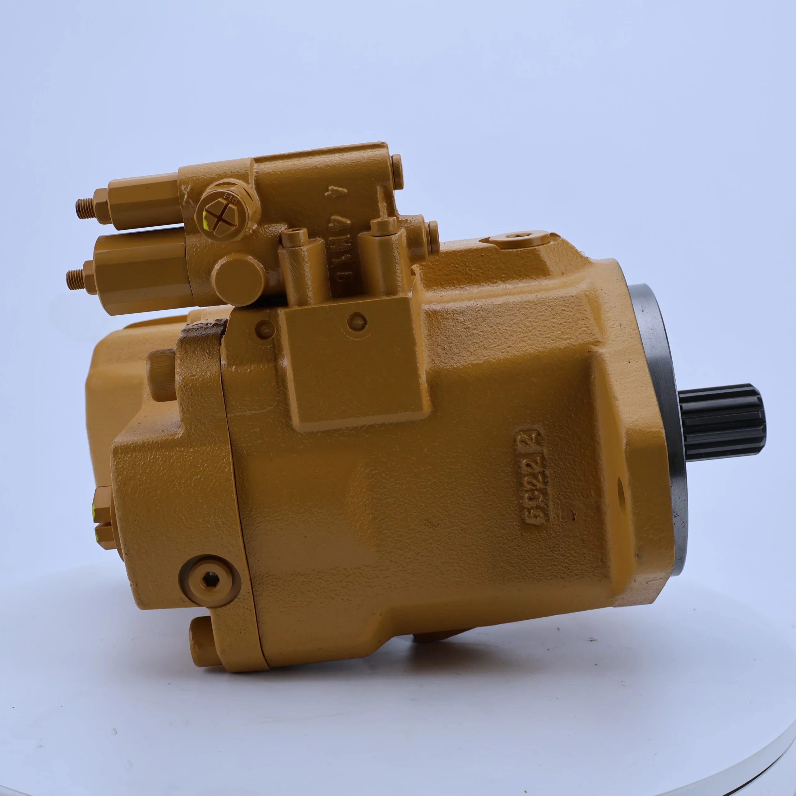


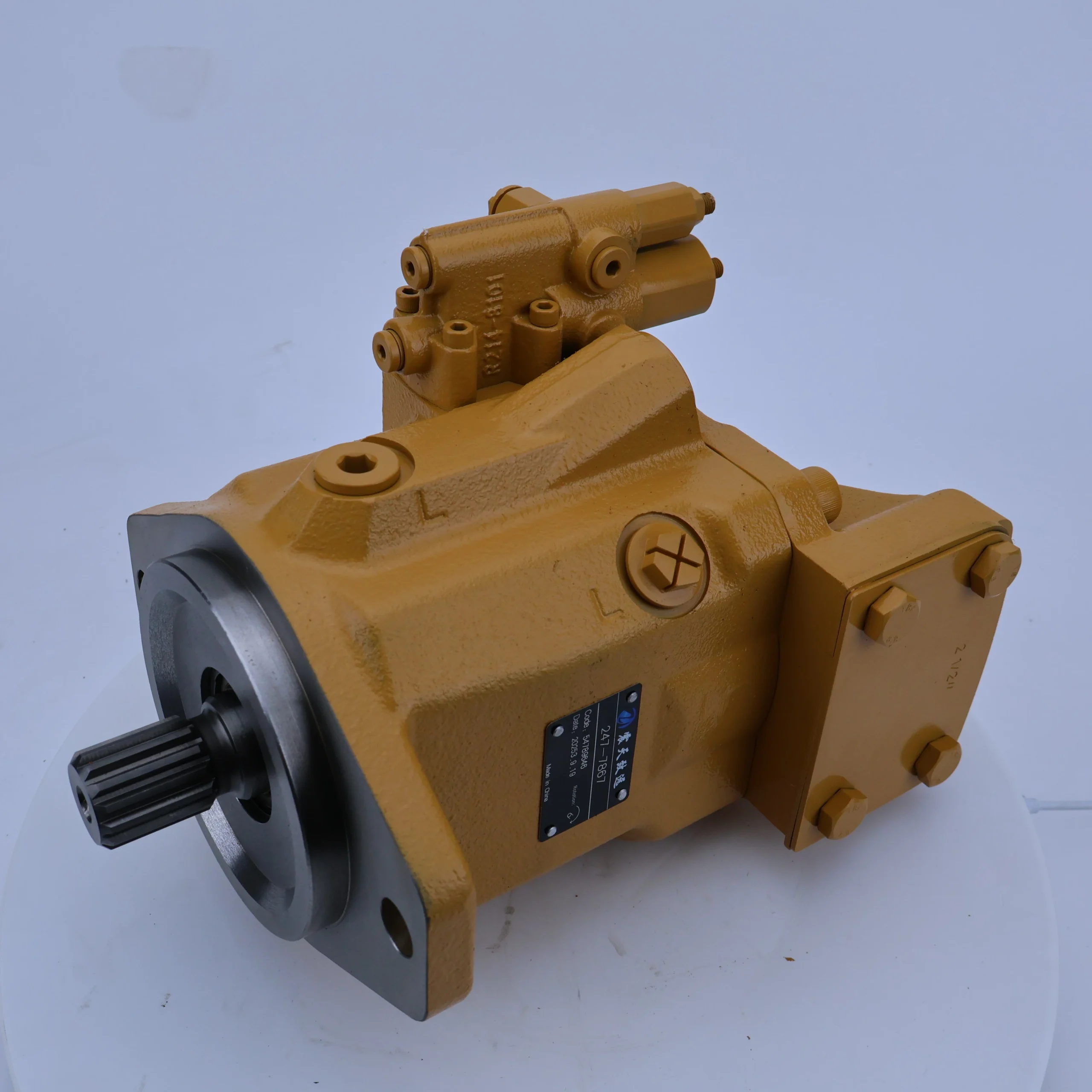
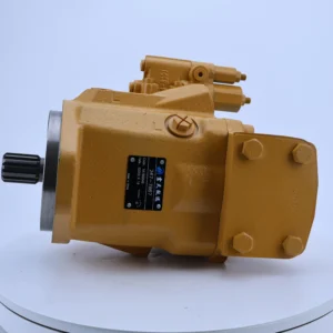

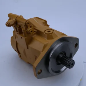
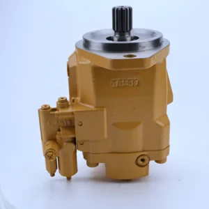

Oem 283-5992 E330c Excavator Cooling Fan Pump Gear Pump GP 201-3786 194-8384 179-9778 247-7867 Hydraulic Pisotn Pump
Core performance parameters
– Pump type: Single-stage external meshing gear oil pump, single pump independent structure, suitable for low-pressure and high-flow hydraulic system power supply, can be used as a single pump or in parallel with multiple pumps.
– Pressure rating: Rated working pressure 16 MPa, short-term peak pressure 20 MPa (lasting ≤3 seconds); The back pressure at the oil return port is allowed to be ≤1.5 MPa, and the pressure fluctuation is ≤±0.5 MPa.
– Flow parameter: Rated displacement 247 mL/r (corresponding to model “247” marking); When the rated speed is 1500 r/min, the rated flow rate is approximately 370 L/min. The speed adaptation range is 800-1500 r/min, and the flow rate is linearly matched with the speed (approximately 200 L/min at 800 r/min).
– Efficiency parameters: Volumetric efficiency ≥85% under rated working conditions, total efficiency ≥80%; At 1500 r/min, the input shaft power should be ≤100 kW, and the power of the matching motor is recommended to be 90-110 kW.
2. Structure and connection parameters
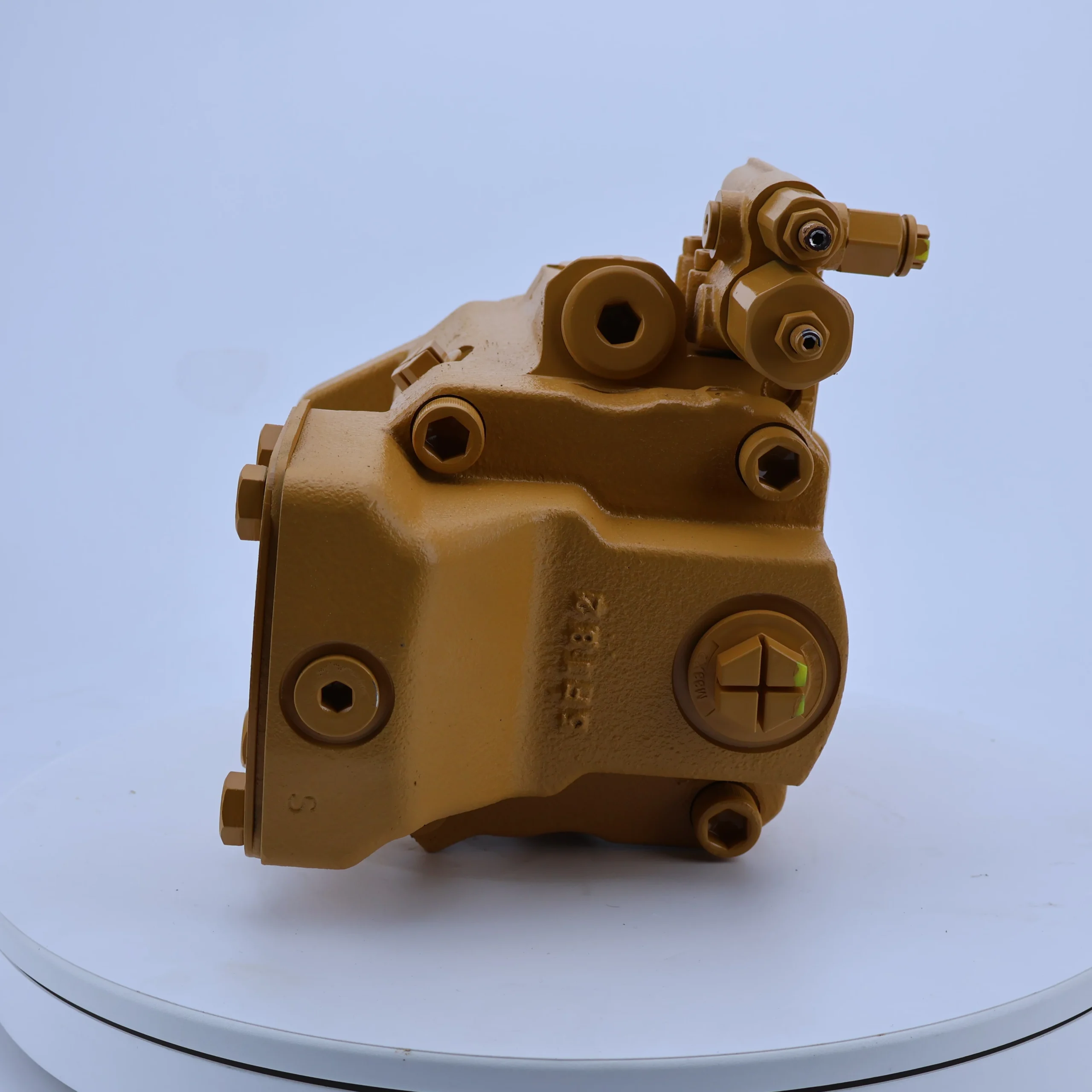
– Structural type: Horizontal installation single pump structure. The gears adopt straight tooth meshing design. The pump body is equipped with an overflow valve (overflow pressure 18 MPa) for overpressure protection, and it integrates large-diameter oil suction and discharge ports.
– Core material: The driving/driven gears are made of alloy structural steel (40CrNiMoA, quenched, hardness HRC52-56); The pump body is made of high-strength gray cast iron (HT300, aged treatment). The sealing parts are made of fluororubber (with a temperature resistance range of -20℃ to 120℃).
– Connection specifications: The diameter of the oil suction port (S port) is Φ 65mm, and the diameter of the oil pressure port (P port) is Φ 50mm. Both are metric threads (M72×2/M60×2). The flange installation complies with the ISO 7005-1 standard, and the input shaft is spline connected (module 4, number of teeth 20).
3. Medium and Environmental requirements
– Medium requirements: It is recommended to use L-HM 46 or L-HM 68 anti-wear hydraulic oil. For low-temperature environments (below -20℃), L-HV 68 hydraulic oil should be selected. The kinematic viscosity of the oil is 20-400 mm²/s, and the moisture content is ≤0.1%.
– Cleanliness standard: The oil cleanliness should reach ISO 4406 17/14 grade. A 60 μm filter should be installed at the front end of the oil suction port, and a 10 μm fine filter is recommended to be installed at the oil pressure port.
– Environmental parameters: Operating environment temperature -20℃ to 80℃, relative humidity ≤95% (no condensation); With a protection grade of IP54, it is suitable for dust and oil contamination working conditions in construction machinery and metallurgical equipment.Ii. Working Principle
This pump is an external gear pump. Its core operates through the mechanism of “gear meshing volume change for oil suction and discharge + built-in overflow valve overpressure protection”. The specific process is as follows:
1. Basic oil suction and discharge process
The motor drives the input shaft to rotate the driving gear, and the driving gear meshes with the driven gear to rotate synchronously in the opposite direction. When the gear tooth grooves change from the meshing state to the separated state, the sealed volume inside the pump cavity increases, creating a local vacuum, and the hydraulic oil is rapidly sucked into the tooth groove space through the large-diameter oil suction port. As the gears continue to rotate, the tooth grooves carry the oil to the oil pressure zone. The gears mesh again, causing the sealed volume to sharply decrease. The oil is squeezed and pressurized, and then stably output from the oil pressure port to the hydraulic system, achieving an efficient conversion of mechanical energy to hydraulic energy.
2. Pressure protection mechanism
The integrated relief valve in the pump body is directly connected to the oil pressure port. When the system working pressure rises to 18 MPa (the set pressure of the relief valve), the valve core of the relief valve opens under the action of pressure, and the excess oil flows back to the oil tank through the relief channel, avoiding damage to the pump body and pipelines due to overpressure. When the system pressure drops below the set value, the relief valve automatically closes to resume normal oil supply and ensure the stability of the system pressure.
Iii. Product Features and Advantages
– High flow supply and abundant power: Rated flow of 370 L/min (1500 r/min), which is 30% higher than that of ordinary gear pumps of the same size. It can independently supply oil to large hydraulic actuators (such as large-diameter hydraulic cylinders and high-speed hydraulic motors) without the need for multiple pumps in parallel, simplifying the system structure.
– High-strength material, wear-resistant and durable: The gears are treated with 40CrNiMoA quenching, featuring high tooth surface hardness and excellent fatigue resistance. The pump body is made of HT300 cast iron and has undergone aging treatment, with a tensile strength of ≥300 MPa. Under rated working conditions, its trouble-free operation life reaches 10,000 hours, making it suitable for heavy-load continuous operation.
– Stable structure and wide adaptability: Mature single-stage external meshing structure, strong universality of components; The wide speed range of 800-1500 r/min can be directly matched with standard motors. By parallling multiple pumps, the flow rate can be expanded to over 1000 L/min, making it suitable for hydraulic systems of different scales.
– Integrated protection, high safety: Built-in relief valve eliminates the cost of installing additional safety valves, and the automatic unloading response time in case of overpressure is ≤0.2 seconds. The large-diameter oil suction port design reduces oil suction resistance, lowers the risk of cavitation, and enhances operational stability.
– Easy maintenance and controllable cost: Modular pump core design, with only gears, seals, etc. as vulnerable parts; When disassembling, there is no need to disassemble the entire pump body. The replacement time of vulnerable parts is ≤2 hours, and the maintenance cost is 40% lower than that of plunger pumps.
Iv. Usage Functions and Purposes
1. Core usage functions
– High-flow oil supply: It provides a continuous and stable low-pressure oil source for large hydraulic actuators. At 1500 r/min, it outputs a flow rate of 370 L/min, which can meet the power requirements of a single actuator with a power of no more than 80 kW.
– Low-pressure power drive: Suitable for actions with low pressure requirements but large flow demands (such as large worktable movement, long-stroke hydraulic cylinder drive), pressure stability ±0.5 MPa.
– Overpressure automatic protection: The built-in relief valve enables 18 MPa overpressure unloading, protecting the pump body and system components. The working pressure (≤16 MPa) can be fine-tuned by adjusting the relief valve knob to meet the requirements of different loads.
– Flow expansion compatibility: Supports parallel operation of multiple pumps, achieving flow superposition through flow distribution valve groups, and is suitable for super-large hydraulic systems (such as metallurgical rolling mills, large injection molding machines).
2. Main application fields
– Construction machinery: lifting and steering systems for loaders over 20 tons, auxiliary action systems for large excavators, and traveling drive systems for crawler cranes.
– Industrial manufacturing equipment: Clamping systems for injection molding machines over 1,000 tons, clamping mechanisms for large die-casting machines, and worktable drive systems for heavy-duty machine tools.
– Metallurgical and mining equipment: roller drive systems for small and medium-sized rolling mills, hydraulic stations for mine crushers, and stirring systems for large flotation machines in mineral processing plants.
– General large-scale equipment: Power sources for large hydraulic lifting platforms, hydraulic systems for luffing mechanisms of port cranes, and hydraulic stations for driving large conveyor belts.
V. Applicable Machines and Scenarios
1. Adapt to the core machine
– Construction machinery: 20-30 ton loaders, excavators over 20 tons, crawler cranes under 50 tons.
– Industrial equipment: 1000-2000 ton injection molding machines, large die-casting machines, heavy-duty horizontal machining centers.
– Heavy industrial equipment: small and medium-sized rolling mills, mine crushers with a diameter of over 1.5 meters, large flotation machines.
– General equipment: Hydraulic lifting platforms over 10 tons, large port cranes, long-distance conveyor belt hydraulic stations.
2. Typical application scenarios
– Loader lifting operation: As the power source of the 20-ton loader lifting system, it outputs 16 MPa pressure oil to drive the lifting hydraulic cylinder, with a flow rate of 370 L/min, ensuring a lifting speed of ≥0.8 m/s. It is suitable for continuous loading and unloading operations, and the pressure remains stable without fluctuation under heavy load.
– Large injection molding machine clamping operation: Supply oil to the clamping system of a 1500-ton injection molding machine. During the clamping stage, the flow rate is fully opened to achieve rapid mold closing (clamping time ≤5 seconds). During the pressure-holding stage, the pressure is stabilized through the relief valve, which is suitable for the batch production scenarios of plastic parts.
Rolling mill roller drive: It provides oil source for the roller drive system of medium and small-sized rolling mills. A single pump drives 8 to 10 groups of roller drives to run synchronously. The speed is controlled by the motor speed regulation. It is suitable for continuous rolling scenarios of strip steel and section steel. The operating noise is ≤80 dB.
Six. Similar models
1. Alternative models of the same series
-200-7867: A small-displacement model of the same structure, with a rated displacement of 200 mL/r (approximately 300 L/min at 1500 r/min), a rated pressure of 16 MPa, the installation dimensions are the same as the original model, suitable for medium-flow scenarios (such as 15-ton loaders), and the cost is 18% lower.
-300-7867: Large-displacement models of the same series, with a rated displacement of 300 mL/r (flow rate approximately 450 L/min at 1500 r/min), a rated pressure of 16 MPa, and the same structural materials. It is suitable for ultra-large flow scenarios (such as 2000-ton injection molding machines), but the cost is 25% higher.
2. Cross-series alternative models
-247-7867-2: Double gear pump model, dual pump integrated design, total displacement 494 mL/r (flow rate approximately 740 L/min at 1500 r/min), rated pressure 16 MPa, suitable for scenarios where dual actuators supply oil simultaneously, with a cost 40% higher.
-247-7868: High-pressure upgraded model, rated pressure 20 MPa, displacement 247 mL/r, gear and pump body materials upgraded, suitable for medium-pressure and high-flow scenarios (such as medium-sized metallurgical equipment), cost 35% higher.
-240-7850: Similar displacement alternative models, rated displacement 240 mL/r, rated pressure 16 MPa, compatible installation dimensions, flow deviation ≤3%, can be used as emergency alternative models, with similar costs.
Vii. Precautions for Use
1. Oil management
– Strictly select L-HM 46 or L-HM 68 anti-wear hydraulic oil. In low-temperature environments (below -20℃), replace it with L-HV 68 hydraulic oil. Oils of different grades must not be mixed. The oil of the new pump must be changed after its first 500 hours of operation, and then every 1,500 hours thereafter.
When the pressure difference of the oil suction filter exceeds 0.2 MPa, the filter element should be replaced immediately. The oil condition should be checked monthly. If the oil is emulsified, discolored or contains metal impurities, the oil tank, pipelines and filter should be thoroughly cleaned and new oil should be replaced.
2. Installation and commissioning
When installing, the coaxiality error between the pump shaft and the motor shaft should be ≤ 0.15mm (for rigid connection) or ≤ 0.3mm (for elastic connection), and the flatness of the flange surface should be ≤ 0.05mm /m to avoid eccentricity causing premature wear of the bearing. The height from the oil suction port to the oil level in the oil tank shall be no more than 0.5m, and the diameter of the oil suction pipeline shall be no less than Φ 65mm, reducing the oil suction resistance.
Before the first start-up, the pump body should be filled with hydraulic oil. Manually turn the gear 3 to 5 times to ensure that the gears rotate smoothly without any jamming. After startup, run it no-load for 10 minutes (at a speed of 1000 r/min). When the oil temperature rises above 30℃, gradually load it. The pressure increase rate should be no more than 1 MPa/ minute.
3. Operation and Maintenance
During operation, real-time monitoring of the pump body temperature (normal ≤75℃, maximum ≤85℃), outlet pressure (≤16 MPa), and operating noise (≤80 dB) is carried out. If a sudden temperature rise of ≥10℃, abnormal pressure fluctuations or abnormal noises are detected, the machine should be immediately shut down, with a focus on checking the cleanliness of the oil, gear wear or the jamming of the relief valve.
Regular maintenance every 2000 hours: Replace the sealing parts and filter elements, and check the wear of the gear tooth surface (replacement is required if the tooth thickness wear is greater than 0.15mm). Disassemble and inspect the internal wear of the pump body every 5,000 hours. If necessary, grind the gears or replace the pump core.
4. Storage protection
When stored for a long time, use a special metal plug to seal the oil suction port and the oil pressure port. Inject anti-rust oil into the pump body (the oil injection volume should be 80% of the pump body volume), and place it in a dry and well-ventilated area (temperature 5-35℃, humidity ≤60%). Manually turn the pump by hand once a month to prevent gear adhesion.
Before putting the pump into use after being idle for more than 8 months, drain the anti-rust oil and flush the pump body with new oil three times. After each flush, run it unloaded for 10 minutes. After installation, gradually load to 50%, 75%, and 100% of the rated pressure. Run each stage for 20 minutes. Only after confirming there is no leakage and the pressure is stable can it be put into use.


