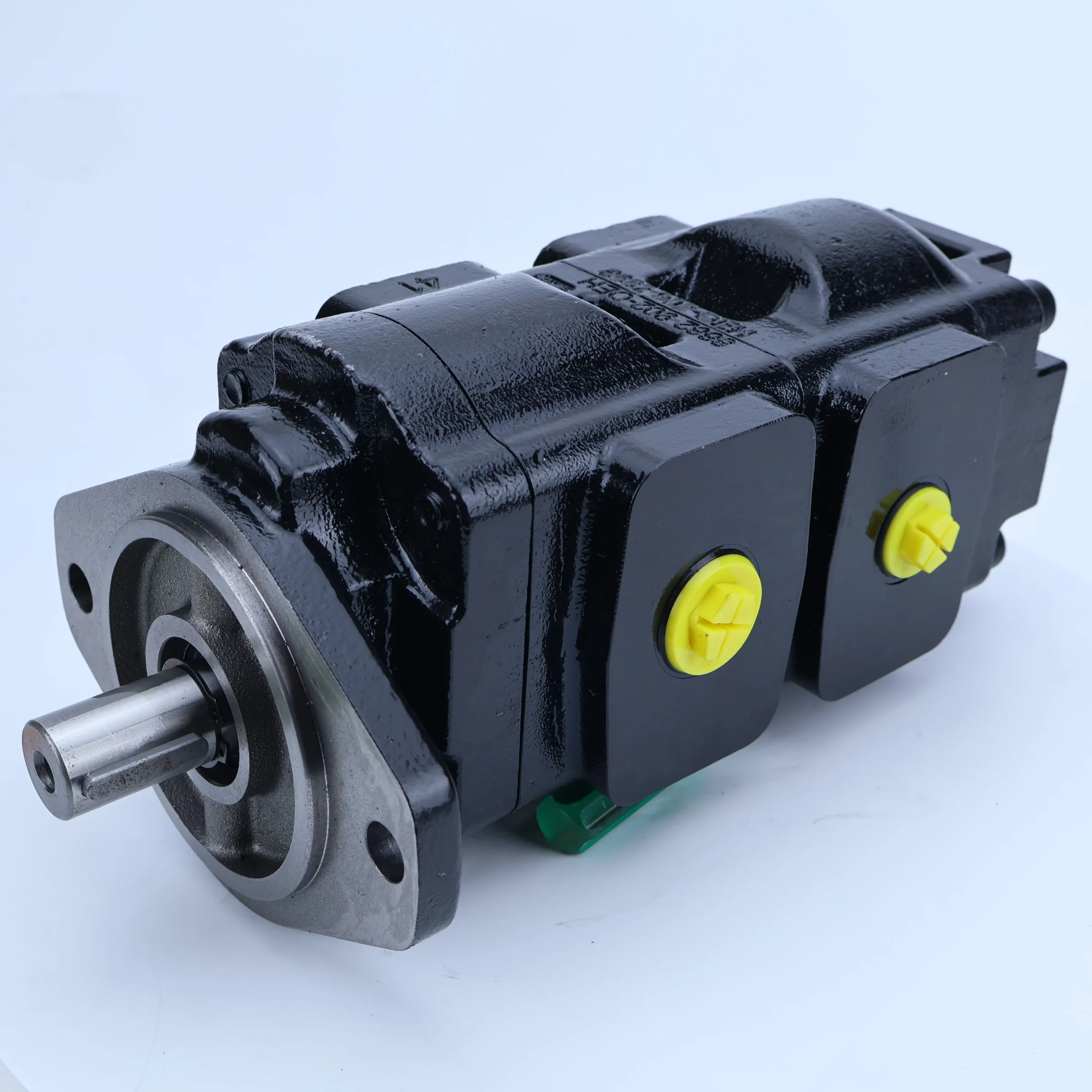


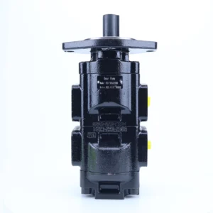
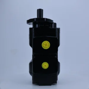


Hydraulic Gear Pump 20/903200 20/912800 20/903100 20/902900 High Pressure Hydraulic Oil Pump for JCB Backhoe Loader 3C 3CX 3DX
Core performance parameters
– Pump type: Single-stage external meshing gear oil pump, single pump independent structure, suitable for low-pressure and medium and small flow hydraulic system power supply, can be used in single or parallel oil supply scenarios.
– Pressure rating: Rated working pressure 16 MPa, short-term peak pressure 20 MPa (lasting ≤3 seconds); The back pressure at the oil return port is allowed to be ≤1.5 MPa, and the pressure fluctuation is ≤±0.5 MPa.
– Flow parameter: Rated displacement 20 mL/r; When the rated speed is 1500 r/min, the rated flow rate is approximately 30 L/min. The speed adaptation range is 800-1500 r/min, and the flow rate is linearly matched with the speed (the flow rate is approximately 16 L/min at 800 r/min).
– Efficiency parameters: Volumetric efficiency ≥85% under rated working conditions, total efficiency ≥80%; At 1500 r/min, the input shaft power should be ≤10 kW, and the power of the matching motor is recommended to be 5.5-11 kW.
2. Structure and connection parameters
– Structural type: Horizontal installation single pump structure. The gears adopt straight tooth meshing design. An overflow valve (overflow pressure 18 MPa) is installed inside the pump body to achieve overpressure protection. The oil suction port and the oil pressure port are integrated.
– Core material: The driving/driven gears are made of alloy structural steel (40Cr, quenched, hardness HRC50-55); The pump body is made of gray cast iron (HT200, aged treatment). The seal is made of nitrile rubber (with a temperature resistance range of -10℃ to 100℃).
– Connection specifications: The diameter of the oil suction port (S port) is Φ 40mm, and the diameter of the oil pressure port (P port) is Φ 32mm. Both are metric threads (M42×2/M36×2). The flange installation is compatible with the standard mounting surface, and the input shaft is connected by a flat key (keyway specification 10×8).
3. Medium and Environmental requirements
– Medium requirements: L-HM 46 anti-wear hydraulic oil is recommended. For low-temperature environments (below -10℃), L-HV 46 hydraulic oil should be selected. The kinematic viscosity of the oil is 20-300 mm²/s, and the moisture content is ≤0.1%.
– Cleanliness standard: The oil cleanliness should reach ISO 4406 18/15 grade, and a 60 μm filter should be installed at the front end of the oil suction port.
– Environmental parameters: Operating environment temperature -10℃ to 70℃, relative humidity ≤95% (no condensation); The protection grade is IP54, suitable for general industrial dust and oil contamination working conditions.Ii. Working Principle
This pump is an external gear pump. Its core operates through the mechanism of “generating volume changes through gear meshing to achieve oil suction and discharge + built-in relief valve protection”. The specific process is as follows:
1. Basic oil suction and discharge process
The motor drives the input shaft to rotate the driving gear, and the driving gear meshes with the driven gear to rotate synchronously in the opposite direction. When the gear tooth grooves change from the meshing state to the separated state, the sealed volume inside the pump cavity increases, creating a local vacuum, and the hydraulic oil is sucked into the tooth groove space through the oil suction port. As the gears continue to rotate, the tooth grooves carry the oil to the oil pressure zone. The gears mesh again, reducing the sealed volume. The oil is squeezed and pressurized, and then stably output from the oil pressure port to the hydraulic system, achieving the conversion of mechanical energy to hydraulic energy.
2. Pressure protection mechanism
The integrated relief valve in the pump body is connected to the oil pressure port. When the system working pressure rises to 18 MPa (the set pressure of the relief valve), the valve core of the relief valve opens under the action of pressure, and the excess oil flows back to the oil tank through the relief channel, preventing the pump body and system components from being damaged due to overpressure. When the system pressure drops below the set value, the relief valve automatically closes to resume normal oil supply and ensure pressure stability.
Iii. Product Features and Advantages
– Single-stage stable structure, strong adaptability: It adopts a mature external meshing structure, with fewer components and high operational stability. The parameter combination of a rated pressure of 16 MPa and a rated flow rate of 30 L/min can be adapted to most low-pressure and medium-flow hydraulic systems without the need for complex adaptation and adjustment.
– Wear-resistant and impact-resistant, with outstanding reliability: The gears undergo 40Cr quenching treatment, resulting in high tooth surface hardness and strong wear resistance. Under the rated working condition of 1500 r/min, the trouble-free operation life can reach 8,000 hours. The pump body is made of HT200 cast iron, which has good impact resistance and can adapt to the vibration conditions of agricultural machinery and construction machinery.
– Easy operation and low maintenance cost: No complex variable mechanism. The flow rate is linearly adjusted with the rotational speed. Different flow rate requirements can be adapted by adjusting the motor speed. The vulnerable parts are only gears, seals, etc. The modular design ensures that the replacement time is no more than 1 hour, and the maintenance cost is 30% lower than that of precision pumps.
– Integrated protection design, high safety: Built-in relief valve eliminates the need to install additional safety valves, simplifying the system pipeline. Precise control of overflow pressure can effectively prevent risks such as pump body burst and pipeline leakage caused by overpressure.
Iv. Usage Functions and Purposes
1. Core usage functions
– Stable oil supply: It provides a continuous and stable low-pressure oil source for hydraulic actuators (hydraulic cylinders, small hydraulic motors). At 1500 r/min, it outputs a flow rate of 30 L/min, which can meet the power requirements of a single actuator with a power of ≤8 kW.
– Low-pressure power drive: Suitable for action scenarios with low pressure requirements (such as clamping, lifting, and conveying), it can supply oil to multiple small actuators simultaneously through pipeline distribution, with pressure stability of ± 0.5MPa.
– Overpressure automatic protection: The built-in relief valve enables 18 MPa overpressure unloading, replacing the traditional external relief valve. This simplifies the system design while ensuring equipment safety, eliminating the need for manual pressure monitoring.
2. Main application fields
– Agricultural machinery: Suspension and lifting systems for 80-120 horsepower tractors, header adjustment and conveying systems for combine harvesters, and drive systems for ear picking mechanisms of corn harvesters.
– Light industrial machinery: clamping and ejection systems for small injection molding machines under 50 tons, pressing mechanisms for fully automatic strapping machines, and paper feeding drive systems for small printing machines.
– Construction machinery: Lifting systems for 1-3 ton small loaders, steering assistance systems for 3-5 ton forklifts, and vibration regulation systems for small road rollers.
– General equipment: Power sources for small and medium-sized hydraulic stations, oil supply for equipment lubrication systems, and circulating oil pumps for cooling systems.
V. Applicable Machines and Scenarios
1. Adapt to the core machine
– Agricultural machinery: Wheeled tractors with over 80 horsepower, self-propelled combine harvesters, medium-sized corn harvesters.
– Light industry machinery: 30-50 ton small injection molding machines, fully automatic carton strapping machines, small gravure printing machines.
– Construction machinery: 1-3 ton small loaders, 3-5 ton internal combustion forklifts, small hand-guided rollers.
– General equipment: Small hydraulic test bench, machine tool lubrication station, industrial cooling circulation system.
2. Typical application scenarios
– Tractor suspension operation: As the power source of the tractor suspension system, it outputs 16 MPa pressure oil to drive the suspension mechanism to rise and fall. The flow rate is adjusted according to the rotational speed to meet the cultivation requirements of different crop heights, and the continuous operation stability in the field is high.
– Strapping machine compression operation: Provide oil source for the compression mechanism of the strapping machine, with a stable pressure of 12-14 MPa. Control the compression speed through flow regulation to meet the packaging density requirements of different materials such as cartons and plastic bottles, and operate without failure in a single shift.
– Small hydraulic station oil supply: As the core power source for medium and small-sized hydraulic stations, it provides oil for 2-3 small hydraulic cylinders, achieving coordinated actions such as part clamping and positioning. The pressure control accuracy meets general processing requirements (± 0.5MPa).
Six. Similar models
1. Alternative models of the same series
-15/903200: A small-displacement model of the same structure, with a rated displacement of 15 mL/r (approximately 22.5 L/min at 1500 r/min), a rated pressure of 16 MPa, and the installation dimensions are the same as the original model. It is suitable for low-flow scenarios (such as small lubrication systems), and the cost is 15% lower.
-25/903200: A large-displacement model of the same series, with a rated displacement of 25 mL/r (flow rate approximately 37.5 L/min at 1500 r/min), a rated pressure of 16 MPa, and the same structural materials. It is suitable for high-flow scenarios (such as large tractors), but the cost is 20% higher.
2. Cross-series alternative models
-20/903200-2: Dual gear pump model, dual pump integrated design, total displacement 40 mL/r (flow rate approximately 60 L/min at 1500 r/min), rated pressure 16 MPa, suitable for scenarios where dual actuators supply oil simultaneously (such as lifting and steering of loaders), with a cost 40% higher.
-20/903200-H: High-pressure upgraded model, rated pressure 20 MPa, displacement 20 mL/r, gear and pump body materials upgraded, suitable for medium-pressure scenarios (such as auxiliary systems for medium-sized hydraulic presses), cost 30% higher.
-18/903100: Similar displacement alternative model, rated displacement 18 mL/r, rated pressure 16 MPa, compatible installation dimensions, flow deviation ≤10%, can be used as an emergency alternative model, with similar cost.
Vii. Precautions for Use
1. Oil management
Strictly select L-HM 46 anti-wear hydraulic oil. In low-temperature environments (below -10℃), replace it with L-HV 46 hydraulic oil. Different grades of oil must not be mixed. The oil of the new pump must be changed after its first 500 hours of operation, and then every 1,500 hours thereafter.
When the pressure difference of the oil suction filter exceeds 0.2 MPa, the filter element should be replaced immediately. The oil condition should be checked monthly. If the oil is emulsified, discolored or contains metal impurities, the oil tank and pipelines should be thoroughly cleaned and new oil should be replaced.
2. Installation and commissioning
When installing, the coaxiality error between the pump shaft and the motor shaft should be no more than 0.2mm (for rigid connection) or no more than 0.3mm (for elastic connection) to avoid bearing wear due to eccentricity. The height from the oil suction port to the oil level in the oil tank shall be no more than 0.5m, and the diameter of the oil suction pipeline shall be no less than Φ 40mm to reduce the oil suction resistance and prevent cavitation.
Before the first start-up, the pump body should be filled with hydraulic oil. Manually turn the gear 3 to 5 times to ensure that the gears rotate smoothly without any jamming. After startup, run no-load for 5 minutes. Wait until the oil temperature rises above 30℃ before gradually loading. The pressure increase rate should be no more than 1 MPa/ minute.
3. Operation and Maintenance
During operation, real-time monitoring of the pump body temperature (normal ≤75℃, maximum ≤85℃), outlet pressure (≤16 MPa), and operating noise (≤75 dB) is conducted. If a sudden temperature rise, abnormal pressure, or unusual noise is detected, the machine should be immediately shut down, with a focus on checking for oil cleanliness, gear wear, or relief valve jamming.
Regular maintenance every 2000 hours: Replace the sealing parts and filter elements, and check the wear of the gear tooth surface (replacement is required if the tooth thickness wear is greater than 0.1mm). Disassemble and inspect the internal wear of the pump body every 4,000 hours. If necessary, grind the gears or replace the pump body.
4. Storage protection
When stored for a long time, seal the oil suction port and the oil pressure port with plugs, inject anti-rust oil into the pump body (the oil volume should be 80% of the pump body volume), and place it in a dry and well-ventilated area (temperature 5-35℃, humidity ≤60%). Manually turn the pump by hand once a month to prevent gear adhesion.
Before putting the pump into use after being idle for more than six months, drain the anti-rust oil, flush the pump body twice with new oil, run it no-load for 10 minutes, and then gradually load it. Only after confirming there is no leakage and the pressure is stable can it be put into use.


