
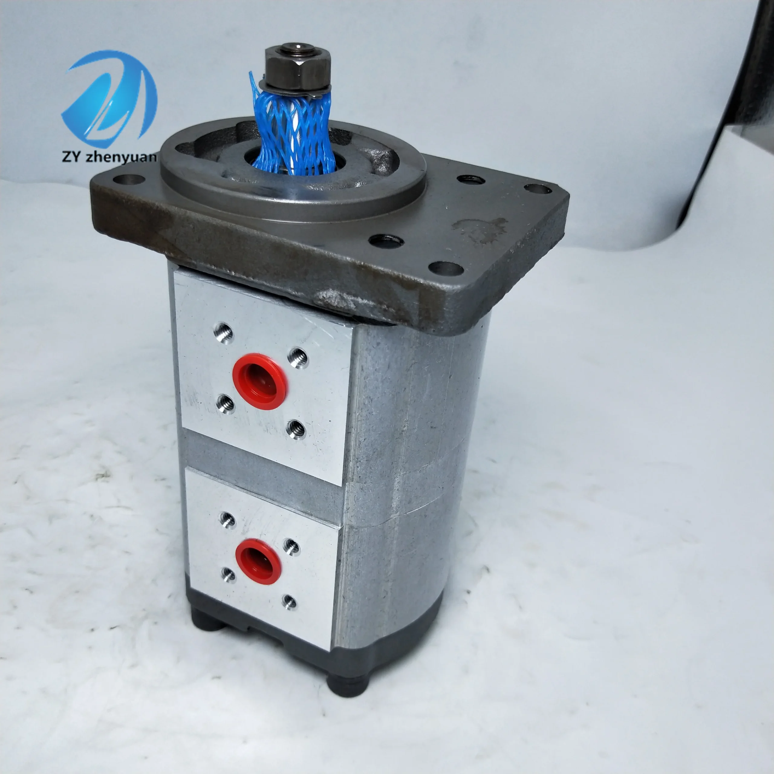
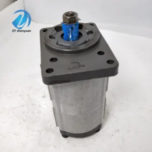

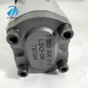


SNM2NL/022BN06BAL6E4ESPRYA/NNNAN08FEB18 Hydraulic Gear Pump SNM SNM2 SNM2NN SNM2NL SNU SNP SKP High Pressure Oil Pump
Basic performance parameters
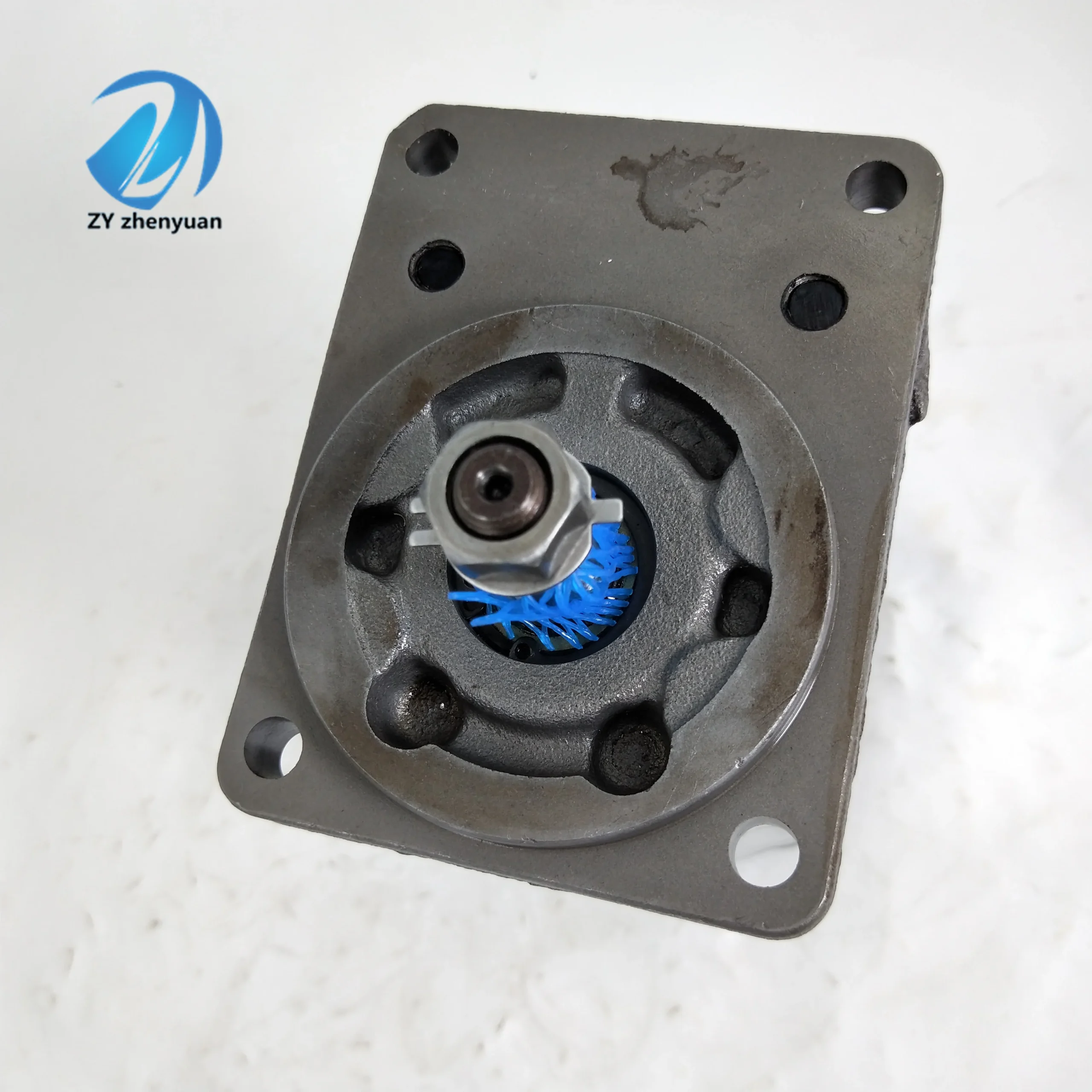
Pump body type: External gear pump, single-stage quantitative structure, integrated one-piece relief valve
Rated displacement: 22 cc/rev (The “022” in the model corresponds to the displacement specification)
Pressure parameters: Rated working pressure 210 bar, maximum allowable pressure 250 bar (short-term ≤10 seconds), return oil back pressure ≤2 bar
Speed range: Rated speed 2800 rpm, maximum speed 4000 rpm, minimum stable speed 600 rpm
Efficiency indicators: Rated working condition volumetric efficiency ≥93%, total efficiency ≥88%, pressure loss ≤5 bar (at rated flow)
Flow output: The output flow at the rated speed is approximately 61.6 L/min (22 cc/rev×2800 rpm÷1000)
Structure and connection parameters
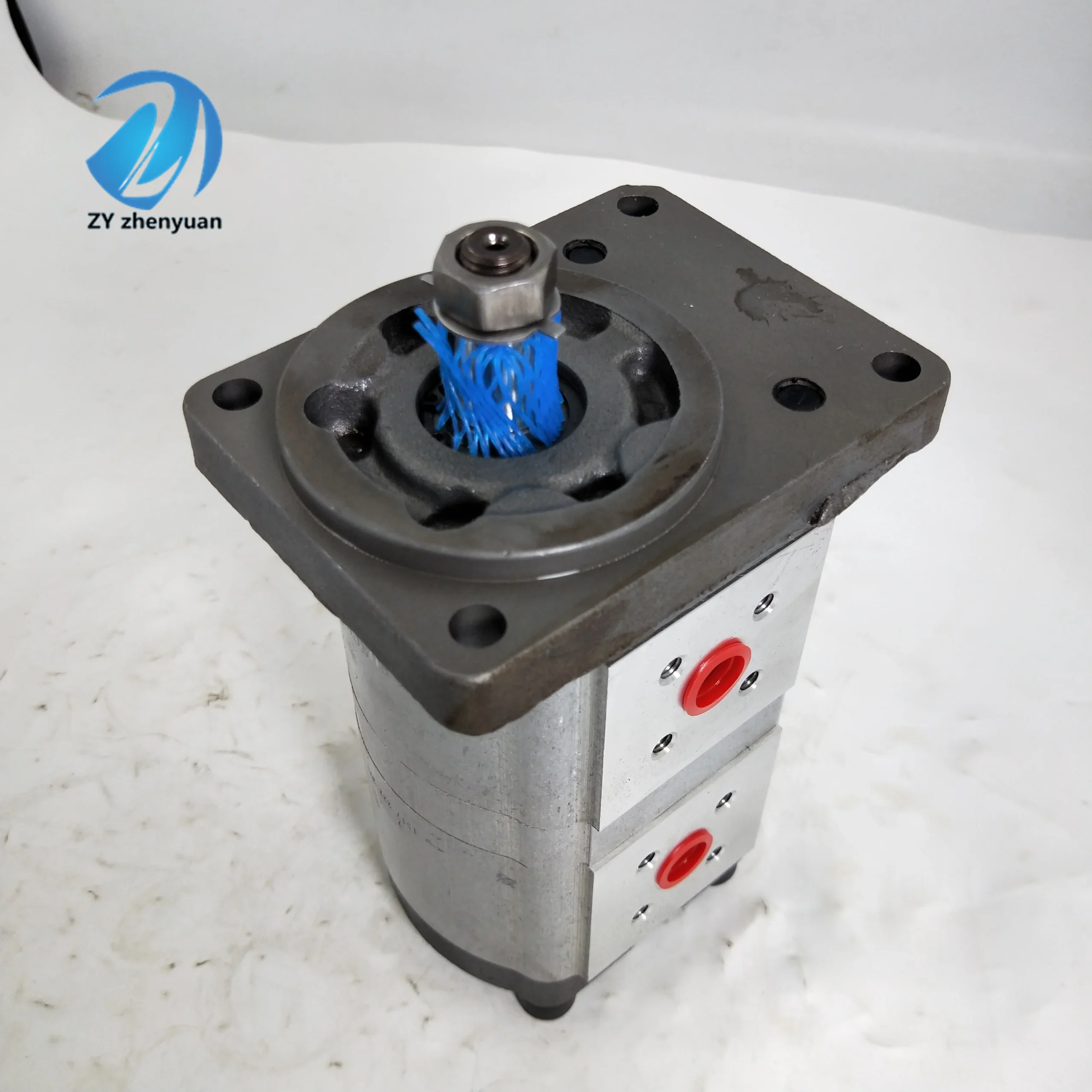
Structural type: Cast iron integral pump body, nitrided alloy steel gears, pressure self-compensating distribution plate, double-end mechanical seal
Installation specification: Flange installation (compatible with ISO 3019-1 standard), and the model number “BN06” corresponds to the installation size of NG06
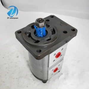
Connection specifications: The oil port thread is G3/4 (suction port, outlet port), and the control oil port is G1/8. The output shaft is connected by a flat key (specification: 12×30)
Dimensions: Length × width × height ≈260×190×175 mm, weight approximately 12 kg
Protection grade: IP65, suitable for dusty and humid industrial environments
Medium and environmental requirements
Compatible medium: L-HM 32/46/68 anti-wear hydraulic oil, allowable medium viscosity range 10-400 mm²/s, moisture content ≤0.02%
Environmental parameters: Operating temperature -25 ℃ to 90℃, relative humidity ≤95%; The cleanliness of the oil should reach ISO 4406 14/11 grade
Filtration requirements: A filter screen of ≥80 mesh should be installed on the oil suction side, and the filtration accuracy on the oil return side should be ≤25 μmIi. Working Principle
This gear pump is an external meshing quantitative gear pump. Its core converts hydraulic energy into mechanical energy through the “change in gear meshing volume”. The specific process is as follows:
Oil absorption process: The motor drives the driving gear to rotate, which in turn engages and rotates the driven gear in the opposite direction. A local vacuum is formed on the side where the two gears disengage from meshing. Under the action of atmospheric pressure, the hydraulic oil enters the pump chamber through the oil suction port and fills the gap between the gear tooth grooves.
Oil transfer process: The gears keep rotating, and the hydraulic oil in the tooth grooves is carried to the meshing side as the gears rotate. As the gears gradually mesh, the volume of the tooth grooves continuously decreases, and the oil is mechanically squeezed to generate pressure.
Oil discharge process: The high-pressure oil under pressure is guided to the oil outlet through the distribution plate and discharged, entering the hydraulic system to drive the actuating elements. The distribution plate is designed with pressure self-compensation to ensure a tight fit between the gear end face and the distribution plate, reducing internal leakage.
Protection mechanism: Built-in integrated relief valve. When the system pressure exceeds the maximum allowable value of 250 bar, the relief valve will automatically open to guide the excess oil back to the suction chamber, preventing the pump body and pipelines from being overloaded and damaged.
Iii. Product Features and Advantages
Core features
Low-noise design: By adopting an optimized tooth profile curve and high-precision gear meshing clearance (≤ 0.03mm), the operating noise is reduced by 8-10dB compared to conventional gear pumps, making it suitable for cab equipment and indoor operation scenarios
High wear-resistant structure: The gears undergo nitriding treatment (hardness HRC62-65), the inner wall of the pump body is precisely honed, and combined with a pressure self-compensating distribution plate, it has excellent wear resistance
Multi-outlet expansion capability: Supports integrated manifold blocks, providing up to 3 independent output ports. Each port can independently control flow and pressure, making it suitable for complex hydraulic systems
Wide operating condition adaptability: With a wide temperature range of -25℃ to 90℃ and a high-pressure tolerance of 250 bar, it can adapt to harsh working conditions such as high and low temperatures and heavy load fluctuations
Outstanding advantages
Strong reliability: The cast iron pump body has good impact resistance, and the mechanical seal has excellent anti-leakage effect. The continuous operation life is ≥ 12,000 hours
Flexible installation: Compatible with both flange and foot mounting methods, the oil port position can be adjusted as needed to adapt to different equipment layouts
Easy maintenance: Modular design, gears, seals and other vulnerable parts can be replaced separately. The relief valve can be adjusted without disassembling the pump body and can be calibrated online
Energy-saving and highly efficient: The optimized flow channel design reduces pressure loss, and the high volumetric efficiency minimizes energy loss, resulting in lower long-term operating costs
Iv. Usage Functions and Purposes
Core usage functions
Quantitative oil delivery: It continuously supplies stable flow and pressure of hydraulic oil to the hydraulic system as the power source of the system
Pressure stability: The built-in relief valve limits the maximum pressure of the system to prevent overload and ensure the safety of hydraulic components
Multi-loop fuel supply: It works in conjunction with the manifold block to achieve independent fuel supply at multiple outlets, controlling the synchronous or sequential operation of multiple actuating elements
Medium transportation: Transport hydraulic oil free of solid particles and with lubricity to achieve power transmission and energy conversion
Main uses
As a core power component of the hydraulic system, it connects the power source (motor) with the actuator (cylinder, motor), converts mechanical energy into hydraulic energy, and provides power for the hydraulic actuator of various machinery. It is a key component of the hydraulic transmission system.
V. Applicable Machines and Scenarios
Construction machinery: excavators, loaders, telescopic boom forklifts, rollers; It is suitable for heavy-duty scenarios such as hydraulic arm extension and retraction, bucket flipping, and walking drive, and can withstand high pressure and harsh outdoor environments
Agricultural machinery: tractors, combine harvesters, seeders; Control the lifting of agricultural machinery and the drive of harvesting devices to adapt to the high and low temperatures and dusty working conditions in the field
Industrial machinery: injection molding machines, presses, CNC machine tools, packaging machinery; It is suitable for high-frequency and stable action scenarios such as mold opening and closing, slider drive, and feeding mechanism
Special machinery: aerial work platforms, material handling equipment, ship deck machinery (winches, servos); It meets the requirements of precise positioning and stable operation, and is compatible with various indoor and outdoor environments
Other scenarios: Hydraulic test benches, hydraulic systems for automated production lines, and hydraulic auxiliary systems for electric/hybrid power equipment
Six. Similar models
Different models of the same series displacement
SNM2NL / 016 bn06bal6e4esprya/NNNAN08FEB18:16 cc/rev rated capacity, rated flow of 44.8 L/min, the adaptation of small hydraulic system (e.g., small machine, mini loader), more compact volume
SNM2NL / 028 bn06bal6e4esprya/NNNAN08FEB18:28 cc/rev rated capacity, rated flow of 78.4 L/min, the maximum pressure of 250 bar, adaptation of large equipment (such as 5 tons loaders, shield machine auxiliary system)
Models with the same displacement but different functions
SNM2NL / 022 bn06bal6e4mmrya/NNNAN08FEB18: manual regulation overflow valve type, simple adaptation pressure fixed hydraulic system, the cost is lower
SNM2NL / 022 bn06bal6e4ecrya/NNNAN08FEB18: electro-hydraulic proportional control model, support remote to adjust the output pressure and flow, adaptive automated production line, the control precision is higher
SNM2NL / 022 cn06bal6e4esprya/NNNAN08FEB18: foot pedestal installation types, and the installation method is more flexible and adaptive equipment without flange installation space, other performance in line with the original model
Vii. Precautions for Use
Installation and commissioning
When installing, ensure that the coaxiality error between the pump shaft and the motor shaft is ≤ 0.1mm. Use an elastic coupling for connection to avoid radial/axial force acting on the pump shaft
Prioritize installation close to the fuel tank. The length of the oil suction pipeline should be no more than 2 meters and the diameter no less than 25 mm to reduce oil suction resistance. The pipeline connection must be tightly sealed to prevent air leakage and insufficient oil absorption
Before the first start-up, hydraulic oil should be injected into the pump cavity, and the pump should be manually turned by hand for 3 to 5 turns to ensure there is no jamming. When starting up, first open the oil suction valve, and run it no-load at low pressure (50 bar) and low speed (1000 rpm) for 30 minutes, gradually increasing it to the rated parameters
For outdoor installation, proper protection of the pump body is necessary to avoid direct sunlight and rain. Reserve a heat dissipation space of ≥ 200mm around and keep it away from high-temperature heat sources
Medium and Operation Management
Strictly use the designated type of anti-wear hydraulic oil. It is strictly prohibited to mix different grades of oil or use oil containing impurities or with high moisture content. Test the quality of the oil every six months. Replace it in time when the contamination exceeds the standard
During operation, monitor the pump body temperature (normal ≤85℃, maximum not exceeding 95℃), pressure and noise. If there is a sudden increase in temperature, excessive pressure fluctuation or abnormal noise, stop the machine immediately for inspection
Do not run without oil (idling for more than 5 seconds may cause damage to gears and bearings). Do not operate at the maximum speed for a long time (single time ≤15 minutes).
After the system has been shut down for a long time (more than 7 days), the air in the pipeline must be completely drained before restarting. Run it at low speed without load for 15 minutes before reloading
Maintenance and upkeep
Regular maintenance cycle: Replace the hydraulic oil and filter element every 5,000 hours. Disassemble and inspect the gear wear every 10,000 hours (replace when the tooth surface wear is ≥ 0.1mm), and replace the mechanical seal and bearing
Daily maintenance requires cleaning the heat dissipation channels on the surface of the pump body and checking the sealing of the pipe joints. The relief valve should be calibrated with a pressure gauge for adjustment. It is strictly forbidden to exceed the maximum allowable pressure
When stored for a long time, all oil ports should be sealed with special plugs, anti-rust oil should be injected into the pump cavity, and lithium-based grease should be applied to the output shaft. Store in a dry and well-ventilated environment at 0-45℃. Manually turn the wheel once every three months
Before being put into use after being idle for more than 12 months, the pump cavity and pipelines must be thoroughly cleaned, the sealing parts and hydraulic oil replaced, and the pressure of the relief valve recalibrated. Only after the trial operation is normal can it be put into use


