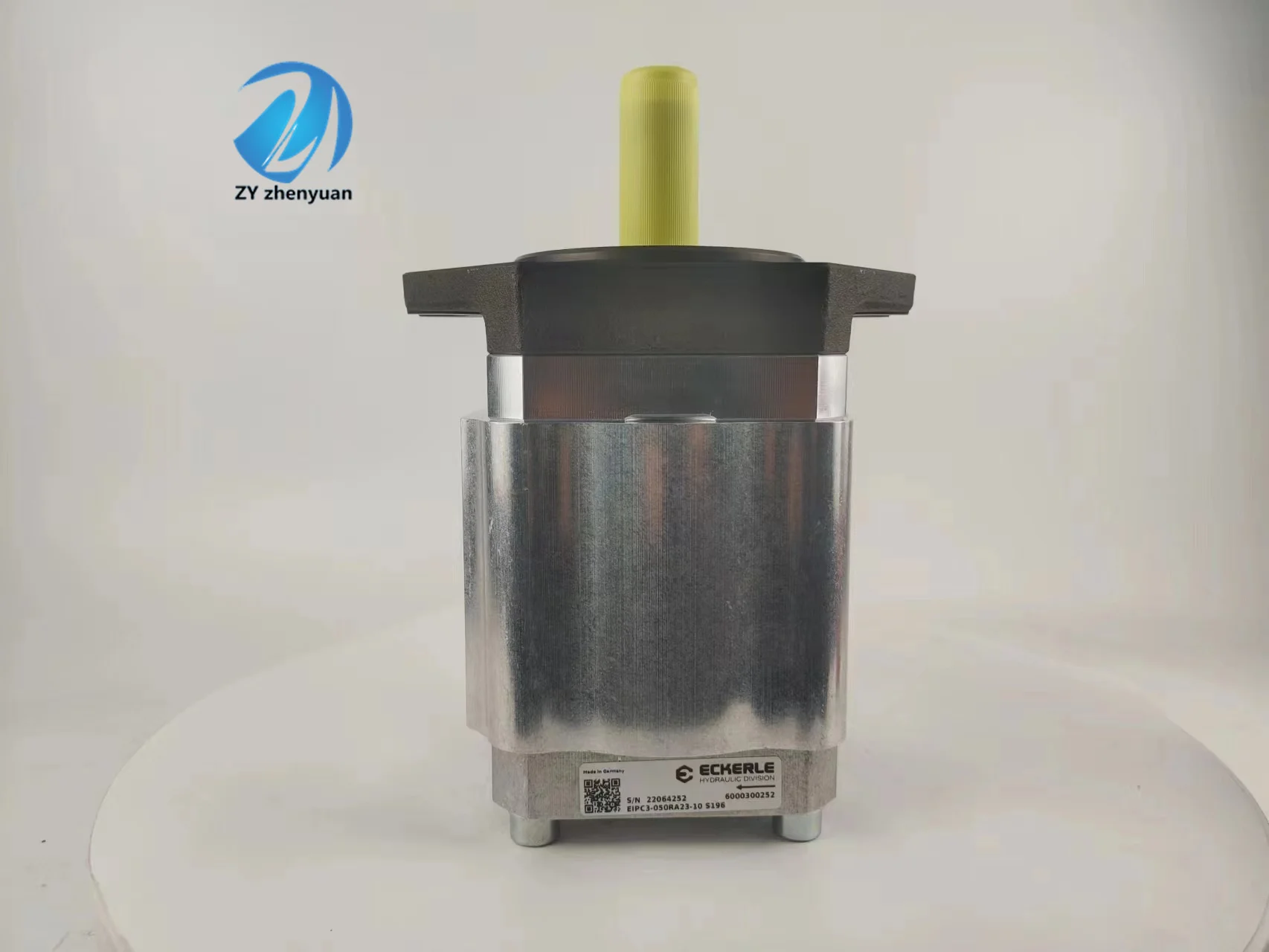

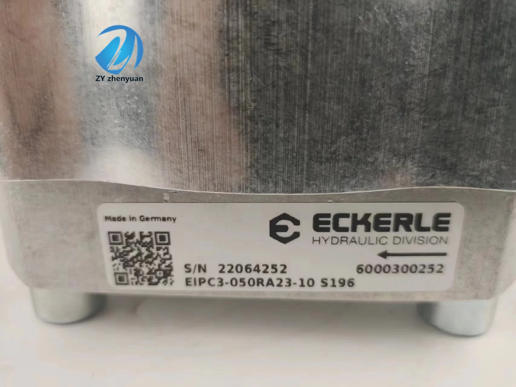

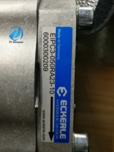
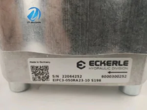
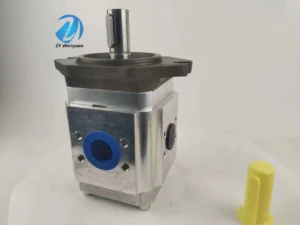
Hydraulic EIPC3-050RA23-10 Internal Gear Pump EIPH EIPC2 EIPC3 EIPC5 EIPC6 High Pressure Oil Pump for Injection Molding Machine
Core performance parameters
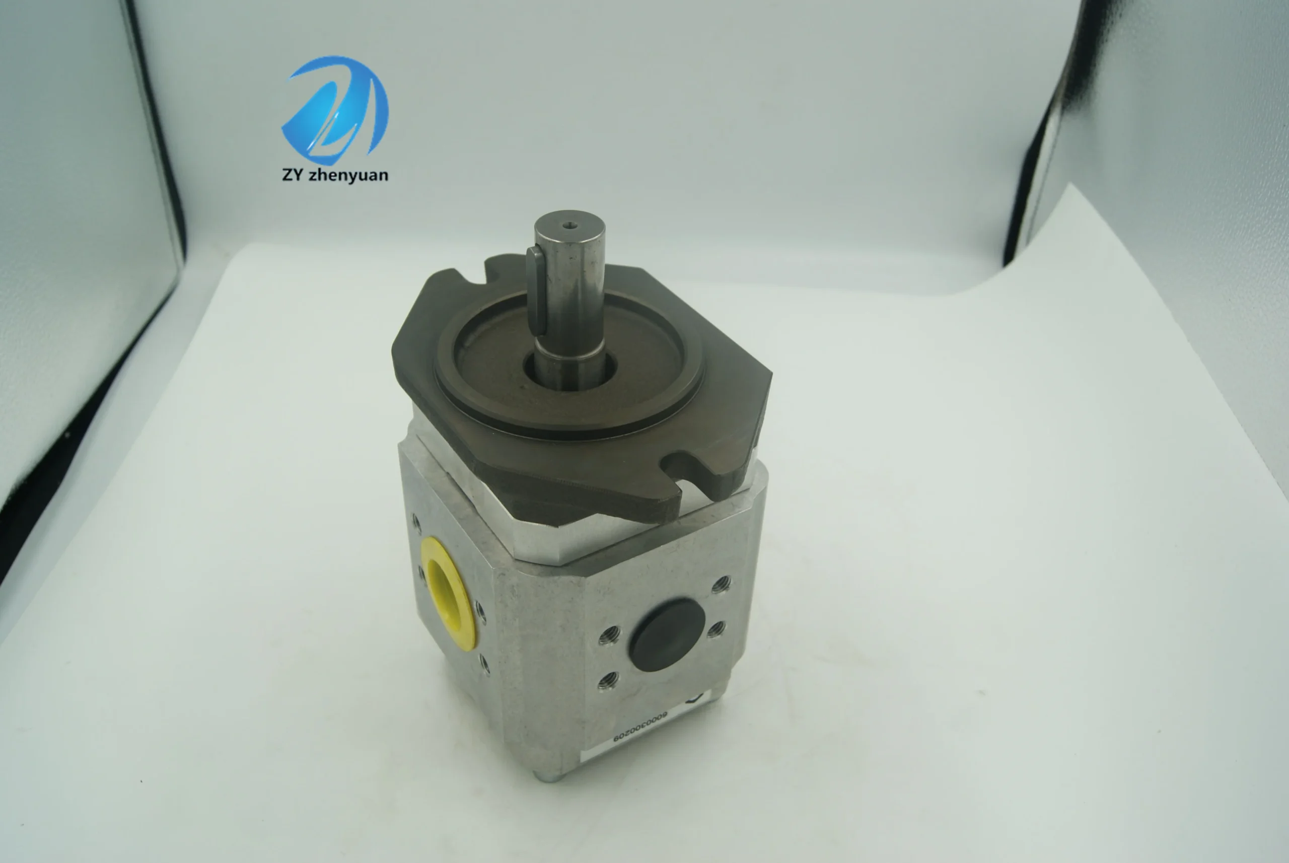
– Pump type: External meshing gear fixed displacement pump, right-rotating steering, open circuit design, suitable for medium and low pressure hydraulic systems, providing a stable fixed displacement hydraulic source for small and medium-sized actuators.
– Displacement and pressure parameters: Rated displacement 50 mL/r; Rated working pressure: 20 MPa, maximum allowable pressure: 25 MPa (short-term ≤10 seconds); The rated speed is 1500 r/min, the maximum speed is 2000 r/min (short-term ≤5 minutes), and the minimum stable speed is 300 r/min.
– Flow rate and efficiency parameters: Rated flow rate of 75 L/min at rated speed; Volumetric efficiency ≥88%, total efficiency ≥82%; The imported vacuum degree is ≤0.04 MPa (at rated speed).
– Operating characteristics: Continuous operating oil temperature ≤80℃, rated working condition noise value ≤88 dB (measured at 1 meter); The fault-free operating life under rated conditions is ≥ 8,000 hours.
2. Structure and connection parameters
– Structural type: External meshing involute gear structure, integrated alloy cast iron pump body, alloy steel gear pair, needle roller bearing and combined sealing assembly; It adopts a precise control design of gear clearance and is equipped with a pressure balance groove to reduce radial force.
– Core material: The driving/driven gears are made of chromium-molybdenum alloy steel (quenched and tempered, hardness HRC58-62); The pump body is made of alloy cast iron QT450-10 (hardness HB200-230). The bearing is a high-load needle roller bearing (material GCr15). The seal is a combination of oil-resistant nitrile rubber and polytetrafluoroethylene (with a temperature resistance of ≤100℃).
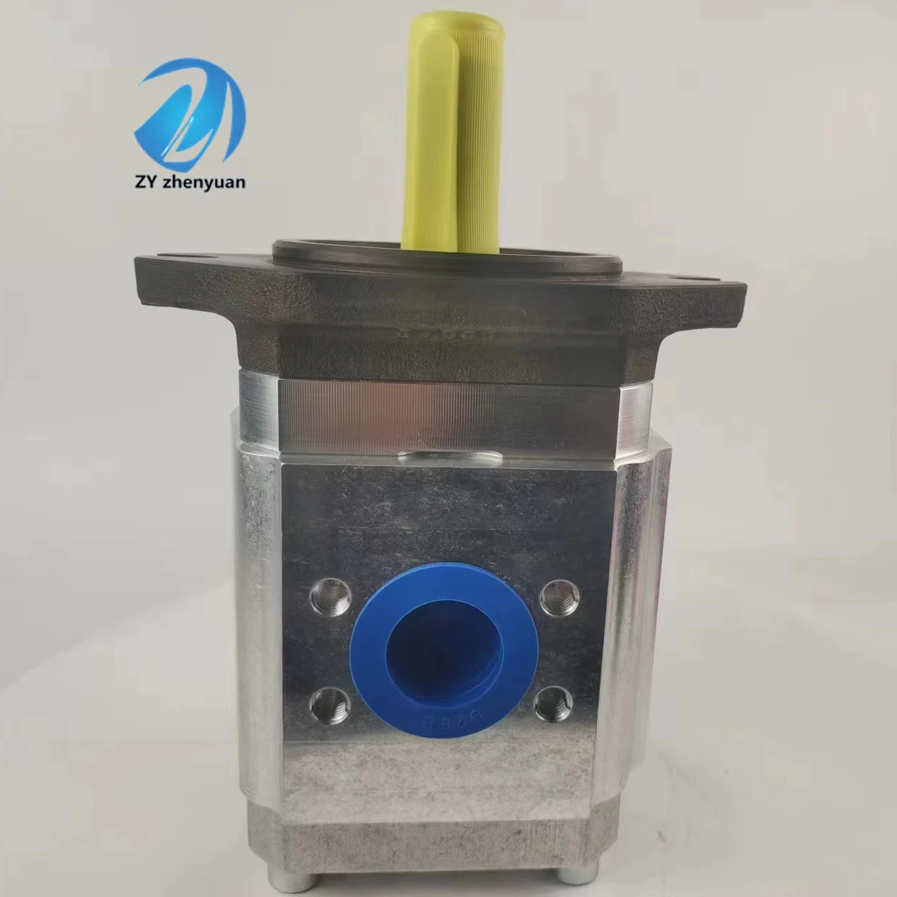
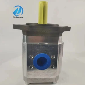
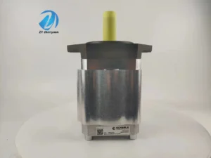
– Connection specifications: The oil suction port (P) is of G1″ thread, and the oil discharge port (A) is of G3/4″ thread. The drive shaft is connected by a flat key (specification: 14×35). The installation method is flange installation (bolt center distance 120× 80mm). The weight of the pump body is approximately 18 kg, and its external dimensions (length × width × height) ≈320×200×160 mm.
3. Medium and Environmental requirements
– Medium requirements: L-HM 46 anti-wear hydraulic oil is suitable for normal temperature. L-HM 32 is selected for low-temperature environment (below -15℃). The allowable medium viscosity is 10-300 mm²/s, with a moisture content of no more than 0.03%. Solid particles (particle size > 15 μm) are strictly prohibited.
– Cleanliness standard: The oil cleanliness should reach ISO 4406 16/13 grade. A 15 μm filter should be placed in front of the oil suction port. The filter should be replaced when the pressure difference of the filter is greater than 0.1 MPa.
– Environmental parameters: Operating environment temperature -20℃ to 85℃, relative humidity ≤95% (short-term condensation is allowed); With a protection grade of IP65, it is suitable for small and medium-sized construction machinery, industrial hydraulic equipment, agricultural machinery and other scenarios.Ii. Working Principle
This pump is an external meshing gear quantitative pump. Its core converts mechanical energy into hydraulic energy through the mechanism of “gear meshing volume change – negative pressure oil suction – high-pressure oil discharge”. The specific process is as follows:
1. Core process of oil suction and discharge
The drive shaft rotates the driving gear, and the driving gear and the driven gear mesh with each other and rotate in opposite directions. When the two gears separate from the meshing tooth surfaces in the oil suction area (on the left side of the pump body), a closed chamber with an increased volume is formed between the gear teeth. The pressure inside the chamber drops, creating a negative pressure. The hydraulic oil is then sucked into the space between the teeth through the oil suction port and the filter. As the gears rotate, the oil between the teeth is carried to the oil discharge area (on the right side of the pump body). At this time, the meshing tooth surfaces of the two gears squeeze each other, the volume between the teeth decreases, and the oil is squeezed into high-pressure oil, which is then conveyed to the hydraulic system through the oil discharge port to complete the quantitative oil supply.
2. Pressure balance and sealing mechanism
The pump body is equipped with a pressure balancing groove, which leads part of the high-pressure oil from the oil discharge area to the end of the gear bearing, balancing the radial pressure of the gear and reducing the wear of the bearing. Precision clearance seals (clearance ≤ 0.03mm) are adopted between the gears and the pump body and end cover, and combined with the sealing parts to prevent oil leakage, ensuring that the volumetric efficiency remains stable at over 88%. When the system pressure exceeds the rated value, the matching relief valve automatically unloads to protect the pump body from overpressure damage.
Iii. Product Features and Advantages
– Simple structure and high reliability: The external meshing gear structure has no complex variable mechanism, and the number of components is reduced by 60% compared with the plunger pump. The gears and bearings are made of wear-resistant materials, with no vulnerable precision components. The failure rate is 50% lower than that of axial piston pumps, making it suitable for frequent start-stop scenarios.
– Excellent anti-pollution ability: The gear pair clearance is larger than that of precision pumps. The oil cleanliness requirement is only ISO 4406 16/13 grade, and it can withstand slight impurity contamination. A 15 μm filter at the oil suction port can meet the requirements, reducing maintenance costs by 40% compared to servo pumps. It is suitable for dusty agricultural and construction machinery scenarios.
– Stable and controllable quantitative oil supply: The fixed displacement design ensures that the output flow fluctuation is ≤3%, providing higher quantitative accuracy compared to variable pumps. At the rated speed, the flow rate remains stable at 75 L/min, eliminating the need for additional flow regulation components. This simplifies the system pipeline design and is suitable for single-actuator uniform operation scenarios.
– Convenient and economical installation and maintenance: The flange installation complies with general standards and can directly replace products of the same specification but different brands. It weighs only 18 kilograms and can be moved and installed by a single person. The vulnerable parts (gears, seals) have strong versatility, low replacement costs, and the operation and maintenance costs within the rated service life are 30% lower than those of high-pressure pumps.
Iv. Usage Functions and Purposes
1. Core usage functions
– Medium and low pressure quantitative oil supply: It provides a stable pressure oil source of 20 MPa for small and medium-sized actuators (such as hydraulic cylinders and low-speed motors), with a quantitative flow rate of 75 L/min, suitable for single-action or multi-light-load actuator coordination, replacing the combination of “centrifugal pump + pressure stabilizing valve”, and improving the stability of oil supply.
Uniform power drive: The fixed flow rate enables the actuator’s operating speed to fluctuate by no more than 3%, making it suitable for scenarios such as hydraulic lifts and conveyor belts that require uniform operation. It does not need additional speed regulation components and reduces system complexity.
– Auxiliary system oil supply: As an auxiliary oil source for large hydraulic systems, it provides low-pressure oil for control circuits and lubrication circuits, replacing small plunger pumps and reducing the overall cost of the system.
2. Main application fields
In the field of small and medium-sized construction machinery: lifting circuits for 10-15 ton loaders, steering systems for 5-10 ton forklifts, and auxiliary actions for small excavators (such as bulldozers), suitable for light-load operations.
In the field of industrial hydraulic equipment: small injection molding machine clamping drive, hydraulic lift oil supply, conveyor belt roller drive, machine tool lubrication system, suitable for continuous production scenarios in workshops.
In the field of agriculture and special machinery: Hydraulic suspension systems for large tractors, grain box lifting mechanisms for combine harvesters, and compaction drives for small sanitation vehicles, suitable for outdoor agricultural and sanitation operations.
V. Applicable Machines and Scenarios
1. Adapt to the core machine
– Small and medium-sized construction machinery: 10-15 ton loaders, 5-10 ton forklifts, and small excavators under 5 tons.
– Industrial equipment: Small injection molding machines (50-100 tons), 1-3 ton hydraulic lifts, medium and small-sized conveyor belts, ordinary machine tools.
– Agricultural and special machinery: 100-150 horsepower tractors, medium-sized combine harvesters, small sanitation compaction vehicles.
2. Typical application scenarios
– Loader lifting scenario: As the main pump of the 12-ton loader lifting circuit, it outputs a pressure of 20 MPa and a flow rate of 75 L/min to drive the lifting cylinder, which in turn drives the bucket to complete the “lifting – unloading” cycle. It can operate 40 times per hour. With IP65 protection, it is suitable for the dusty environment of construction sites and can work for an average of 8 hours per day without failure.
– Hydraulic lift scenario: Equipped with a 2-ton hydraulic lift, the fixed flow rate keeps the lifting speed stable at 0.5m /s, with a speed fluctuation of no more than 2%, ensuring smooth operation when carrying people or goods, and is suitable for goods transfer in workshops and loading and unloading on floors.
– Tractor suspension scenario: Drive the 120-horsepower tractor suspension system to provide lifting power for plows, harrows and other farm tools. The 20 MPa pressure ensures a stable depth of the tools in the soil. The low-temperature resistant design is suitable for spring ploughing operations at -15℃, and the performance remains stable after continuous operation for 6 hours.
Six. Similar models
1. Alternative models of the same series
-EIPC3-040RA23-10: A small-displacement model of the same structure, with a rated displacement of 40 mL/r and a rated flow rate of 60 L/min. The pressure parameters are consistent. It is suitable for 5-10 ton equipment (such as 8-ton forklifts), and the cost is 18% lower than that of the original model.
-EIPC3-063RA23-10: A large-displacement model of the same series, with a rated displacement of 63 mL/r and a rated flow rate of 94.5 L/min. The pressure parameters are the same. It is suitable for 15-20 ton equipment (such as 15-ton loaders), but the cost is 25% higher than that of the original model.
2. Cross-series alternative models
-EIPC3-050RA23-10-H: High-pressure enhanced model, rated working pressure 25 MPa, consistent displacement and flow rate, suitable for medium-pressure scenarios (such as the main circuit of 10-ton excavators), with a cost 30% higher than the original model.
-EIPC3-050LA23-10: Left-rotating model, with exactly the same structure and performance parameters. It is compatible with left-rotating power sources (such as some imported diesel engines), and the cost is the same as the original model.
-EIPC4-050RA23-10: Silent optimized model, featuring helical gear structure, with noise level reduced to ≤82 dB, suitable for workshop scenarios with high noise requirements. The cost is 20% higher than that of the original model.
EIPC3-025-RA23-10
EIPC3-032-RA23-10
EIPC3-040-RA23-10
EIPC3-050-RA23-10
EIPC3-063-RA23-10
EIPC3-064-RA23-10
EIPH3-020-RK23-10
EIPH3-025-RK23-10
EIPH3-032-RK23-10
EIPH3-050-RK23-10
EIPC5-064-RA23-10
EIPC5-080-RA23-10
EIPC5-100-RA23-10
EIPC6-125-RA23-10
EIPC6-160-RA23-10
EIPC6-200-RA23-10
EIPC6-250-RA23-10Vii. Precautions for Use
1. Medium management
– Strictly select L-HM 32/46 anti-wear hydraulic oil. It is strictly prohibited to mix oils of different grades or containing corrosive impurities. Before the new pump is used for the first time, the pipeline should be flushed with clean oil in a circulating manner for more than 30 minutes to remove installation impurities before connecting the pump body.
– Check the pressure difference of the oil suction filter weekly (replace the filter element when it exceeds 0.1 MPa), test the moisture content of the oil monthly (≤0.03%), and take samples to test the cleanliness of the oil every three months. When emulsification, discoloration or presence of metal debris in the oil is detected, immediately stop the machine, change the oil and clean the pump body.
2. Installation and commissioning
Before installation, confirm that the rotation direction of the drive shaft is right rotation. Reverse rotation is strictly prohibited (reverse rotation can easily cause accelerated wear of the gear tooth surface). The drive shaft and the motor are connected by an elastic coupling, with a coaxiality error of no more than 0.1mm, to prevent bearing damage caused by eccentric loading.
Before debugging, manually turn the wheel 2 to 3 times to confirm there is no jamming. When starting up for the first time, introduce 3 MPa low-pressure oil and run it at a low speed of 800 r/min without load for 15 minutes. Gradually increase the speed to the rated speed and pressure, and check the flow stability (a fluctuation of ≤3% is normal) and leakage (a leakage of ≤3 mL/min at the rated pressure is normal).
When installed outdoors or in a humid environment, oil-resistant sealant should be applied to the flange connection, and a dust cover should be installed at the drive shaft end. The pump body should be installed horizontally and fixed. A heat dissipation space of ≥ 50mm should be reserved at the bottom to avoid being close to high-temperature components.
3. Operation and Maintenance
During operation, the pump body temperature (normal ≤75℃, maximum ≤85℃), inlet and outlet pressures, and noise should be monitored weekly. If the temperature rises sharply by more than 15℃, the pressure fluctuates by more than 1 MPa, or the noise abnormally increases (> 95 dB), stop the machine immediately for inspection, with a focus on checking for oil contamination, gear wear or bearing damage.
– Regular maintenance every 4,000 hours: Disassemble and clean the pump body, and check the wear of the gear tooth surface (replace when the tooth thickness wear is greater than 0.05mm). Replace the seals and needle roller bearings, reassemble and test the flow rate and efficiency to ensure compliance.
– It is strictly prohibited to run without oil (idling for more than 5 seconds may cause gear sintering). It is strictly prohibited to operate under long-term overpressure (> 25 MPa) or at an overspeed (> 2000 r/min). Before shutting down, it is necessary to first run at low speed without load for 3 minutes. Only when the oil temperature drops below 60℃ should the oil source be turned off.
4. Storage protection
When stored for a long time, use a special plug to seal the oil suction and discharge ports, inject anti-rust oil into the pump body, and apply lithium-based grease to the keyway of the drive shaft. Store in a dry warehouse with a temperature ranging from 0 to 45℃ and a humidity of no more than 60%. Avoid direct sunlight, heavy object compression and corrosive gas erosion. Manually turn the machine once every three months.
Before putting it into use after being idle for more than 12 months, thoroughly clean the inner cavity and replace the sealing parts. After circulating and flushing with low-pressure oil, conduct a no-load test run for 10 minutes to check the stability of the flow rate and leakage. Only after meeting the standards can it be connected to the system.


