
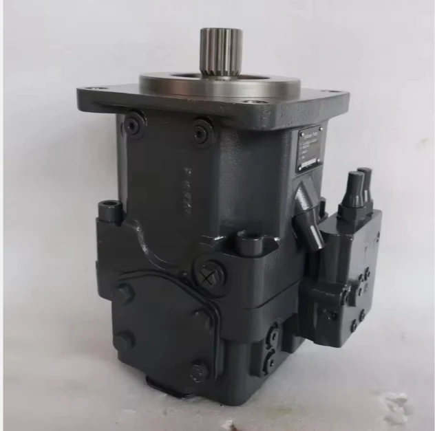
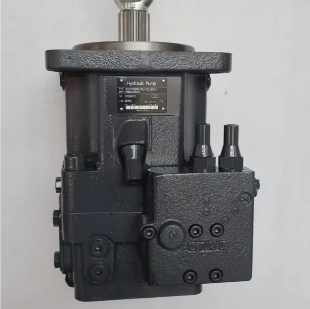

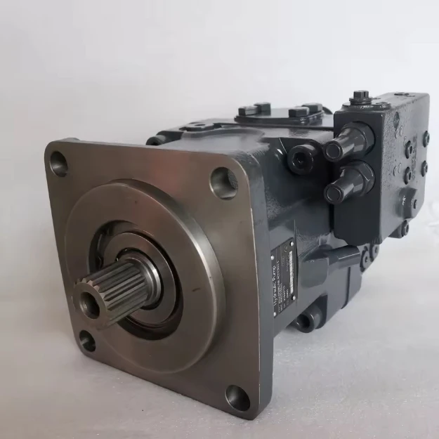
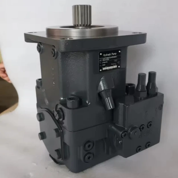
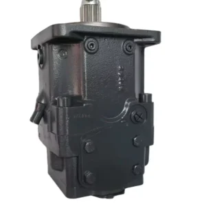
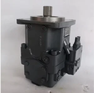
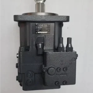
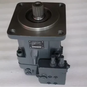
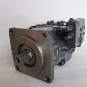
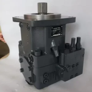
A11VO A11V Hydraulic Pump 40 60 75 130 190 260 Series A11VO75LRD/10R-NP012N00 Axial Piston Variable Open Circuit for Excavator
I. Core Technical Parameters 1. Basic performance parameters – Pump body type: Axial piston variable pump, integrated load
sensitive (LS) control mechanism and high-pressure relief valve, supports unidirectional rotation, suitable for medium and
high-pressure high-flow hydraulic systems – Displacement and pressure parameters: Rated displacement 75 cc/rev (the “75” in the
model corresponds to the displacement specification), variable displacement range 0-75 cc/rev; The rated working pressure is 280
bar, the maximum allowable pressure is 350 bar (short-term ≤10 seconds), the return oil back pressure is ≤5 bar, and the load
sensitive control pressure difference is ≤15 bar – Rotational speed and flow parameters: Rated rotational speed 2800 rpm, maximum
rotational speed 3600 rpm (short-term ≤5 minutes), minimum stable rotational speed 500 rpm; The maximum output flow at the rated
speed is 210 L/min (75 cc/rev×2800 rpm÷1000), and the flow regulation response time is ≤30 ms – Efficiency parameters: Rated
working condition volumetric efficiency ≥95%, total efficiency ≥90%; Load sensitive control accuracy ±1%, idle flow ≤3 L/min
(energy-saving mode) 2. Structure and connection parameters – Structural type: Cast iron one-piece formed pump body, surface
phosphating anti-rust treatment; Alloy steel plunger (hardness HRC62-65), copper-based alloy cylinder body, nitrided swash plate,
double-end mechanical seal + high-pressure lip seal combination; The centering spring type return mechanism is adopted to ensure
the reliable return of the plunger – Installation and connection specifications: Flange installation (compatible with ISO 3019-1
standard, “10R-NP012” corresponds to right-rotating installation positioning); Oil port thread: Suction port G2, outlet port G1
1/2, load-sensitive control oil port G1/8; The output shaft is connected by involute splines (12-tooth / 14-tooth options are
available). The overall weight is approximately 35 kg, and the external dimensions (length × width × height) ≈450×320×260 mm –
Protection grade: IP65, suitable for medium and large-sized construction machinery and industrial environments with dust, humidity
and vibration 3. Medium and Environmental requirements – Medium requirements: Compatible with L-HM 46/68 anti-wear hydraulic oil,
allowable medium viscosity range 15-400 mm²/s, moisture content ≤0.02%, solid particle size ≤5 μm – Environmental parameters:
Operating environment temperature -25℃ to 90℃, relative humidity ≤95%; The cleanliness of the oil should reach ISO 4406 13/10
grade (to be upgraded to 12/9 grade under high-pressure conditions). – Filtration requirements: A filter screen of ≥120 mesh
should be installed on the oil suction side. The filtration accuracy on the oil return side should be ≤10 μm. A high-pressure
filter (accuracy ≤5 μm) must be installed at the oil outlet. Ii. Working Principle This pump is an axial piston variable pump. Its
core realizes the conversion of mechanical energy and hydraulic energy and the matching of flow as needed through the mechanism of
“piston reciprocating volume change + load sensitive feedback regulation”. The specific process is as follows: 1. Core mechanism
of power transformation The motor drives the transmission shaft to rotate the cylinder block. Under the thrust of the centering
spring and the swash plate, the plunger moves back and forth in a straight line within the cylinder block holes. When the plunger
rotates with the cylinder block to the oil suction zone, the plunger extends outward, increasing the volume of the cylinder block
holes to form a vacuum, and the hydraulic oil is sucked in through the oil suction port. When the plunger rotates to the oil
pressure zone, the swash plate compresses the plunger to retract inward, reducing the volume of the cylinder block holes. The oil
is squeezed to generate high pressure and guided to the oil outlet through the distribution plate for discharge, driving the
actuator to act. 2. Variable regulation and protection mechanism Integrated load sensitive (LS) control mechanism and
high-pressure relief valve: The load sensitive valve collects the load pressure signal of the actuator in real time. When the load
pressure changes, the control oil pushes the variable piston to adjust the inclination Angle of the swash plate, thereby changing
the plunger stroke and displacement (0-75cc /rev), achieving on-demand supply of “the pump outputs the flow rate required by the
load”. When the system pressure exceeds the maximum allowable value of 350 bar, the high-pressure relief valve is fully open to
unload, guiding the oil back to the suction chamber to prevent overload damage to the pump body and the system. Iii. Product
Features and Advantages – Load-sensitive energy saving: The LS control mechanism enables the flow to match the load as needed,
saving 30% to 40% energy compared to fixed displacement pumps. In idle energy-saving mode, the flow rate is ≤3 L/min,
significantly reducing standby energy consumption. With a 30-ms rapid response time, there is no lag in traffic replenishment when
the load suddenly changes – High pressure, high efficiency and stability: With a rated pressure of 280 bar, it is suitable for
medium and high pressure scenarios, and a 95% high volumetric efficiency reduces energy loss. The copper-based cylinder body is
precisely fitted with alloy steel plungers, with a clearance of no more than 0.005mm and a flow pulsation rate of no more than
1.5%, meeting the requirements of high-precision control – High wear resistance and long service life: The plunger and swash plate
are treated with nitriding hardening, and the cylinder block surface is laser-coated with a wear-resistant layer. The wear of key
friction pairs is ≤ 0.01mm per 10,000 hours. The double-seal combination design ensures a static leakage of no more than 0.5
mL/min and a trouble-free operating life under rated conditions of no less than 20,000 hours – Wide working condition
adaptability: A wide temperature range of -25℃ to 90℃ is suitable for high and low temperature operations. With an IP65 protection
rating, it can withstand the bumpy and dusty environments of construction machinery. It supports two installation methods: flange
and foot seat. The oil port can be rotated 180° for adjustment to adapt to different equipment layouts Iv. Usage Functions and
Purposes 1. Core usage functions – Variable flow on-demand fuel supply: The displacement (0-75cc /rev) is adjusted in real time
according to the load of the actuator to provide precise power for fluctuating loads, avoiding energy waste and oil temperature
rise caused by flow redundancy – High-pressure power transmission: With a rated pressure of 280 bar, it can drive heavy-duty
actuators, achieving high thrust/torque output. It can replace the parallel connection of multiple low-pressure pumps and enhance
system integration – Dual system protection: Load-sensitive control enables dynamic pressure regulation, high-pressure relief
valves provide overload protection, and integrated interfaces for early warning of excessively high oil temperature and oil
contamination enhance system safety 2. Main uses As a core power component of medium and high-pressure high-flow hydraulic
systems, it connects high-power motors with heavy-duty actuating elements, providing energy-saving high-pressure power for
heavy-load and variable load scenarios of various medium and large-sized construction machinery and industrial heavy equipment. It
is a key core component of heavy-duty hydraulic transmission systems. V. Applicable Machines and Scenarios 1. Adapt to the core
machine – Construction machinery: Main working system of 15-30 ton excavators, lifting and steering system of 8-12 ton loaders,
lifting and luffing mechanism of 25-50 ton truck cranes, drive system of hydraulic bulldozers – Industrial machinery: Injection
systems for 800-1500 ton die-casting machines, roller adjustment mechanisms for heavy steel rolling equipment, clamping systems
for large injection molding machines, drive systems for cutting heads of mine boring machines – Special equipment: Ship hydraulic
propulsion systems, port gantry crane hoisting mechanisms, hydraulic cylinder drive systems for metallurgical equipment, power
sources for large hydraulic test benches 2. Typical application scenarios In heavy-load scenarios of excavators: As the main pump
of a 20-ton excavator, when the rated pressure is 280 bar and the maximum flow rate is 210 L/min, it drives the three actuating
elements of the boom, bucket arm and bucket to act in a compound manner. Load sensitive control reduces the fuel consumption of
the compound action by 35%, and the oil temperature is ≤65℃ after continuous operation for 8 hours – Die-casting machine injection
scenario: Equipped with a 1200-ton die-casting machine injection system, the displacement rapidly increases from 0 to 75 cc/rev
during the injection stage, and the pressure rises to 320 bar (short time) within 0.3 seconds. The injection speed is ≥5 m/s,
meeting the requirements of high-pressure die-casting of aluminum alloys. The volumetric efficiency is 95%, ensuring injection
accuracy of ±0.2 mm – Crane lifting scenario: Drive the main lifting mechanism of a 30-ton truck crane. When unloaded, the
displacement drops to 5 cc/rev for energy-saving standby. When fully loaded, the displacement instantly rises to 75 cc/rev. The
280 bar pressure drives the lifting motor to achieve stable lifting at 1.5 m/min, with load-sensitive response and no impact Six.
Similar models 1. Different models of the same series displacement -A11VO60LRD /10R-NP012N00: Rated displacement 60 cc/rev,
maximum flow rate 168 L/min, rated pressure 280 bar, suitable for medium high-pressure systems (such as 15-ton excavators, 800-ton
die-casting machines), volume 18% smaller, weight approximately 28 kg -A11VO95LRD /10R-NP012N00: Rated displacement 95 cc/rev,
maximum flow rate 266 L/min, maximum pressure 350 bar, suitable for ultra-large high-pressure systems (such as 30-ton excavators,
1500-ton die-casting machines), with a 27% power increase 2. Models with the same displacement but different functions -A11VO75LDD
/10R-NP012N00: Electro-hydraulic proportional control model, supporting PLC remote adjustment of displacement and pressure,
control accuracy ±0.5%, suitable for fully automatic production lines, with a 50% higher cost -A11VO75LRM /10R-NP012N00: Manual
variable adjustment mechanism model, suitable for simple high-pressure systems with fixed pressure and flow. It features a simple
structure and a 25% lower cost -A11VO75LLD /10L-NP012N00: Left-rotating installation model, suitable for equipment with limited
motor rotation direction. The oil outlet direction is reversed. Other performances remain the same as the original model
A11VO60LRDS/10R-NSC12K02 A11VO95LRDS/10L-NSD12N00 A11VO75LDRS/10L-NZD12N00 A11VO145LRDS/11R-NZD12N00 A11VLO190LRDS/11R-NZD12N00
A11VLO260LRDS/11R-NZD12N00 A11VLO190DR/11R-NPD12N00 A11VLO190DRG/11R-NPD12N00 A11VLO190DRS/11R-NPD12N00 A11VO190DR/11R-NPD12N00
A11VO190DRG/11R-NPD12N00
A11VO190DRS/11R-NPD12N00 A11VLO190EP2/11R-NPD12N00 A11VLO190LRDU2/11R-NZD12K02P-S A11VLO190LRDU2/11R-NZD12K83P
A11VLO190LRDU2/11R-NZD12K84P A11VLO190LRDS/11R-NSD12K01 A11VLO190LRDS/11L-NSD12K01 A11VLO190LE2S/11R-NZG12K04
A11VLO190LRDH2/11R-NZD12K02 A11VLO190LRDH2/11R-NZD12K01 A11VLO260DR/11R-NZD12N00 A11VLO260DR/11R-NPD12N00
A11VLO260DRG/11R-NPD12N00 A11VLO260DRS/11R-NPD12N00 A11VO260DR/11R-NPD12N00 A11VO260DRG/11R-NPD12N00 A11VO260DRS/11R-NPD12N00
A11VLO260EP2/11R-NPD12N00 A11VLO2600LRDU2/11R-NZD12K02P-S A11VLO260LRDU2/11R-NZD12K84P A11VLO2600LRDH2/11R-NZD12K02
A11VO145LRDS/11R-NZD12N00 A11VO145LRDS/11R-NZD12K83 A11VLO145LRDS/11R-NSD12K02 A11VLO145LE2S/11R-NZG12K07
A11VLO145LE2S/11R-NZG12K04 A11VLO145LE2S/11R-NZG12K01 A11VO145LRDS/11L-NZD12N00 A11VO145LRDS/11L-NZD12K83
A11VLO145LRDS/11R-NZD12K01-Y A11VLO145LE2S/11L-NZD12K01P A11VLO145LRDS/11R-NZG12K07 A11VLO130LRDU2/10R-NZD12K02P-S
A11VLO130LRDH1/10R-NZD12K61 A11VLO130LRDH1/10R-NZD12K07 A11VLO130DRS/10R-NZD12K02 A11VLO130LRDS/10R-NSD12K02
A11VO130LRDS/10R-NZD12K07 A11VLO130LE2S/10L-NZD12K02P-K A11VO95LRDS/10R-NSD12N00 A11VO95LRDS/10R-NZD12K02
A11VO95LRDU2/10R-NZD12K02 A11VO95LRDS/10L-NSD12N00 A11VO95EP2D/10R-NZD12N00 A11VO95EP2D/10R-NZD12N82P A11VO75LRDS/10R-NSD12N00
A11VO75DR/10R-NPD12N00 A11VO75DRS/10L-NZD12K02 A11VO60DRS/10R-NSC12N00 A11VO60LRDS/10R-NZD12N00 A11VO40DRG/10R-NZC12K02
A11VO40DRG/10R-NPC12N00 A11VLO190DR/11R-NZD12N00 Vii. Precautions for Use Installation and commissioning When installing, ensure
that the coaxiality error between the pump shaft and the motor shaft is ≤ 0.08mm. Use a high-strength elastic coupling for
connection. Radial force (≥ 150N) must not be directly applied to the pump shaft to avoid the deviation of the swash plate’s
inclination Angle The oil suction pipeline should be short, straight and thick (length ≤2 meters, diameter ≥50 mm), the distance
between the oil suction port and the bottom of the oil tank should be ≥200 mm, and the filtration accuracy of the filter should be
≥120 mesh. The pipeline connection is fastened with double bolts. The sealing gasket is made of high-pressure resistant
fluororubber to ensure no air leakage. A vacuum gauge (vacuum degree ≤0.015 MPa) is installed on the oil suction side. Before the
first start-up, the pump chamber should be filled with clean hydraulic oil. Manually turn the pump 5 to 6 times to confirm that
the plunger can extend and contract flexibly. When starting up, first open the oil suction valve and run it no-load at low
pressure (100 bar) and low speed (1000 rpm) for 60 minutes. Gradually increase it to the rated parameter and calibrate the load
sensitive control pressure difference (set to 15 bar) at the same time. – Reverse rotation operation is prohibited; For outdoor
installation, a rain and dust-proof protective cover should be added. A heat dissipation space of ≥ 300mm should be reserved
around the pump body. When the ambient temperature exceeds 40℃, forced water cooling for heat dissipation is required 2. Operation
and Maintenance During operation, real-time monitoring of the pump body temperature (normal ≤85℃, maximum ≤95℃), outlet pressure
and noise is carried out. If the temperature rises sharply by more than 10℃, the pressure fluctuates by more than 8 bar or the
noise exceeds 78 dB, stop the machine immediately for inspection. Focus on checking the oil contamination level (once a month),
the wear of the plunger or the jamming of the load-sensitive valve – Regular maintenance cycle: Replace the hydraulic oil and the
three-stage filter every 3,000 hours; Disassemble and inspect every 15,000 hours. Replace the plunger when the diameter wear is ≥
0.02mm or the cylinder block hole is scratched. At the same time, replace the sealing parts and centering springs. Calibrate the
load-sensitive control accuracy and the pressure of the relief valve every 2000 hours It is strictly prohibited to run the engine
without oil (idling for more than 2 seconds can easily cause the plunger and cylinder block to be scratched). Do not operate for a
long time at the maximum pressure (350 bar) (no more than 5 seconds at a time). Before the system is shut down, it needs to be
reduced to low pressure and run no-load for 10 minutes. After the oil temperature is ≤60℃, the oil source should be cut off 3.
Storage and Protection When stored for a long time, all oil ports should be sealed with special plugs. Special anti-rust oil
(about 200 mL) should be injected into the pump cavity, and lithium-based grease should be applied to the splines of the output
shaft. Store in a dry warehouse with a temperature ranging from 0 to 45℃ and a humidity of no more than 60%. Avoid direct sunlight
and heavy object compression. Manually turn the wheel once every month Before putting the pump into use after being idle for more
than 12 months, thoroughly clean the pump cavity and pipelines, replace all seals and hydraulic oil, and regrind the mating
surface between the distribution plate and the cylinder body. Run the low-speed no-load test for 30 minutes to detect the variable
response and leakage (≤0.5 mL/min is normal). Only after meeting the standards can it be connected to the system


