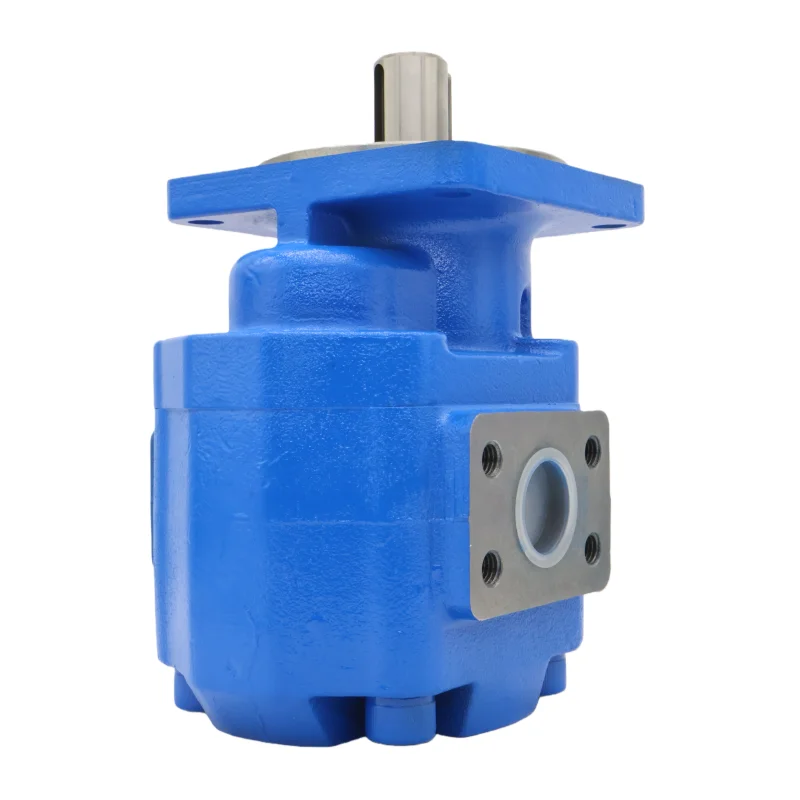


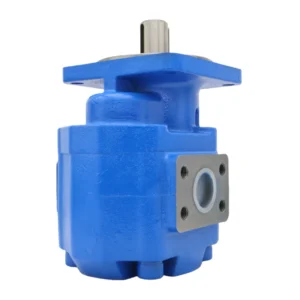

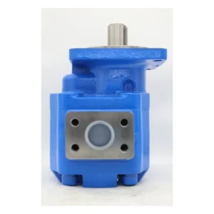

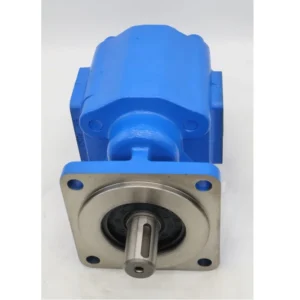

Hydraulic Gear Pump CBGH-2028 High Pressure Hydraulic Pump CBF CBG CBKL CBKP CBQ CBT CBW CBN CBGH CBGJ Oil Pump
Basic specifications
Type: CBGH series high-pressure external meshing double gear pump, suitable for hydraulic systems of construction machinery
Nominal displacement: Front pump 20ml/r, rear pump 28ml/r (In the model, “20” and “28” respectively represent the basic displacements of the front and rear pumps)
Rated pressure: 20-25MPa (depending on the version, 20 mpa for F series and 25MPa for G series)
Maximum working pressure: 28-31.5MPa (short-term peak)
Rated speed: 2000-2500r/min, recommended operating speed: 1500-2200r/min
Theoretical flow rate: approximately 40L/min for the front pump and 56L/min for the rear pump (displacement × rated speed ÷1000)
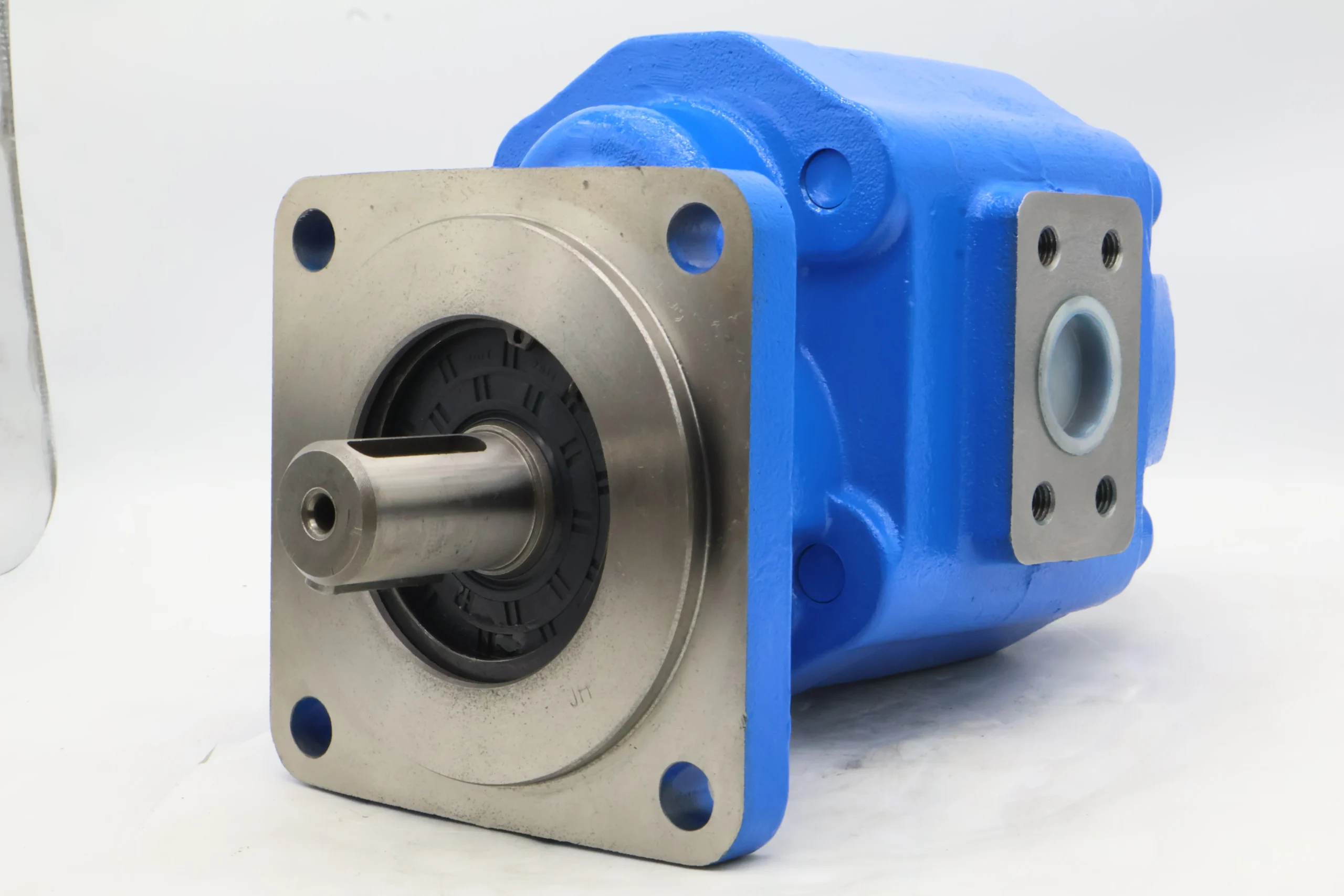
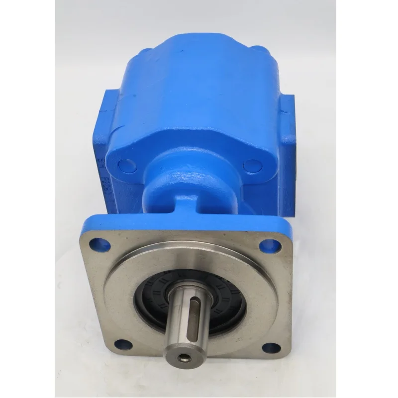
Drive shaft: Standard splined shaft (14 teeth or 21 teeth), shaft diameter approximately 32mm, and the standard rotation direction is clockwise (viewed from the shaft end)
Weight: Approximately 20-25kg, compact structure, and high power density
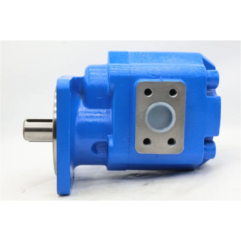
Installation method: Flange installation, standard rhombic flange or rectangular flange
Performance parameters
Volumetric efficiency: ≥90% (under rated conditions), ensuring high flow output
Overall efficiency: ≥80%, with highly efficient energy conversion
Applicable oil: L-HM anti-wear hydraulic oil, viscosity range 10-400mm²/s, recommended working viscosity 20-50mm²/s
Operating temperature: -20℃ to 80℃, ideal operating temperature 50±5℃
Oil cleanliness: ISO 4406 18/15 grade. A 60-100 mesh oil filter is required at the oil inlet
Noise level: ≤80dB (A), optimized fluid design, smooth operationIi. Working Principle
Working mechanism of external meshing double gear pump
Structural foundation
It is composed of two independent gear pumps at the front and rear, sharing a single drive shaft
Each pump unit consists of a driving gear, a driven gear, a pump body and front and rear side covers
A sealed working chamber is formed between the gear and the pump body, and a tiny gap (about 0.05-0.1mm) is maintained between the tooth tip and the inner wall of the pump body.
It adopts a three-piece structure, a high-strength aluminum alloy shell, and the key internal friction pairs have been hardened
Oil suction and discharge process
Oil suction stage: The drive shaft rotates the gear. In the oil suction chamber (disengaged side), the volume between the teeth increases to form a negative pressure. Under the action of atmospheric pressure, the oil is sucked in from the oil inlet and fills the space between the teeth
Oil transportation stage: The gears continue to rotate, and the oil is trapped between the teeth and the pump casing, and is pushed along the inner wall of the pump body from the oil suction chamber to the oil discharge chamber
Oil discharge stage: In the oil discharge chamber (entering the meshing side), the volume between the teeth decreases, and the oil is squeezed and discharged from the oil outlet, forming a continuous high-pressure oil flow
Double pumps working in coordination
The front pump (20ml/r) and the rear pump (28ml/r) rotate synchronously and can independently supply oil to different hydraulic circuits
The total output flow is the sum of the flow rates of the two pumps, which can simultaneously meet the flow requirements of different actuating elements
The internal design adopts axial clearance floating compensation and radial force balance to reduce leakage, improve efficiency and extend service life
Iii. Product Features and Advantages
1. High-efficiency performance features
High volumetric efficiency (≥90%) : Advanced axial clearance floating compensation technology is adopted to reduce internal leakage under high pressure
High pressure resistance capacity: Rated pressure 20-25MPa, peak up to 31.5MPa, suitable for high-pressure hydraulic systems
Stable flow: The dual-pump structure provides a more stable total output flow, reducing system pressure fluctuations
High power density: Large output power per unit weight, suitable for construction machinery with limited installation space
2. Reliability and durability
High-strength shell: Made of aluminum alloy or cast iron, it undergoes heat treatment and has strong resistance to deformation
Wear-resistant design: The gears are made of high-quality alloy steel and undergo surface hardening treatment (HRC58-62) to extend their service life
Anti-pollution ability: Compared with precision pumps such as plunger pumps, it is less sensitive to oil contamination and can adapt to harsh working environments
Mean time between failures: ≥ 8,000 hours, reducing maintenance frequency and downtime
3. Design and installation advantages
Double structure: Integrated design, space-saving and simplified pipeline connection
Multi-circuit oil supply: It can simultaneously provide power for two different hydraulic circuits, such as the working device and the walking system
Multiple installation methods: We offer various installation forms such as rhombic flanges and rectangular flanges to meet the requirements of different hosts
Easy maintenance: Modular design allows for separate disassembly and maintenance of the front and rear pumps, reducing maintenance costs
Iv. Usage Functions and Purposes
Core functions
Convert mechanical energy into hydraulic energy to provide a stable high-pressure oil source for the hydraulic system of construction machinery
The dual-pump design can simultaneously provide pressure oil of different flow rates for two independent hydraulic circuits
It works in conjunction with various control valves to achieve compound control of multiple actions for construction machinery
It has a certain self-priming ability, starts up quickly and does not require an additional oil priming device
Main application fields
Hydraulic system for construction machinery
The power source for the working devices (boom, bucket arm, and bucket) and the rotating system of the excavator
The working devices and steering systems of loaders and bulldozers
The vibration system and walking drive of the roller
Forklift lifting, tilting and steering systems
Hydraulic system for special vehicles
Dump truck body lifting system
The outriggers and boom systems of truck cranes
Fire truck ladder lifting and telescopic system
Garbage bin lifting and compression system for sanitation vehicles
Industrial hydraulic system
Auxiliary hydraulic systems for plastic machinery (injection molding machines, extruders)
The power systems of forging and pressing equipment such as presses and bending machines
Auxiliary hydraulic systems for metallurgical equipment and mining machinery
Agricultural machinery
Tractor hydraulic suspension system
Drive for the lifting of the header and the threshing wheel of the combine harvester
Hydraulic control system for agricultural machinery
V. Applicable Machines and Scenarios
1. Typical applicable machines
Excavator
For small and medium-sized excavators of 5-8 tons: The CBGH-2028 dual pump can simultaneously provide power for the working device (approximately 20-25 mpa) and the rotating system (approximately 16-20 mpa)
It is particularly suitable for working conditions such as urban construction and pipeline laying, where the load changes frequently but the system stability is highly required
Loader
3-5 ton class loaders: The front pump (20ml/r) supplies oil to the steering system, and the rear pump (28ml/r) supplies oil to the working device
The pressure requirement of the steering system is approximately 16-20 mpa, and that of the working device is about 20-25 mpa, which perfectly matches the performance of CBGH-2028
Forklift
3-5 ton forklifts: The front pump is responsible for the lifting system (high pressure, large flow), and the rear pump is responsible for the tilting and steering system (low pressure, small flow).
The system pressure is generally between 16 and 20MPa, and the flow requirement varies from 30 to 80L/min depending on the working conditions
Specialized vehicles
Dump truck: The dual-pump design can simultaneously meet the functions of rapid lifting of the lifting cylinder (for large flow) and locking of the cargo box (for pressure maintenance)
Truck crane: Provides independent fuel supply for the outrigger system (high-pressure stability) and boom extension and retraction (large flow)
2. Characteristics of applicable scenarios
Construction machinery requiring independent control of multiple circuits:
The excavator can perform both excavation and rotation operations simultaneously, and the CBGH-2028 can provide the required flow and pressure respectively
The system design is simplified, eliminating the need for additional diversion valve groups, thereby reducing costs and leakage risks
Applications with frequent load changes but high reliability requirements:
The load of construction machinery varies greatly under different working conditions. The CBGH-2028 has strong shock resistance and can adapt to frequent load changes
It can maintain stable operation even in harsh environments such as mines and construction sites
Small and medium-sized equipment with limited space
The integrated dual-pump design saves approximately 30% of the installation space compared to two independent pumps
It is lightweight (about 20-25kg), suitable for devices that are sensitive to weight
Hydraulic systems with high cost performance requirements
Compared with high-end pumps such as piston pumps, it is moderately priced and can meet the performance requirements of most construction machinery at the same time
Low maintenance cost, good universality of spare parts, and abundant market supply
Six. Similar models
1. Different specifications and models of the same series
CBGH-1620: Front pump 16ml/r, rear pump 20ml/r, suitable for 3-5 ton small construction machinery, such as small excavators and loaders
CBGH-2532: Front pump 25ml/r, rear pump 32ml/r, suitable for medium-sized construction machinery of 8-10 tons, with a larger flow output
CBGH-3240: Front pump 32ml/r, rear pump 40ml/r, suitable for large construction machinery of 10-15 tons, such as large excavators and rollers
2. Different series models of the same type
CBG2 series: A double gear pump similar to the CBGH series, with a rated pressure of approximately 16-20 mpa and a wider displacement range, from (10/10) to (80/80) ml/r
CBT-E series: High-pressure gear pump, rated pressure 20MPa, single pump structure, displacement ranging from 10 to 63ml/r, suitable for equipment requiring a single high-pressure oil source
CBH Series: High-pressure single gear pump, rated pressure 25MPa, displacement ranging from 20 to 80ml/r, suitable for machinery that only requires a single oil supply circuit
3. Domestic similar products
Hengli CBG series: Its performance is comparable to that of the CBGH series, but it has a more competitive price and has been widely used in domestic construction machinery
Eddie CBH series: Advanced manufacturing processes are adopted, and the key friction pair materials are upgraded. Some models can directly replace the CBGH series
Changjiang Hydraulic CB Series: A well-established domestic product with stable quality and affordable prices, it is widely used in the field of construction machinery
Vii. Precautions for Use
1. Installation points
Fixed foundation
The flatness of the installation plane should be ≤0.1mm to ensure the stability of the pump body and reduce vibration and noise
Tighten the fixing bolts evenly (with torque as per the specification requirements, approximately 40-60N · m) to prevent the shell from deforming
Shaft connection
Elastic couplings (such as membrane couplings) must be used for connection. Rigid connection is strictly prohibited
The coaxiality is controlled at ≤0.05mm (for elastic couplings) or ≤0.03mm (for rigid couplings) to reduce bearing wear
The pump shaft must not bear additional radial or axial loads and can only transmit torque
Pipeline connection
The diameter of the oil inlet pipe is ≥25mm and the length is ≤3m to reduce the oil suction resistance and prevent cavitation
The diameter of the oil outlet pipe should be ≥20mm to ensure that the pressure loss is within the allowable range
The oil drain pipe must be connected to the oil tank separately and not in parallel with the return oil pipe. The back pressure should be ≤0.3MPa to prevent damage to the oil seal
All pipelines should be thoroughly cleaned to ensure there are no iron filings, welding slag or other impurities. It is recommended to filter them with a 200-mesh filter screen
2. Startup and Operation management
Startup program
Check the oil level in the fuel tank (more than 200mm above the suction port) and the oil temperature (not lower than 10℃).
Manually turn the wheel 2 to 3 times to ensure there is no jamming
Loosen the plug of the oil drain port, expel all the air inside the pump, and then tighten it
Start the system under no-load conditions (set the system relief valve to the minimum pressure) and run it for 5 to 10 minutes until the oil temperature rises above 30℃
Gradually increase the pressure (each increase ≤30% of the rated pressure, with an interval of ≥2 minutes). It is strictly prohibited to directly load the cold machine at full load
Key points of operation monitoring
Oil temperature: Normal 40-65℃, not exceeding 80℃ at the maximum. (If the temperature exceeds the limit, stop the machine to check the cooling system or the viscosity of the oil.
Pressure: Not exceeding the rated pressure (20-25 mpa), peak ≤28MPa and cumulative time ≤10 minutes per hour
Noise: Smooth operation ≤80dB. Abnormal noise (>85dB) indicates possible wear or cavitation, and the machine should be stopped immediately for inspection
Leakage: Normal allowable trace leakage (<5 drops per minute). If the leakage increases, the sealing parts should be inspected and repaired in time
Vibration: The vibration is slight to the touch. If obvious vibration is felt, the machine should be stopped to check the centering condition or bearing wear
3. Maintenance and care
Daily inspection
Check the oil level, temperature, noise and leakage conditions every shift, and record the operating parameters
Check if the connecting bolts are loose and tighten them in time
Check the pressure difference of the filter. Replace the filter element in time if it exceeds the specified value
Regular maintenance
Every 250 hours:
When the pressure difference of the return oil filter exceeds 0.15MPa, the filter element must be replaced
Check whether the temperature distribution of the pump casing is uniform and determine if there is any abnormal wear inside
Every 500 hours:
Comprehensively inspect the seals and replace the aged or damaged sealing rings
Check the contamination level of the oil and take samples for testing if necessary
Every 1000 hours:
Change the hydraulic oil (while cleaning the oil tank and pipelines)
Check the gear meshing clearance (which should be within the range of 0.08 to 0.15mm) and the bearing clearance
Every 2000 hours:
Disassemble and inspect the wear of gears, shafts and bearings, and measure the fit clearance
Check whether the safety valve is working properly and reset the pressure value if necessary
Oil Product management
Hydraulic oils of different brands must not be mixed to prevent the reaction of additives and the formation of sediment
In cold regions (ambient temperature ≤-10℃), L-HV low-temperature hydraulic oil should be used to improve low-temperature fluidity
Regularly test the cleanliness of the oil to ensure compliance with ISO 4406 18/15 grade standards
When changing the oil, thoroughly clean the system to prevent the mixture of new and old oil from affecting performance
4. Special Precautions
It is strictly prohibited to operate without oil: Even a short period of dry running (>5 seconds) will cause the gears and pump body to sinter, resulting in irreversible damage
Prevent cavitation
Make sure the oil suction pipe is well sealed to prevent air from entering the system
The oil suction height should be ≤500mm, and it is recommended to be ≤300mm to reduce the oil suction resistance
If the oil temperature is too low (<10℃), run it no-load for 10 to 15 minutes first to raise the oil temperature before loading
The pressure drop of the oil suction port filter is less than 0.03MPa to prevent cavitation caused by excessive oil suction resistance
Load matching
Avoid long-term operation at the maximum pressure and maximum speed simultaneously (which will cause overheating and excessive wear).
When designing the system, the pump should operate within the range of 70-85% of the rated pressure to increase its service life
Avoid frequent starts and stops to reduce shock loads
Shutdown protection
Before shutting down, the load should be unloaded to low pressure (≤50bar) and run for 3 to 5 minutes. Only when the oil temperature drops below 60℃ should the power be cut off
Before long-term shutdown, it should be run without load for 10 minutes to completely relieve the system pressure and prevent the oil from oxidizing
For long-term storage, all oil ports should be sealed to prevent dust and it should be placed in a dry and well-ventilated area


