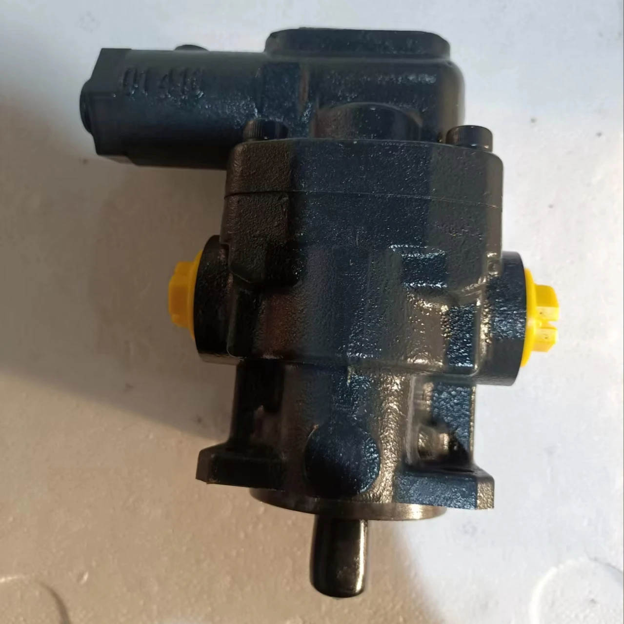
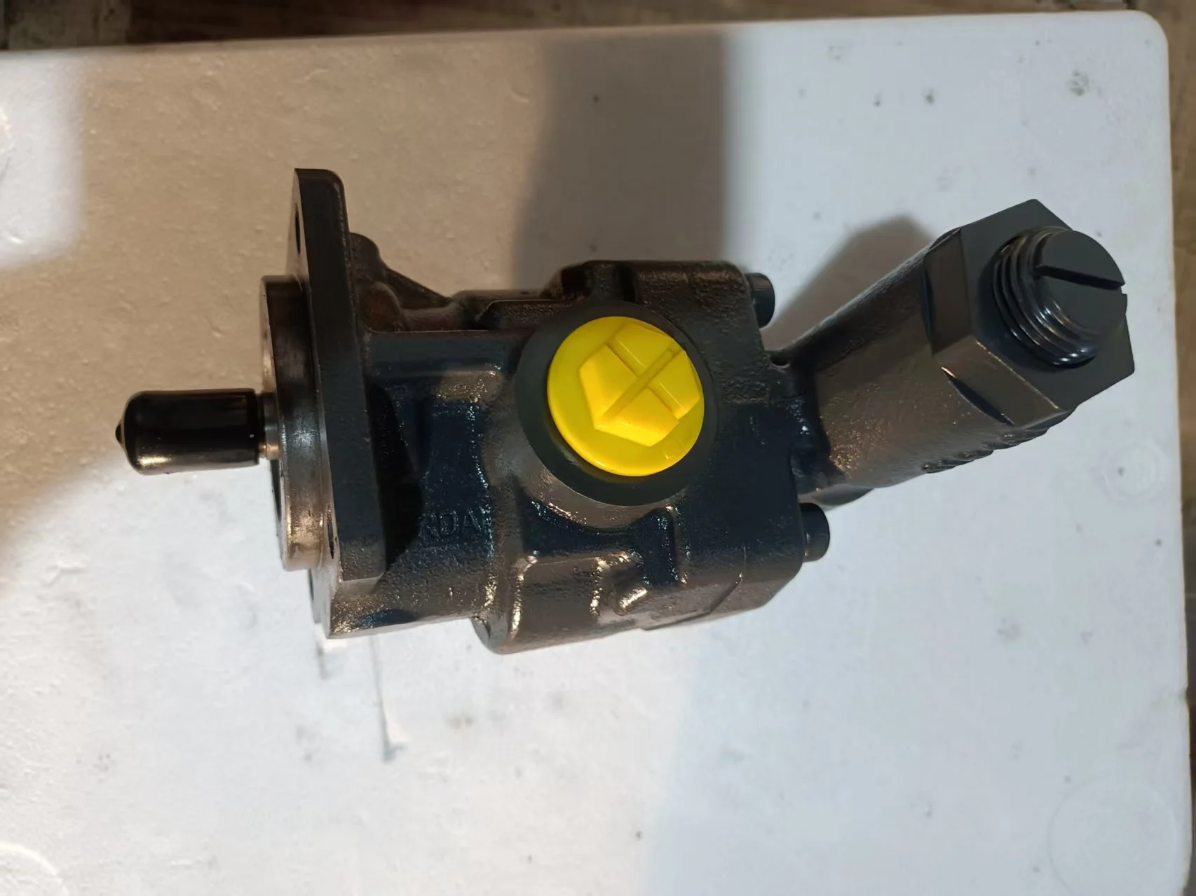
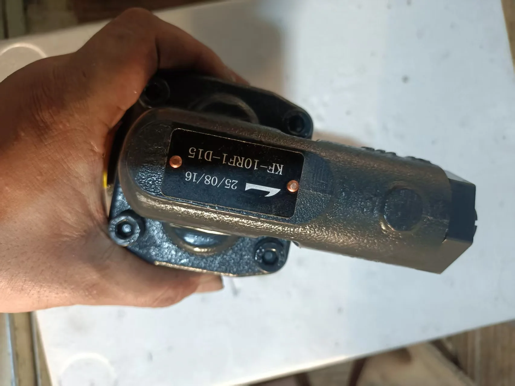
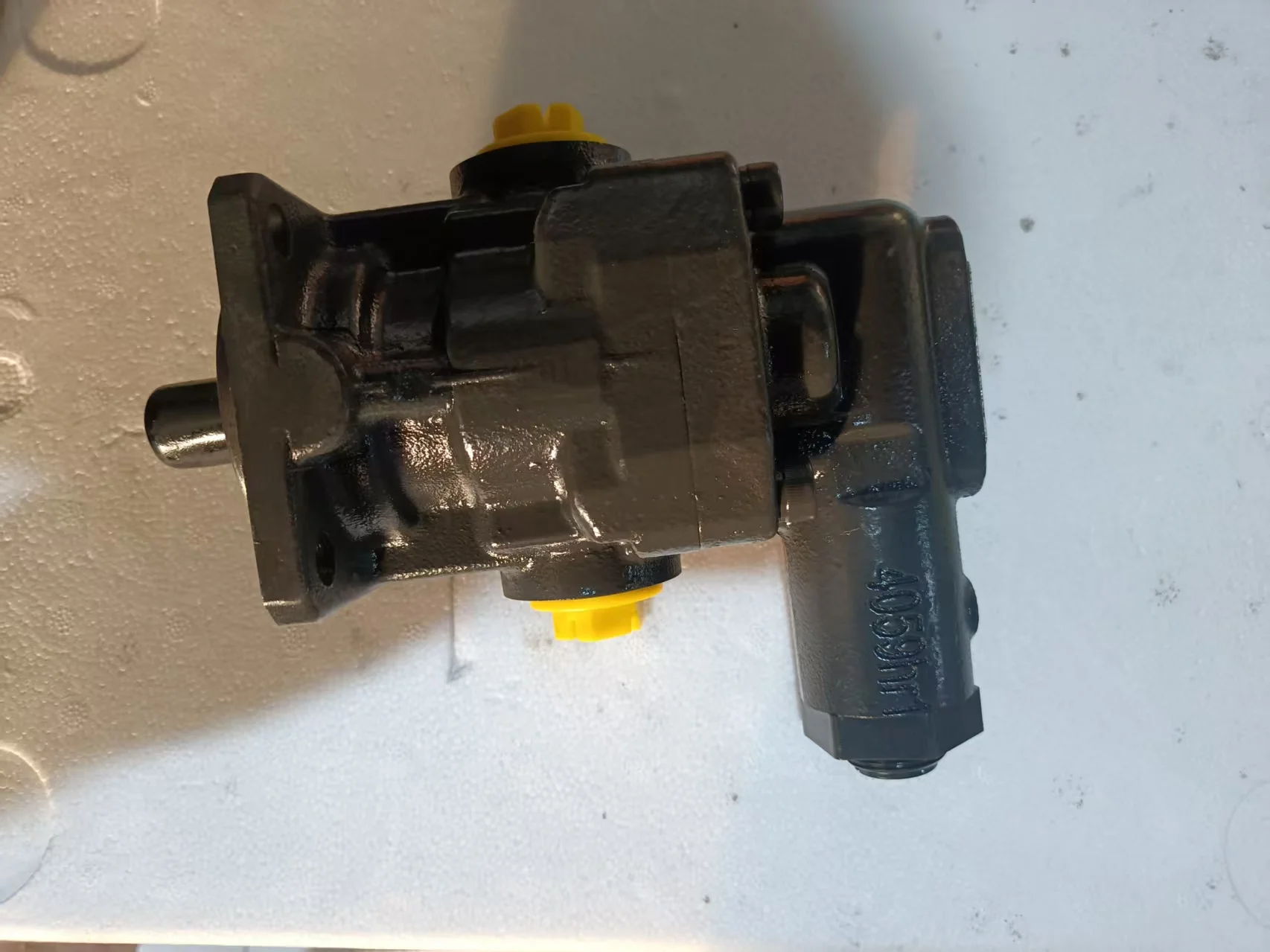
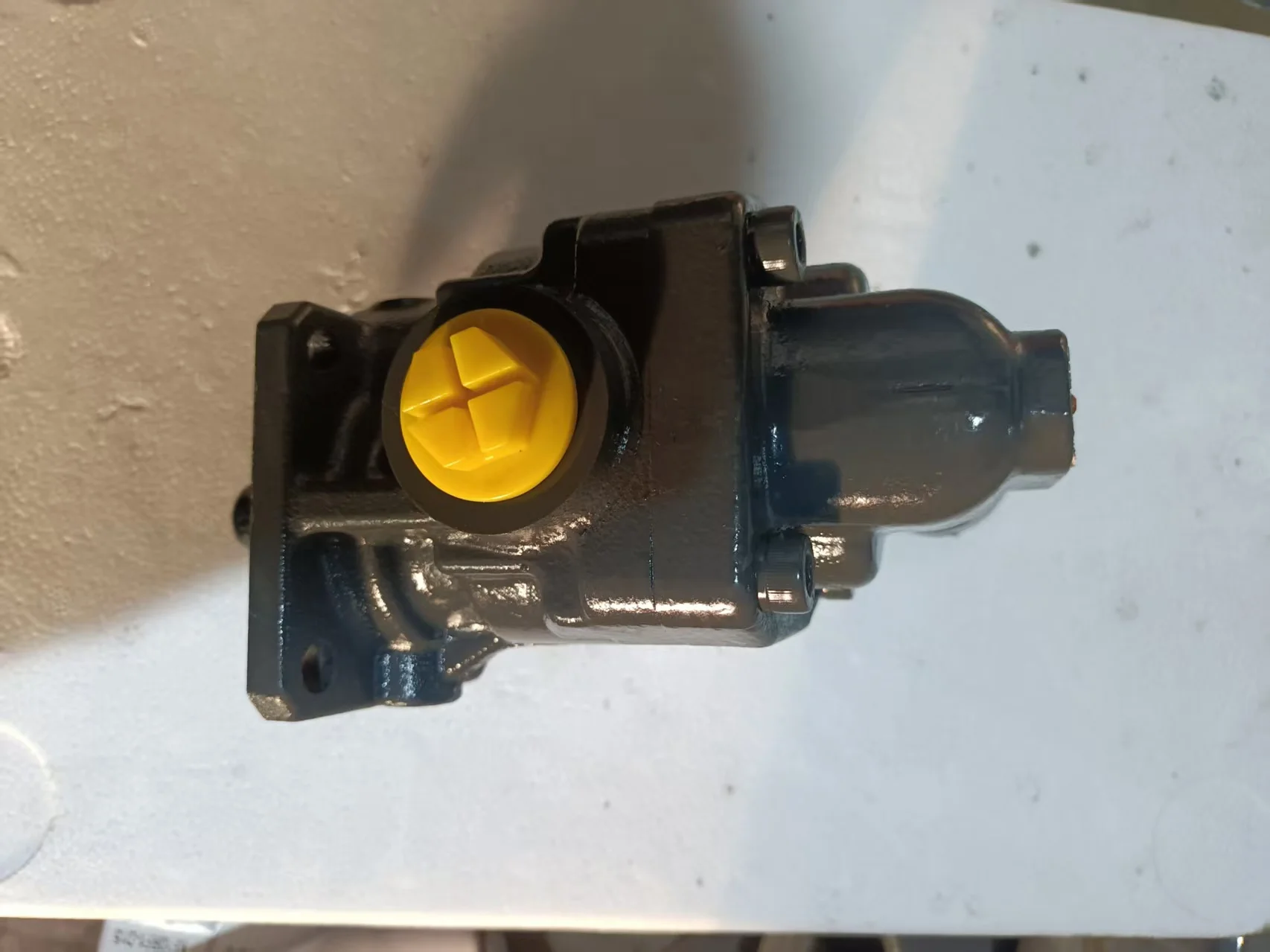
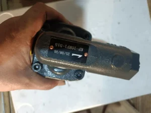


OEM KP KF KF25 KF32 KF40 Gear Pump KF-10RF1-D15 KF100RF1 KF112RF1 KF16RF2-D16 KF80RF1-D15 High Pressure Hydraulic Oil Pump
Basic specifications
Type: KF series external gear pump, 10 indicates nominal displacement of 10cc/rev, RF1 is the bearing and seal configuration code, and D15 indicates with a 15bar safety valve
Nominal displacement: 10cc/rev (10 milliliters of hydraulic oil per revolution), theoretical flow rate is approximately 15L/min at a rotational speed of 1500r/min
Rated pressure: 25bar (continuous operation), short-term peak up to 40bar, safety valve set value 16bar (adjustable as needed)
Speed range: 200-3000r/min, recommended working speed: 1500-2000r/min, minimum stable speed: ≥300r/min
Rotation direction: Right rotation (clockwise when viewed from the shaft end), and left rotation is available for some models
Weight: Approximately 3.5kg (excluding accessories), compact structure, easy to install
Working parameters
Volumetric efficiency: ≥90% (under rated conditions), high energy conversion efficiency
Overall efficiency: ≥80%, with stable comprehensive performance
Applicable medium: Hydraulic oil, lubricating oil, fuel oil and other non-corrosive liquids, free of solid particles
Medium viscosity: 12- 20,000 CST (mm²/s), optimal working viscosity: 20-60cSt
Medium temperature: -20℃ to +80℃, recommended working temperature: 30-55℃
Self-priming capacity: At startup, the allowable vacuum degree can reach -0.6 bar, and the suction lift can reach 4 meters (depending on the viscosity of the medium)
Noise level: <75dB (A), smooth operation, and good noise controlIi. Working Principle
Working mechanism of external gear pump
Core structure
It is composed of a pump body, front/rear end covers, a pair of intermeshing gears (driving wheel and driven wheel) and a safety valve
The gears are made of high-strength surface-hardened steel and are installed on special sliding bearings or needle roller bearings
The pump body and the end cover form a sealed cavity. The tooth tops and meshing lines of the gears divide the cavity into the oil suction chamber and the oil pressure chamber
Oil absorption process
When the driving gear is driven to rotate by the motor, it drives the driven gear to rotate in the opposite direction
On the oil suction side, the gear teeth gradually disengage from meshing, increasing the volume of the sealed working chamber and creating a local vacuum
The oil in the oil tank enters the pump chamber through the oil suction port under the action of atmospheric pressure, filling the gap between the teeth
Oil pressing process
The gear continues to rotate, and the oil is carried to the oil pressure side by the intertooth grooves
On the oil pressure side, the gear teeth gradually engage, the volume of the sealed cavity decreases, and the oil pressure rises
High-pressure oil is discharged into the system through the oil outlet, completing one working cycle
Safety valve function
When the system pressure exceeds the set value (16bar), the safety valve opens
Some of the oil flows back to the oil suction side to prevent system overpressure and protect the safety of the equipment
The safety valve setting value can be adjusted within the allowable range as needed (not exceeding the rated pressure at most).Iii. Product Features and Advantages
1. Structural and performance advantages
Simple and reliable: No complex valve groups, only one pair of meshing gears, low failure rate, average mean time between failures > 8,000 hours
Compact in size: With a compact structure and light weight, it is suitable for occasions where installation space is limited
Good self-priming performance: It can be started without additional priming of the pump, making it suitable for mobile devices and applications that require frequent starts and stops
Insensitive to contamination: Compared with plunger pumps and vane pumps, it has lower requirements for oil cleanliness (but still needs 10μm filtration).
2. Fluid conveying characteristics
Uniform flow: The output flow pulsation is small, making it particularly suitable for lubrication systems with high requirements for flow stability
Pressure stability: The safety valve provides overload protection to ensure that the system pressure remains within the set range
Wide application range: It can convey media of various viscosities, from low-viscosity lubricating oil to high-viscosity hydraulic oil
Bidirectional rotation: Some models can achieve bidirectional conveying by changing the rotation direction, adapting to the requirements of different working conditions
3. Maintenance and Economy
Easy maintenance: Modular design makes it easy to disassemble and replace worn parts
Long service life: The gears and bearings are made of wear-resistant materials, and the service life under normal working conditions is more than 5 years
High cost performance: Simple structure, low manufacturing cost, economical price, and low maintenance cost
Low energy consumption: High efficiency under rated working conditions, reducing system energy consumption and saving operating costs
Iv. Usage Functions and Purposes
Core functions
Convert mechanical energy into hydraulic energy to provide stable fluid power for the system
Precisely control the fluid flow to ensure the smooth operation of the actuating elements (such as hydraulic cylinders and hydraulic motors)
As the heart of the lubrication system, it provides necessary lubrication and cooling for mechanical equipment
Main application fields
Industrial lubrication system
Forced lubrication of reducers and gearboxes ensures the formation of an oil film between transmission components, reducing wear
Circulating lubrication of bearings and guide rails extends the service life of equipment
Centralized lubrication systems for large-scale mechanical equipment to enhance maintenance efficiency
Hydraulic auxiliary system
The pilot control oil circuit of construction machinery provides a stable low-pressure oil source
Ejection and mold lubrication systems for injection molding machines and die-casting machines
Lubrication and cooling of machine tool worktables and guide rails
Mobile device
Auxiliary pumps for the hydraulic systems of construction machinery (excavators, loaders)
Hydraulic steering and control systems for agricultural machinery (tractors, harvesters)
Hydraulic power units for ship deck machinery (such as winches and cranes)
Special applications
The gearbox lubrication system of wind power equipment ensures reliable operation in harsh environments
Core components of fluid conveying equipment such as oil filter trucks and fuel dispensers
The power source for hydraulic tools (such as hydraulic wrenches and hydraulic jacks)
V. Applicable Machines and Scenarios
1. Typical applicable machines
Lubrication system for wind turbine gearboxes
KF-10RF1-D15 is particularly suitable for forced lubrication of gearboxes in wind power equipment
It provides stable oil circulation in harsh environments with high altitudes and large temperature differences to ensure good lubrication of gears and bearings
The safety valve provides overload protection to prevent excessive system pressure caused by pipe blockage
Hydraulic auxiliary system for construction machinery
The pilot control system of the 8-ton excavator provides a low-pressure stable oil source
The lubrication system of the loader’s working device reduces the wear of the boom and bucket pin shafts
The hydraulic power source of the vibration system of the roller ensures the stability of the vibration frequency
Lubrication of industrial reducers
Built-in lubrication pumps for various industrial reducers, such as large reducers in metallurgical, mining and cement equipment
Provide sufficient lubricating oil flow under low-speed and heavy-load conditions to prevent tooth surface adhesion and bearing overheating
2. Characteristics of applicable scenarios
Mechanical transmission systems requiring continuous and stable lubrication:
For instance, gearboxes of papermaking machinery and textile machinery ensure the long-term stable operation of the equipment and reduce maintenance downtime
Hydraulic system with limited space
Such as small injection molding machines and die-casting machines, the compact design of the KF series can be directly installed inside the equipment
Low-noise working environment required
Such as food processing equipment and medical machinery, low-noise operation does not affect the working environment or product quality
Mobile or portable devices:
Such as hydraulic tools and small hydraulic stations, the lightweight design makes them easy to carry and install
Applications that need to prevent system overload:
For lubrication systems and hydraulic auxiliary circuits, the D15 safety valve provides reliable protection to prevent equipment damage
Six. Similar models
1. Different specifications and models of the same series
KF6RF1-D15: Displacement 6cc/rev, lighter in weight (about 3kg), suitable for small equipment and systems with lower flow requirements
KF16RF1-D15: Displacement 16cc/rev, with a larger output flow rate (approximately 24L/min at 1500rpm), suitable for medium-sized equipment
KF25RF1-D15: Displacement 25cc/rev, with greater output flow and pressure, suitable for lubrication systems that require larger flow rates
2. Different series models of the same type
KF10RF2-D15: Compared with KF10RF1-D15, it adopts different bearing and sealing configurations and is suitable for higher pressure conditions (up to 30bar).
KF10RF7-D15: Special sealing design, suitable for high-temperature environments (up to 120℃) and high-pressure applications
KF10RG series: It adopts needle roller bearings instead of sliding bearings, which have a stronger load-carrying capacity and are suitable for heavy-duty working conditions
3. Domestic alternative products
CBF-E10 series: Domestic gear pumps, with performance close to that of KF10RF1-D15, but more economical in price, suitable for applications with limited budgets
YBC series: Domestic high-performance gear pumps, featuring new sealing materials, have been improved in terms of high temperature and high pressure
Other brands of 10cc/min gear pumps, such as DK-10-RF-D15, can directly replace KF10RF1-D15, with slight differences in some parameters
KF4RF1-D15
KF4RF2-D15
KF4RF7-D15
VC0.025F1PS
VCA0.04FFR1
KF5RF1-D15
KF5RF2-D15
KF5RF7-D15
VC0.04F1PS
VCN0.04FFR1
KF6RF1-D15
KF6RF2-D15
KF6RF7-D15
VC0.1F1PS
VCA0.1FER1
KF8RF1-D15
KF8RF2-D15
KF8RF7-D15
VC0.2F1PS
VCA0.2FAR1
KF10RF1-D15
KF10RF2-D15
KF10RF7-D15
VC0.4F1PS
VCA0.2FBR1
KF12RF1-D15
KF12RF2-D15
KF12RF7-D15
VC1F1PS
VCN0.2FAR1
KF16RF1-D15
KF16RF2-D15
KF16RF7-D15
VC3F1PS
VCA2FCR1
KF20RF1-D15
KF20RF2-D15
KF20RF7-D15
VC5F1PS
VCA2FBR1
KF25RF1-D15
KF25RF2-D15
KF25RF7-D15
VC12F1PS
VCA2FCP1
KF32RF1-D15
KF32RF2-D15
KF32RF7-D15
VC16F1PS
VCA2FBP1
KF40RF1-D15
KF40RF2-D15
KF40RF7-D15
VC0.2F4PS
VCA5FER1
KF50RF1-D15
KF50RF2-D15
KF50RF7-D15
VC0.4F4PS
VC5F4PS
KF63RF1-D15
KF63RF2-D15
KF63RF7-D15
VC1F4PS
KF12 RF2 10.06 360PSI
KF80RF1-D15
KF80RF2-D15
KF80RF7-D15
Vii. Precautions for Use
1. Installation points
Fixed foundation
The installation plane must be flat (flatness < 0.1mm) to prevent the pump body from deforming and affecting the gear meshing
Tighten the fixing bolts evenly to prevent uneven force on the shell and leakage
Pipeline connection
The suction pipe diameter should be no less than 25mm and the length less than 2m to reduce suction resistance and prevent cavitation
The diameter of the oil drain pipe should be no less than 20mm to ensure that the pressure loss is within the allowable range (<5bar).
The oil suction pipeline must be well sealed to prevent air from entering the system and forming bubbles
The connection between the oil inlet and outlet must use O-rings or combined seals to ensure no leakage
Shaft connection
Elastic couplings (such as membrane couplings) must be used, and rigid connections are strictly prohibited
Coaxiality error is less than 0.05mm, angular deviation is less than 0.5°, reducing vibration and bearing load
No radial or axial loads shall be applied to the pump shaft. All loads must be borne by the coupling
2. Startup and Operation management
Startup program
Check the oil level in the fuel tank (at least 200mm above the suction port) and the oil temperature (not lower than -10 ℃).
Manually turn the wheel 2 to 3 times to ensure there is no jamming
Loosen the exhaust plug, start the pump to fill the pump cavity with oil until continuous oil is discharged, then tighten it
Start the machine without load and run it for 3 to 5 minutes to observe if there are any abnormal noises or leaks
Gradually load. It is strictly prohibited to directly load the cold machine to full load (each pressure increase ≤30% of the rated pressure, with an interval of ≥2 minutes).
Operation monitoring
Oil temperature: Normal operating temperature is 30-55℃. If the temperature exceeds 70℃, the machine should be shut down to check the cooling system
Pressure: Not exceeding the rated value (25bar). The opening pressure of the safety valve (16bar) should be calibrated regularly
Noise: Smooth operation <75dB. Abnormal noise (>80dB) indicates possible wear or cavitation, and the machine should be stopped immediately
Leakage: Slight seepage (<5 drops per minute) is allowed. If the leakage increases, timely maintenance is required
3. Maintenance and care
Daily inspection
Check the oil level, temperature, noise and leakage conditions every shift, and record the operating parameters
Check if the connecting bolts are loose and tighten them in time
Clean the surface of the pump body to prevent the accumulation of oil stains from affecting heat dissipation
Regular maintenance
Every 250 hours: Check the pressure difference of the filter (<0.15MPa), and replace the filter element if necessary
Every 500 hours: Check the contamination level of the oil (≤ISO 4406 19/16 grade), and take samples for testing if necessary
Every 1000 hours: Change the hydraulic oil and clean the oil tank and filter at the same time
Every 2000 hours: Conduct a comprehensive disassembly and inspection to measure the wear of gears and bearings, and replace them if necessary
Oil Product management
Hydraulic oils of different brands must not be mixed to prevent the reaction of additives and the formation of sediment
In cold regions, low-viscosity hydraulic oil (such as L-HV series) should be used to ensure low-temperature starting performance
Regularly test the viscosity and acid value of the oil to ensure they meet the usage requirements
4. Special Precautions
Prevent dry running
It is strictly prohibited to start the pump without oil. Even short-term dry operation will cause severe wear of gears and bearings
After a long period of inactivity, when restarting the pump, clean hydraulic oil should be filled into it
Prevent cavitation
Ensure that the oil suction pipeline is well sealed to prevent air from entering the system
The oil suction height should be less than 500mm, and it is recommended to be less than 300mm to reduce the oil suction resistance
When the oil temperature is too low (<10℃), run it no-load for 15 minutes first to increase the oil temperature before loading
Medium selection
Only lubricating liquids can be conveyed. It is strictly prohibited to convey media containing solid particles or corrosive substances
The viscosity of the liquid being conveyed must be within the specified range. If the viscosity is too high, it will cause motor overload; if it is too low, it will affect the pump efficiency
Safety valve maintenance
Regularly check whether the safety valve is flexible to prevent jamming and affecting the protective function
The setting value adjustment of the safety valve should be carried out by professionals. It is strictly prohibited to adjust it privately beyond the rated pressure range


