


Proportional Directional Control Pressure Valve 24EI1-H10B-T 24BI3-H6B-T 24BI1-B10H-T Hydraulic Solenoid Ball Valve 24EI1 34EI1
Core performance parameters
– Valve type: Electromagnetic directional control valve, two-position four-way structure, normally closed design, suitable for high-pressure hydraulic circuits. It controls the oil circuit to change direction through electromagnetic signals, achieving the action switching of the actuator.
– Pressure and flow parameters: Rated working pressure 31.5 MPa, maximum allowable pressure 35 MPa (short-term ≤5 seconds); Rated diameter: 10 mm, rated flow rate: 60 L/min, maximum flow rate: 80 L/min (when pressure drop ≤0.5 MPa).
– Control and response parameters: The control mode is DC electromagnetic drive, with a rated control voltage of DC 24V (allowing fluctuation of ±10%). The rated control power is 15 W, the commutation response time is ≤0.12 seconds, and the reset method is spring reset.
– Operating characteristics: Working oil temperature range: -20℃ to 100℃; The leakage at rated pressure is ≤3 mL/min. The electromagnetic coil has a protection grade of IP65 and a rated working condition fault-free life of ≥1 million commutations.
2. Structure and connection parameters
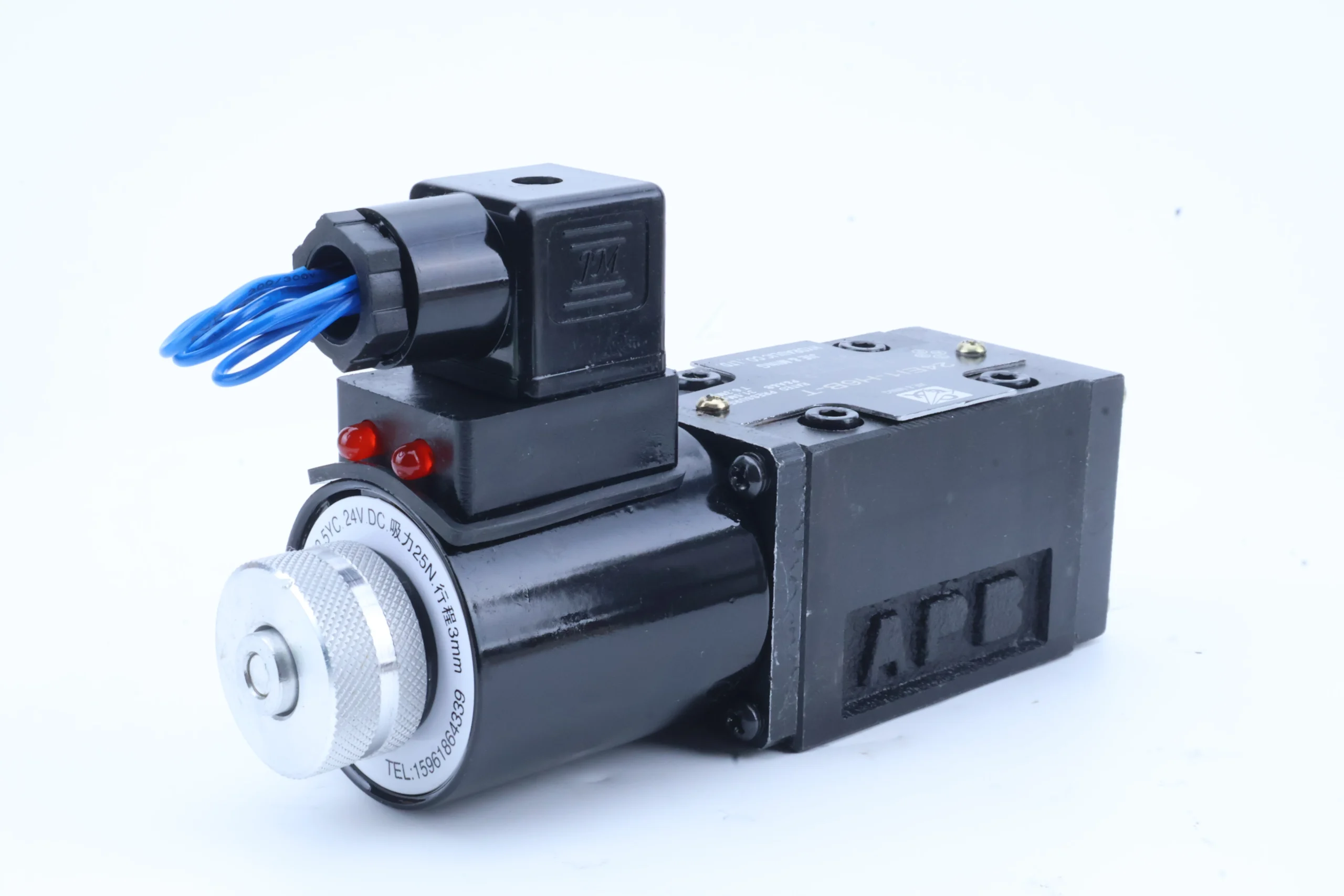
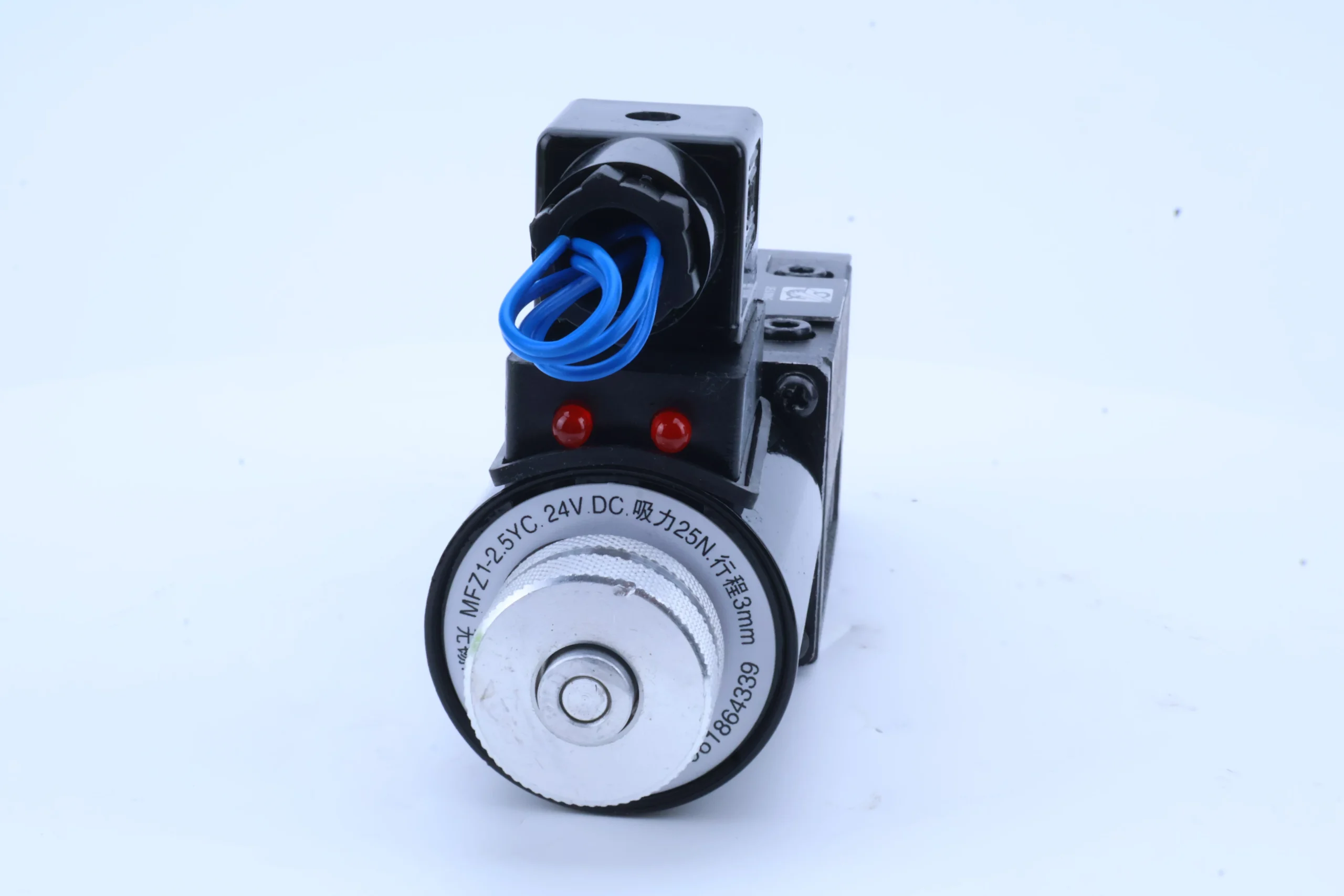
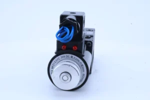
– Structural type: Spool valve core structure, integrating electromagnetic coil, reset spring, valve core, valve sleeve and sealing assembly; It adopts a plate installation design, with an O-shaped (enclosed) center function and is equipped with a manual emergency reversing button.
– Core material: The valve body is made of carbon steel (quenched and tempered, hardness HB220-250); The valve core is made of stainless steel 304 (hardness HRC35-40). The core of the electromagnetic coil is made of pure iron for electrical purposes. The sealing part is a high-pressure resistant fluororubber combination (temperature resistance ≤120℃).
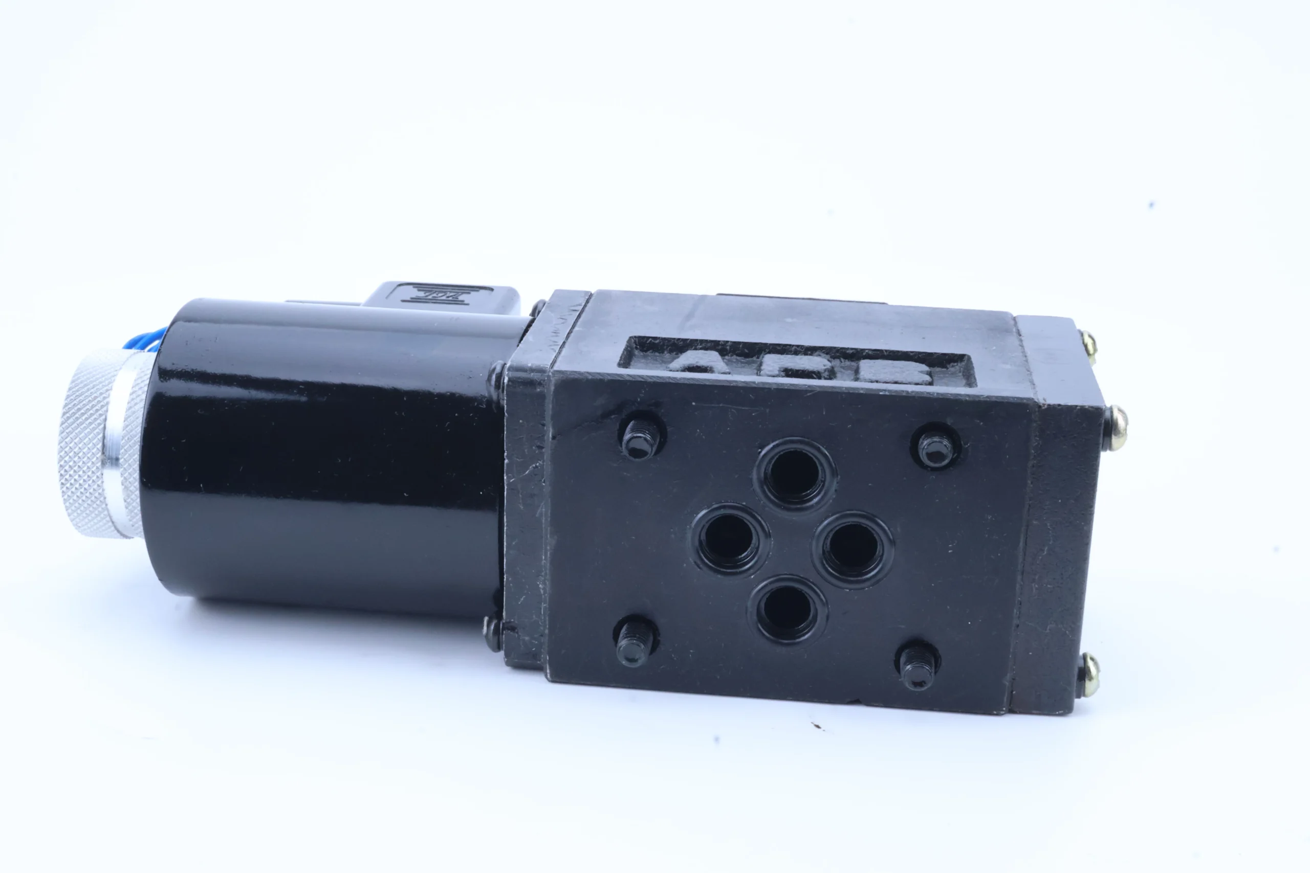
– Connection specifications: The oil inlet (P), return oil port (T), and working oil port (A/B) are all G3/4 threaded connections. The center distance of the installation holes is arranged in accordance with the standard layout (63×100 mm). The weight of the valve body is approximately 3.2 kg, and its external dimensions (length × width × height) ≈180×90×120 mm.
3. Medium and Environmental requirements
– Medium requirements: Compatible with L-HM 32/46/68 anti-wear hydraulic oil, allowing medium viscosity of 10-400 mm²/s; Moisture content ≤0.05%. It is strictly prohibited to use media containing solid particles (particle size > 5 μm) or corrosive media.
– Cleanliness standard: The oil cleanliness must reach ISO 4406 15/12 grade. A 10 μm fine filter must be installed before the valve. The filter should be replaced immediately when the pressure difference of the filter is greater than 0.1 MPa.
– Environmental parameters: Operating environment temperature -20℃ to 80℃, relative humidity ≤95% (short-term condensation is allowed); With a protection grade of IP65, it is suitable for scenarios such as construction machinery, industrial hydraulic stations, and automated production lines.Ii. Working Principle
This valve is a direct-acting electromagnetic directional control valve. Its core realizes the reversing of the hydraulic circuit through the mechanism of “electromagnetic force drive – valve core displacement – oil circuit switching”. The specific process is as follows:
1. Normal (power-off) state
When not powered on, the valve core is in the initial position under the force of the reset spring. The normally closed design cuts off the oil inlet (P) from the working oil port (A), and connects the working oil port (B) with the return oil port (T). The actuator has no power input and maintains its initial position under the load, with the oil circuit in a pressure-holding state.
2. Reversing (powered on) state
After the electromagnetic coil is supplied with a DC 24V voltage, an electromagnetic suction force is generated to overcome the spring force, driving the valve core to move along the axial direction of the valve sleeve to the working position, achieving oil circuit switching: the oil inlet (P) is connected to the working oil port (B), and high-pressure oil enters the rodless cavity of the actuator. At the same time, the working oil port (A) is connected to the return oil port (T), and the oil in the rod cavity flows back, driving the actuator to act. After the coil is de-energized, the valve core returns to its original position under the action of the spring, and the oil circuit returns to normal.
3. Emergency response and protection mechanism
It is equipped with a manual emergency knob. When the electromagnetic control fails, the valve core can be manually pushed to reverse. The valve core and valve sleeve are precisely ground (fit clearance ≤ 0.008mm) to reduce internal leakage. The coil is equipped with built-in overheat protection. It will automatically cut off power when the temperature exceeds 120℃ to prevent burnout.
Iii. Product Features and Advantages
– High-pressure and high-flow compatibility: With a rated pressure of 31.5MPa and a diameter of 10mm, it features a stable flow rate of 60 L/min, capable of driving the actuators of equipment ranging from 10 to 30 tons. It combines high-pressure pressure resistance with flow capacity, making it suitable for medium and heavy-duty hydraulic systems.
– Fast and precise reversing: The reversing response time is ≤0.12 seconds, which is 25% faster than that of ordinary solenoid valves. It can achieve high-frequency action switching of the actuator (such as industrial grasping by hydraulic manipulators), improving the operational efficiency of the equipment.
– Reliable and durable: The carbon steel valve body is impact-resistant, and the stainless steel valve core is corrosion-resistant. Combined with the precise grinding process, the rated working condition fault-free life is ≥1 million times. The IP65 protection rating can be adapted to outdoor working conditions with a lot of dust and high humidity.
– Convenient installation and operation and maintenance: The plate installation design is compatible with the layout of standardized hydraulic stations, and the installation space is 30% less than that of cartridge valves. It is equipped with a manual emergency knob, allowing for emergency operation in case of power failure. The vulnerable parts are highly versatile and easy to replace.
Iv. Usage Functions and Purposes
1. Core usage functions
– Oil circuit reversing control: By switching the inlet and return oil circuits through electromagnetic signals, it realizes the switching of actions such as extension and rotation of the actuator (hydraulic cylinder, hydraulic motor), adapting to the dual action requirements of “extension-retraction” and “forward rotation – reverse rotation”.
– Median pressure holding function: The median O-type machine can seal all oil ports, and the actuator can remain in position for a long time (such as pressure holding by hydraulic fixture clamping), with a pressure holding accuracy of ±0.3 MPa.
– Emergency manual control: When the electromagnetic control fails, manually rotating the emergency knob can drive the valve core to reverse direction, ensuring that the equipment completes emergency actions (such as returning construction machinery to its original position and removing workpieces).
2. Main application fields
In the field of construction machinery: 10-30 ton wheel loaders (lifting and tipping bucket circuits), 20-30 ton crawler excavators (boom and bucket arm circuits), small hydraulic crushing stations (hammer control circuits), suitable for infrastructure and mining operations.
– Industrial equipment field: 500-1000 ton hydraulic bending machines (main cylinder reversing circuit), large injection molding machines (mold closing and ejection circuits), hydraulic manipulators for automated production lines (grasping and assembly circuits), suitable for precision manufacturing operations.
– Special fields: Small port cranes (luffing circuit), mine tunnel boring machines (propulsion cylinder control circuit), garbage compression equipment (compaction mechanism circuit), suitable for continuous heavy-load operations.
V. Applicable Machines and Scenarios
1. Adapt to the core machine
– Construction machinery: 10-30 ton wheel loaders, 20-30 ton crawler excavators, small hydraulic crushing stations, 80-150 ton truck cranes.
– Industrial equipment: 500-1000 ton hydraulic bending machines, 600-1000 ton injection molding machines, automated hydraulic manipulators, hydraulic systems for medium-sized CNC lathes.
– Special equipment: Small port cranes, mine boring machines, 3-5 cubic meter garbage compactors, small forging and pressing equipment.
2. Typical application scenarios
– Bending machine forming scenario: As the reversing valve of the main cylinder of an 800-ton hydraulic bending machine, when powered on, it switches the oil circuit to drive the main cylinder downward for bending (flow rate 60 L/min, pressure 31.5MPa), and resets to maintain pressure when power is off. It can quickly reverse within 0.12 seconds to adapt to high-frequency bending operations, with an average daily processing capacity of over 500 workpieces.
– Loader operation scenario: It is used in the lifting circuit of 20-ton wheel loaders. When powered on, it drives the lifting cylinder to extend to lift the bucket. When power is off, it maintains a neutral pressure to prevent the bucket from sinking. With an IP65 protection level, it is suitable for the dusty environment of construction sites, ensuring all-weather operation.
– Mechanical hand assembly scenario: Equipped with an automated hydraulic mechanical hand grasping circuit, it can quickly change direction to switch between grasping, translation and placement actions, and stably control the grasping force with a flow rate (±5% error). It is suitable for precision assembly of electronic components, automotive parts, etc., with an average daily operation frequency exceeding 8,000 times.
Six. Similar models
1. Alternative models of the same series
-24EI1-H6B-T: A small-bore model of the same structure, with a bore of 6mm, a rated flow rate of 25L /min, and consistent pressure parameters. It is suitable for 5-10 ton light-duty equipment (such as small hydraulic manipulators), and its cost is 20% lower than that of the original model.
-24EI3-H10B-T: A model of the same series but with different functions, featuring a three-position four-way structure and a mid-position unloading function. It is suitable for scenarios requiring multi-station control (such as hydraulic lifting platforms), and its cost is 25% higher than that of the original model.
2. Cross-series alternative models
-24BI1-H10B-T: AC control model, control voltage AC 220V, structure consistent with flow and pressure parameters, suitable for fixed equipment without DC power supply (such as workshop hydraulic stations), cost the same as the original model.
-24EI1-H10B-T-F: Anti-corrosion model. The valve body is made of stainless steel and the sealing parts are fluororubber resistant to chemical corrosion. It is suitable for corrosive working conditions in the chemical and Marine industries. The cost is 40% higher than that of the original model.
-34EO-H10B-T: Three-position four-way model with proportional control function, enabling stepless flow regulation, suitable for high-precision control scenarios (such as aviation parts processing equipment), with a cost 60% higher than the original model.
Vii. Precautions for Use
1. Medium management
At normal temperature, L-HM 46/68 anti-wear hydraulic oil should be selected. At low temperature (below -10℃), L-HM 32 should be selected. It is strictly prohibited to mix different grades or deteriorated oils. Before the installation of the new valve, the pipeline should be flushed with clean oil for ≥20 minutes to ensure that the cleanliness meets ISO 4406 15/12 grade.
– Check the pressure difference of the filter before the valve weekly (replace the filter element when it exceeds 0.1 MPa), test the moisture content of the oil monthly (≤0.05%), and take samples to test the cleanliness quarterly. If emulsification, discoloration of the oil or jamming of the valve core is detected, immediately stop the machine, change the oil and clean the valve body.
2. Installation and commissioning
When installing, confirm the oil port markings (P for oil inlet, T for oil return, A/B for working oil ports), and it is strictly forbidden to connect them in reverse. The plate mounting bolts are evenly tightened with a torque of 180 N·m to ensure there is no leakage at the sealing surface. The coil terminal blocks need to be tightened and properly insulated for protection.
Before debugging, manually rotate the emergency knob 2 to 3 turns to confirm there is no jamming. Connect the power supply and test the reversing action (10 consecutive times) to ensure smooth operation and no abnormal noise. Detect the voltage fluctuation of the detection coil and avoid operating beyond ±10% of the rated voltage.
For outdoor installation, a rain and dust cover must be added to ensure that the protection level remains at IP65. The valve body should reserve a heat dissipation space of ≥ 50mm. When working continuously, the oil temperature should be controlled within 80℃. If it exceeds this limit, a cooler should be installed.
3. Operation and Maintenance
During operation, real-time monitoring of the valve body temperature (normal ≤60℃, maximum ≤80℃), leakage and reversing response is carried out. If the temperature rises sharply by more than 15℃, the leakage is greater than 3 mL/min or the response delay is greater than 0.2 seconds, stop the machine immediately for inspection, with a focus on checking for oil contamination or coil faults.
Regular maintenance every 1500 hours: Disassemble and clean the valve core and valve sleeve, and check the fit clearance (replace the valve core when it is greater than 0.01mm). Replace the sealing parts and filter elements, and recalibrate the valve core stroke to ensure the reversing accuracy.
It is strictly prohibited to operate under long-term overpressure (> 35 MPa) or overflow (> 80 L/min). When the coil is electrified, it must not be covered or struck to prevent overheating and burnout. Before power-off maintenance, the system pressure should be released to prevent injury from oil spraying.
4. Storage protection
When stored for a long time, seal the oil port with a special plug, inject anti-rust oil into the valve body, and wrap the coil terminal with insulating tape. Store in a dry warehouse with a temperature ranging from 0 to 40℃ and a humidity of no more than 60%. Avoid direct sunlight and heavy object compression. Manually change the direction once every three months.
Before being put into use after being idle for more than 12 months, disassemble and clean the inner cavity and replace the sealing parts. Use a multimeter to measure the coil resistance (normally 50-80 Ω). After confirming there is no short circuit, conduct a low-speed trial run. Once the performance meets the standards, connect it to the system.
24EI1-H6B-T24EI1-H6B-T24EI2-H6B-T24EO-F6B 24V/220V24EI3-H6B-T24BI1-H6B-T24EY-H6B-T24BI2-H6B-T24BI3-H6B-T24BI1-B10H-T24BI2-B10H-T
24DI1-B10H-T24DI3-B10H-T24EI3-B10H-T24BI3-B10H-T24BY-H10B-T24EI1-H10B-T24EN-H10B-T24BI1-H10B-T24BI2-H10B-T24BI3-H10B-T
24D1I1-H10B-T24BI3-B10H-TLH24BI1-B20H-T24BI2-B20H-T24DI1-B20H-T24DI3-B20H-T24EI3-B20H-T24BI3-B20H-T


