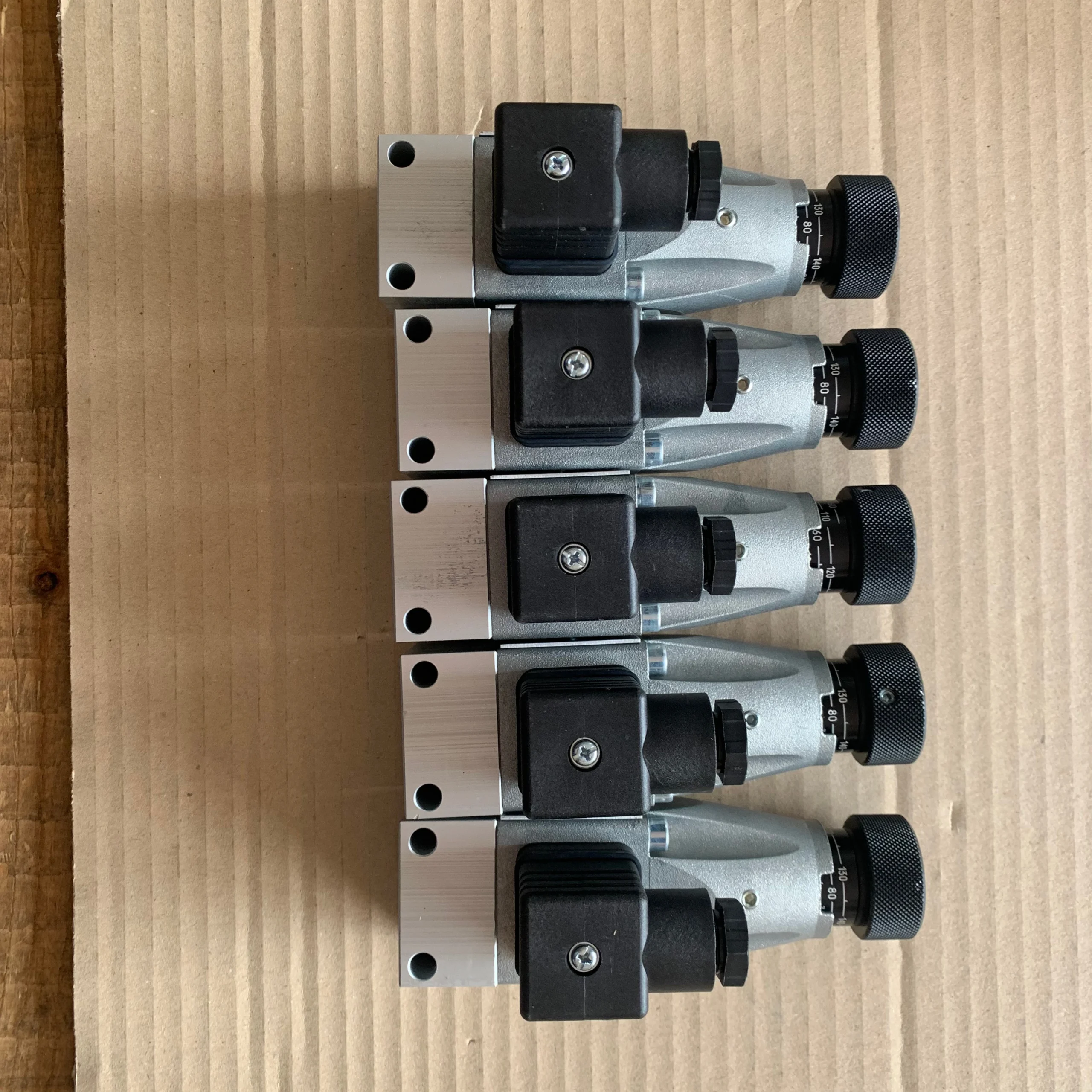


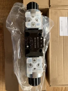
Hydraulic Solenoid Valve DS3-S1/11N-D24K1/CP Directional Control Hydraulic Valve DS3 DS5 DSE3 DSP7 MDS3
Diameter and flow rate: Nominal diameter 6 mm (corresponding to ISO 4401-03 standard mounting surface), maximum flow rate 100 L/min, suitable for medium and high pressure medium and small flow hydraulic systems.
Work pressure
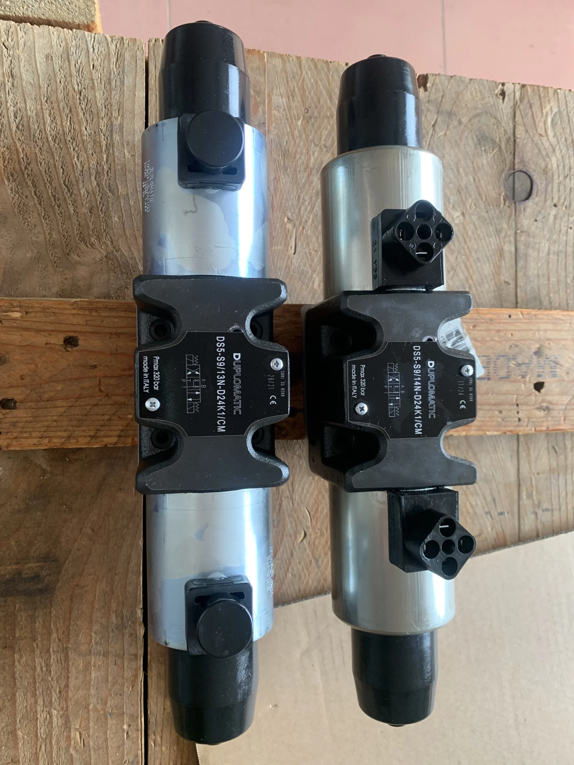
Oil port P/A/B: Continuous working pressure 350 bar (35 MPa), peak pressure 350 bar
Return oil port T: Back pressure ≤160 bar (DC type) or 140 bar (AC type).
Power supply and coil
Powered by 24V DC (D24), with a power of approximately 30W, featuring an LED status indicator light (K1), and having a protection grade of IP65.
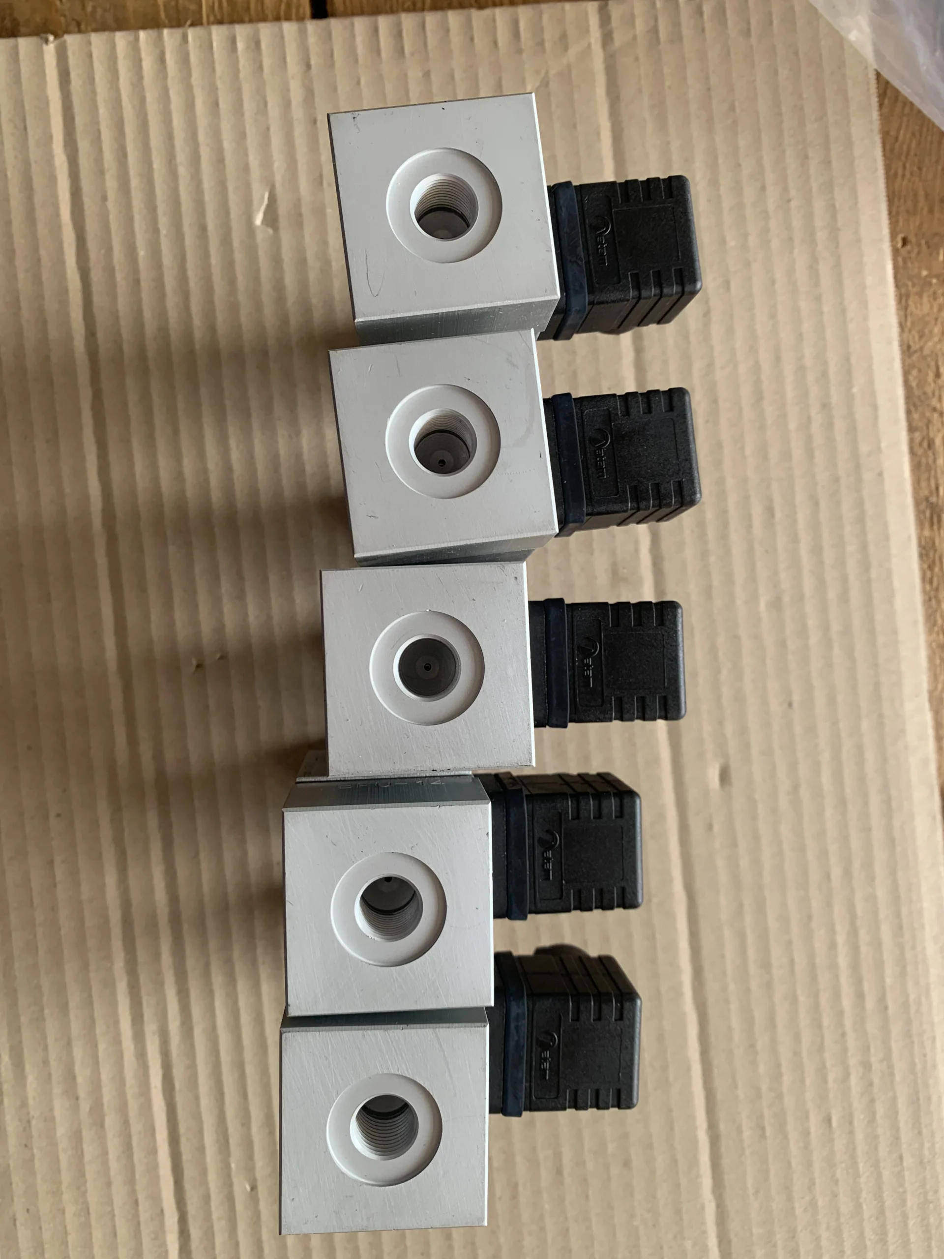
The coil is detachable and interchangeable, and supports 360° rotation installation to adapt to space limitations.
Position configuration: Three-position four-way (3-position four-way), spring centering design, valve core function is O-type (P/A/B/T ports are fully closed when in the middle position).
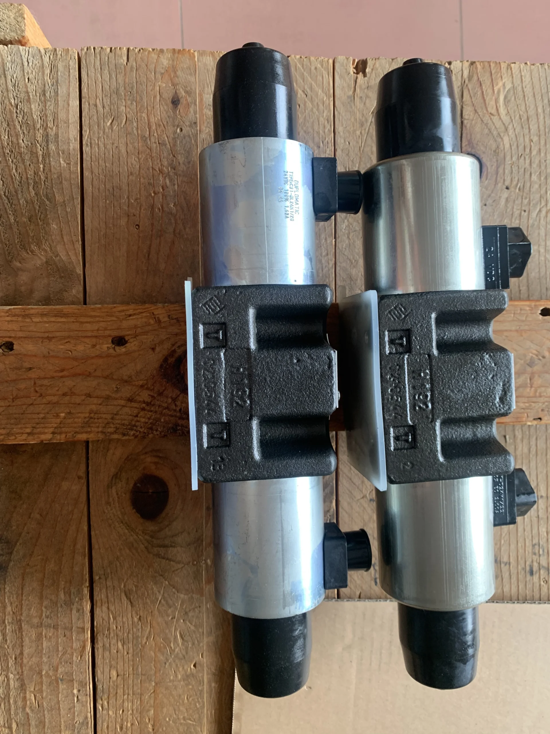
Structural form: Direct-acting spool valve structure, wet armature electromagnet (core oil-immersed for heat dissipation), high-strength cast iron valve body, internal flow channel optimization to reduce pressure loss.
Oil requirements
Applicable viscosity: 10-400 mm²/s (Recommended ISO VG 46)
Working oil temperature: -20℃ to 80℃. The cleanliness of the oil should reach ISO 4406:1999 grade 20/18/15 (NAS 10 grade).
Installation method: Plate installation, in compliance with ISO 4401-03 standard. Flatness of the installation surface ≤ 0.05mm, roughness ≤Ra 1.6 μm.Ii. Working Principle
This valve is a direct-acting electromagnetic directional control valve. It directly drives the displacement of the valve core through electromagnetic force to achieve direction control of the oil circuit. The specific working process is as follows:
Initial state: When power is cut off, the spring pushes the valve core to the middle position, the P/A/B/T ports are fully closed, the system maintains pressure and the actuator remains stationary.
Power-on action:
When one side of the electromagnet is energized, the electromagnetic force overcomes the spring force to push the valve core to move in the corresponding direction. The pressure oil (port P) flows to port A, and the oil at port B returns to the oil tank through port T, driving the actuator to move forward.
When the electromagnet on the other side is energized, the valve core moves in the opposite direction, and the pressure oil flows to port B, while oil returns to Port A, and the actuator moves in the opposite direction.
Characteristics of wet electromagnets: The core works when immersed in oil, reducing friction and wear, with high heat dissipation efficiency, and can adapt to frequent switching (recommended frequency ≤120 times per minute).
Manual emergency operation: Equipped with a push-type manual knob (CP), the valve core position can be manually switched in case of power failure or electronic control failure to ensure the emergency operation of the system.
Iii. Product Features and Advantages
High-voltage adaptation and reliability
The rated pressure of 350 bar can meet the requirements of heavy equipment. The wear-resistant valve core and cast iron valve body design enable its service life to reach over 5,000 hours in dusty working conditions.
Explosion-proof type is optional (ATEX II 2G/2D certified), suitable for flammable and explosive environments (such as petrochemical, mining).
High efficiency and energy-saving performance
The fully enclosed design of the valve core in the middle position reduces system leakage, and the standby power consumption is as low as 0.5W (only maintaining the coil current).
Wet electromagnets generate less heat, and the rise in system oil temperature is more than 10% lower than that of dry valves.
Control flexibility
Supports 0-10V or 4-20mA analog control (external amplifier required) to achieve stepless adjustment of valve core displacement.
The switching time is ≤30 ms (10%-90% step signal), and the response speed is superior to that of similar direct-acting valves.
Maintenance convenience
The modular structure supports the individual replacement of coil or valve core assemblies, standardizing seals and reducing maintenance costs by 30%.
The oil port is clearly marked, and the installation direction is not restricted. It can be installed horizontally or vertically.
Iv. Usage Functions and Purposes
Usage function:
Directional control: By switching the position of the valve core, the flow direction of the hydraulic oil is changed to drive the hydraulic cylinder or hydraulic motor to move in both forward and reverse directions.
Pressure protection: In coordination with the system relief valve, it limits the maximum working pressure to prevent equipment damage due to overload.
Emergency operation: The manual knob can force the valve core to switch in case of power failure to ensure the execution of critical actions.
Purpose:
Industrial automation: Mold closing for injection molding machines, feed for metalworking machines, and fixture control for automated production lines.
Construction machinery: excavator boom telescopic mechanism, loader bucket lifting mechanism, crane luffing mechanism.
Energy and Chemical Industry: Hydraulic systems for oil drilling RIGS, stirring drives for chemical reaction vessels.
V. Applicable Machines and Scenarios
Applicable machines
Small and medium-sized injection molding machines (clamping force ≤1500 tons), 5-10 ton hydraulic excavators, CNC bending machines.
Auxiliary hydraulic systems for underground tunneling equipment in mines and container gantry cranes in ports.
Applicable scenarios
High-pressure and low-flow systems, such as precision press-fitting in the processing of automotive parts.
In industrial sites with a lot of environmental dust or limited maintenance conditions, its anti-pollution properties can be utilized to reduce the failure rate.
Flammable and explosive environments that require explosion-proof certification, such as oil and gas extraction platforms and coal mine roadways.
Six. Similar models
Model of the same series
DS3-TA/11N: 2-position 3-way, spring return, suitable for simple direction control.
DS3-RK/11N: 3-position 4-way, mechanically positioned valve core, suitable for long-term pressure-holding systems that require maintaining the center position.
Similar alternative models
Direct-acting electromagnetic directional control valves (such as A series 6-way valves) : The structure and principle are the same, with a rated pressure of 350 bar and support for AC power supply.
Pilot-operated proportional directional control valves (such as XB series 10-bore valves) : They amplify the flow rate through the pilot stage and are suitable for systems with a flow rate of over 100 L/min.
DS3-S3/10N-A110K1 DS3-S1/10N-A110K1 DS3-S4/10N-D24K1 DS3-SA1/10N-A230K1 DS3-TB/10N-A230K1 DS3-RK/10N-D24K1 DS3-TB23/10N-D24K1
DS3-SB1/10N-A110K1 DS3-SB11/10N-D24K1 DS3-S2/10N-D12K1 DS3-S21/10N-D24K1 DS3-RK/10N-A230K1 DS3-S2/10N-A230K DS3-S2/10N-A24K1
DS3-S3/10N-A230K1 DS3-S1/10N-D24K1 DS3-S1/10N-D12K1 DS3-S4/10N-A110K1 DS3-S2/10N–D24K1 DS3-S3/10N-D24K1 DS3-S4/10N-D12K1
DS3-TB/10N-D110K1 DS3-TA/10N-D24K1 DS3-TB/10N-D12K1 DS3-RK/10N-D110K1 DS3-TA/10N-A230K1 DS3-SA2/10N-D24K1 DS3-S1/10N-D12K1
DS3-TB/10N-A110K1 DS3-RK/10N-A230K1 DS3-RK/10N-A110K1 DS3-SA2/10N-D12K1 DS3-RK/10N-D24K1 DS3-SA2/10N-A30K1 DS3-S1/10N-A230K1
DS5-S1/10N-D24K1 DS5-S4/10N-D12K1 DS5-TA/10N-D24K1 DS5-S3/10N-D24K1 DS5-S4/10N-D24K1 DS5-TA/10N-D12K1 DS5-TA/10N-A24K1
DS5-TA/10N-A110-50K1 DS5-TA/10N-A230K1 DS5-S1/10N-D12K1 DS5-S1/10N-A24-50K1 DS5-S1/10N-A110-50K1 . DS5-S1/10N-A230-50K1
DS5-SA2/10N-D12K1 DS5-SA2/12N-D24K1 DS5-RK/10N-D24K1 DS5-RK/10N-A110-50K1 DS5-S2/10N-D12K1 DS5-S2/10N-D24K1 DS5-S2/10N-A110K1
DS5-S2/10N-A230-50K1 DS5-S3/10N-D12K1 DS5-S3/10N-A110-50K1 DS5-S3/10N-A230-50K1 DS5-S4/10N-A110-50K1 DS5-S4/10N-A230-50K1
DS5-S6/10N-A110-50K1 DS5-SB1/11N-A110K1 DS5-TA23/10N-D24K1 DS5-RK/10N-A230-50K1 DS5-SB1/12N-D24K1 DS5-TB23/10N-D24K1
DS5-S1/10N-D24K1 DS5-S1/10N-A230K1 DS5-S2/10N-D24K1 DS5-S3/10N-D24K1 DS5-S4/10N-D24K1 DS5-S4/10N-A230K1 DS5-TA/10N-D24K1
DS5-TA/11N-A230K1 DS5-RK/10N-D24K1 DS5-RK/10N-A230K1 DS5-TB23/10N-A110-50K1 DS5-TA23/10N-A110-50K1 DS5-S11/12N-D24K1
DS5-S1/11N-D24K1 DS5-TA/11N-D24K1 DS5-S3/11N-D24K1 DS5-S6/11N-D24K1 DS5-TA02/11N-D12K1 DS5-S1/11N-D12K1 DS5-S11/11N-D24K1
DS5-S1/11N-A110K1 DS5-SA1/11N-D24K1 DS5-S3/10N-D24K1 DS5-TA/10N-D24K1 DS5-SB3/12N-D24K1 DS5-S3/11N-D12K1 DS5-S3/11N-A230K1
DS5-S7/11N-A230K1 DS5-TA23/11N-D24K1 DS5-S3/10N-D110K1 DS5-SB1/11N-D24K1 DS5-SB2/11N-D24K1 DS5-SA1/10N-A230K1 DS5-S1/11N-A230K1
DS5-S3/11N-A230K1 DS5-S4/11N-A110K1 DS5-TA/10N-A230K1 DS5-SA2/11N-D24K1 DS5-SA1/10N-D24K1 DS5-SB1/10N-D24K1 DS5-S7/10N-A110K1
DS5-SB1/11N-A230K1 DS5-SA2/11N-D12K1 DS5-S8/10N-A230K1 DS5-TB02/10N-D12K1 DS5-TA23/11N-A230K1 DS5-S1/11N-D24K1 DS5-S3/11N-D24K1
DS5-S4/12N-D24K1 DS5-TA/11N-D12K1 DS5-SA2/12N-D24K1 DS5-RK/11N-D24K1 DS5-S6/12N-D12K1 DS5-S1/12N-A230K1 DS5-S9/12N-D24K1
DS5-SB2/11N-D24K1 DS5-S20/12N-D12K1 DS5-RSA1/11N-A230K1 DS5-SB1/12N-D24K1 DS5-SB3/12N-D24K1 DS5-S3/12N-A230 DS5-TB/10N-A110K1
DSP7-S1/10N-D24K1 DSP7-S11/10N-II/D24K1 DSP7-S3/10N-II/D24K1 DSP7-S3/10N-IE/D24K1 DSP7-TA/10N-IE/D24K1 DSP7-TA/10N-IE/A230-50K1
DSP7-S1/10N-IE/A230-50K1 DSP7-S4/10N-CI-C/A110-50K1 DSP7-S1/10N-CI-C/A110-50K1 DSP7-TB/10N-II/D24K1 DSP7-SA1/10N-EI/D24K1
DSP7-12/10N/IE/AB10/D24K1 DSP7-S11/10N-IE/D24K1 DSP7-RK/20N-II/A110K1 DSP7-S12/20N-IE/AB10/D24K1 DSP7-S6/20N-II/A110/K1
DSP7-S2/20N-EE/D24K1
Vii. Precautions for Use
Oil and Fluid Management Specifications
Select hydraulic oil strictly in accordance with requirements and avoid mixing oils of different brands. It is recommended to change the hydraulic oil and clean the oil tank every 2,000 hours.
A ≥100 μm screen filter is installed at the oil suction port, and a 25 μm fine filter is added to the return oil line to prevent particles from wearing the valve core.
Installation and wiring requirements:
Use a torque wrench to tighten the installation bolts at the specified torque (such as 15-20 N · m) to ensure that the flatness of the installation surface meets the standard and prevent the valve body from deforming and causing leakage.
Signal cables should be laid separately from power cables, shielded wires should be used and reliably grounded to prevent electromagnetic interference from affecting control accuracy.
Debugging and operation monitoring
Before the initial start-up, manually check the flexibility of the valve core. Run it no-load for 5 minutes and then gradually load it to the rated pressure.
During operation, monitor the oil temperature (30-70℃ is the best), pressure (overpressure is strictly prohibited) and the temperature of the electromagnet (≤80℃). If any abnormality is detected, stop the machine immediately for inspection.
Safety operation suggestions
Before maintenance, the power source of the system must be cut off and the pressure released to prevent personal injury caused by high-pressure oil injection.
In safety-related applications (such as lifting equipment), mechanical locking devices need to be configured as redundant protection.
Long-term storage requirements
When the machine is out of service for a long time, the oil should be drained or anti-rust oil should be injected. The oil port should be sealed to prevent impurities from entering. The humidity of the storage environment should be no more than 70%.


