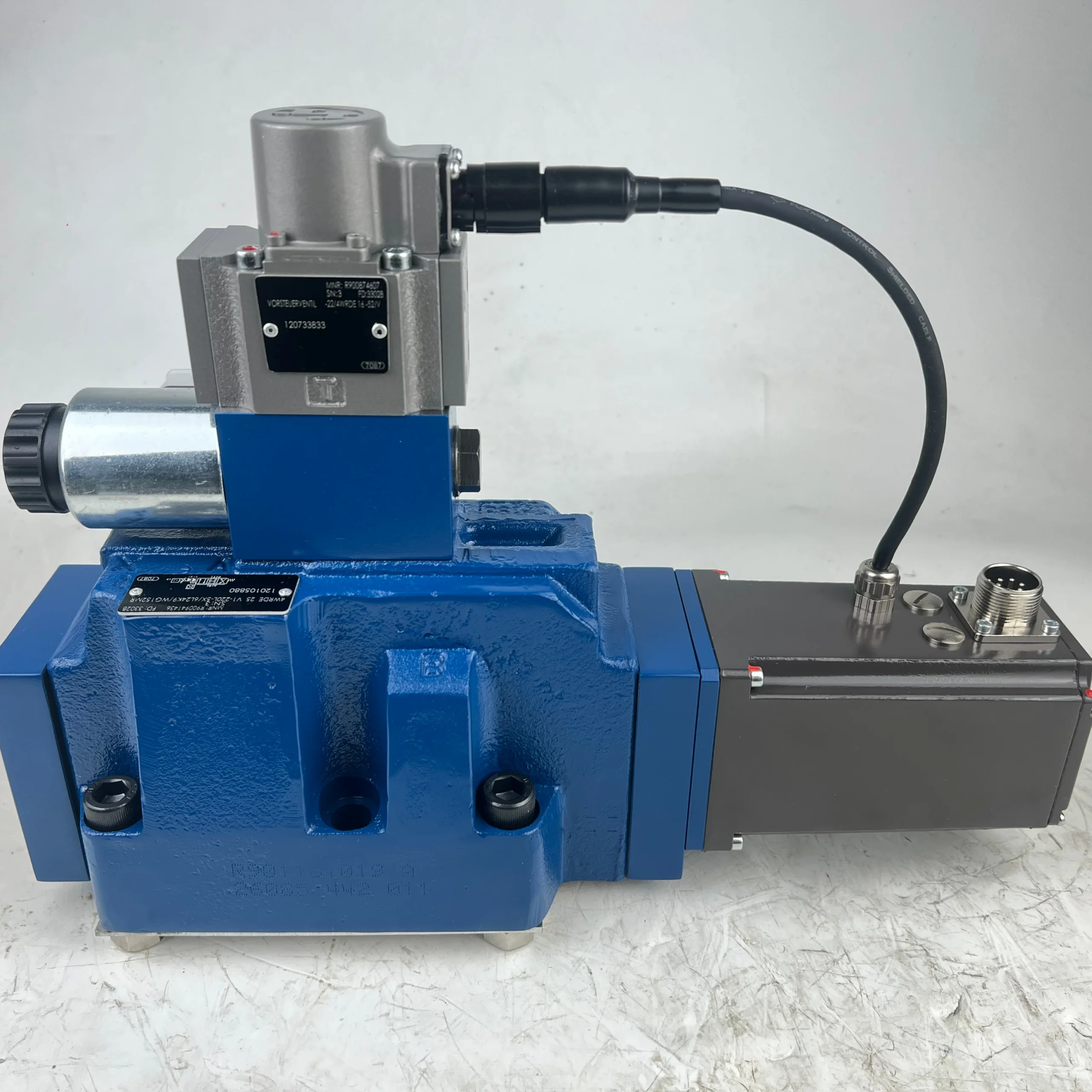


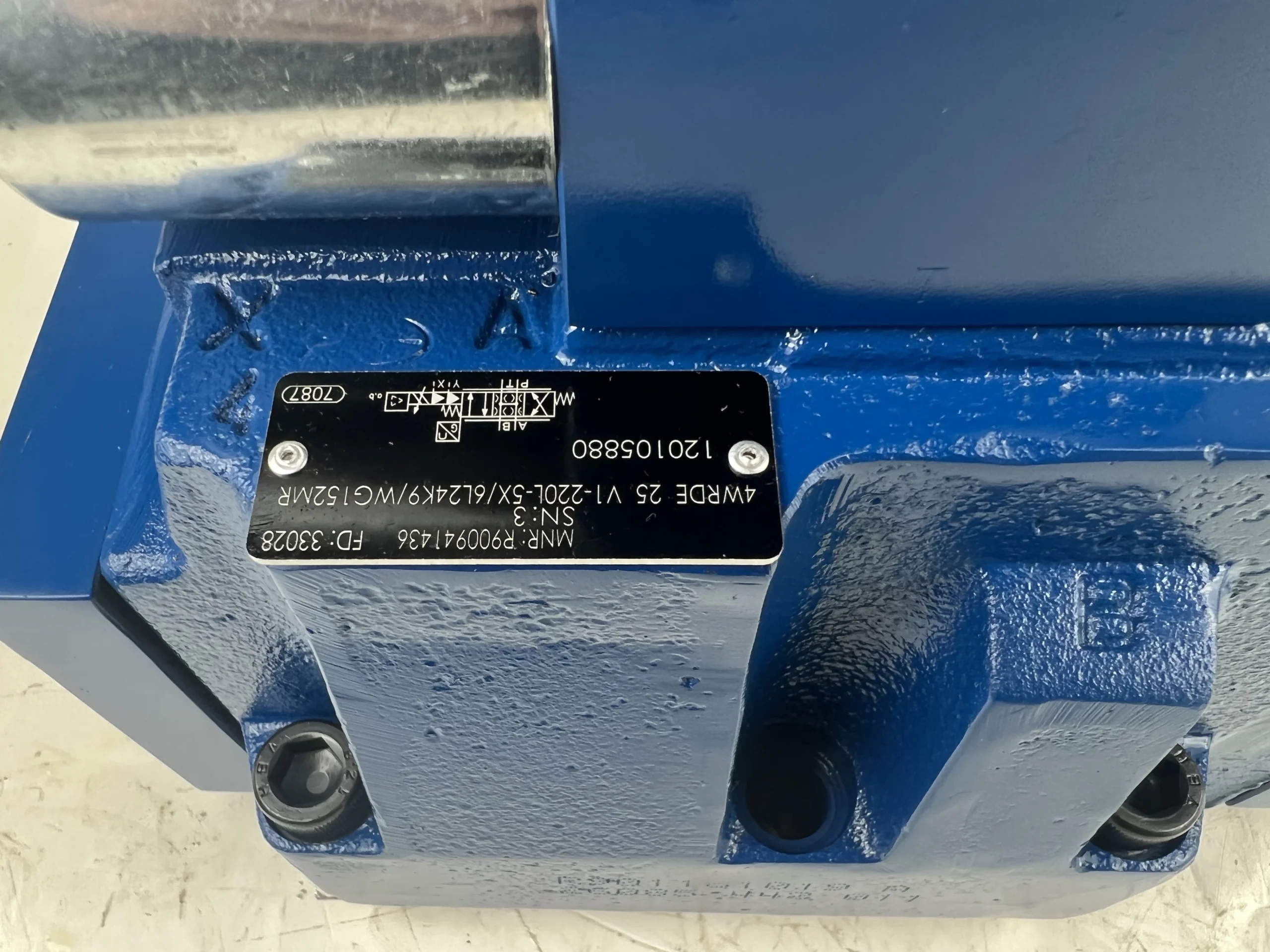
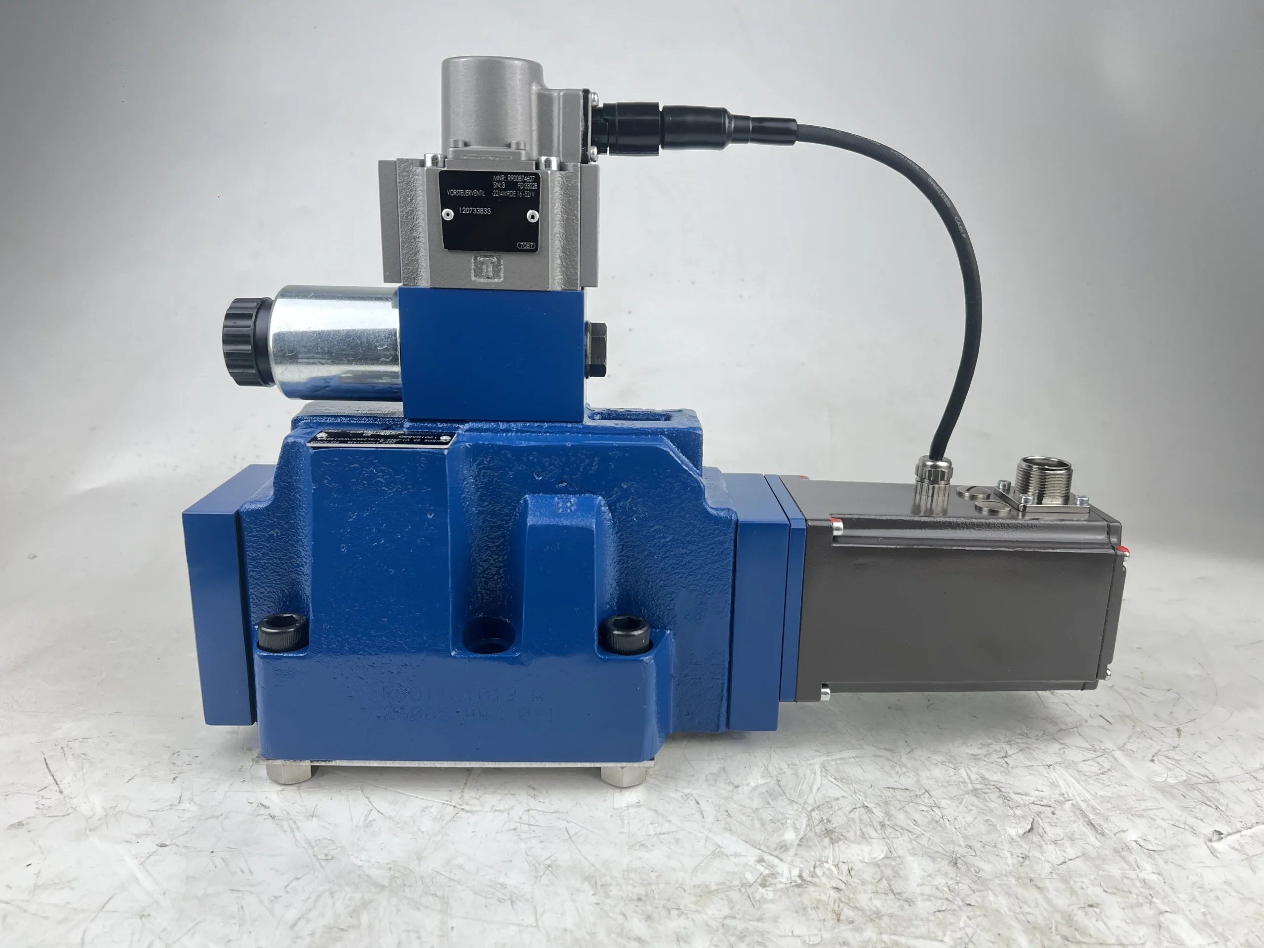


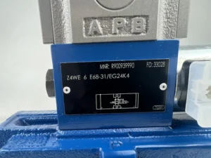
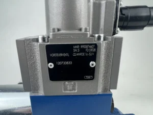
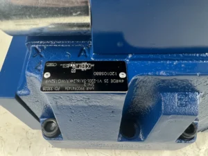
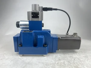
Hydraulic Proportional Directional 4WRDE 4WRDE10/16 4WRDE25 4WRDE27/32 Series 4WRDE 25 V1-220L-5X/6L24K9/WG152MR
Core performance parameters
•Valve type: Electro-hydraulic proportional directional flow valve (four-position four-way), featuring proportional flow regulation, directional control and pressure compensation functions. The control mode is electro-hydraulic proportional control + manual emergency operation, suitable for precise control requirements of medium and high-pressure high-flow hydraulic systems.
•Pressure rating: Rated working pressure 31.5 MPa (315 bar), maximum allowable pressure at the oil inlet 31.5 MPa, back pressure at the oil return port ≤2.5 MPa. The pressure loss is ≤1.2 MPa (at rated flow), and it can withstand a short-term peak pressure of 35 MPa (duration ≤5 seconds).
•Flow parameters: Rated flow rate 220L /min (corresponding to the model marked “220L”), maximum through flow rate 250 L/min (short-term continuous ≤10 minutes); Flow control accuracy is ±1% (at rated flow), proportional control range is 5%-100% (11-220 L/min), and flow repeatability error is ≤0.5%.
•Control parameters: Control voltage 24 V DC (corresponding to the model marked “24K9”), control current 400-800 mA; The adjustable gain range of the proportional amplifier is 5-20 V/(L/min), the response time is ≤50 ms (when the flow rate increases from 10% to 90%), and there is no overshoot in the step response.
•Core material The main valve core is made of alloy structural steel (2Cr13, quenched treatment, surface hardness HRC50-55, surface roughness Ra0.4 μm), the valve seat is stainless steel (304, ground sealing surface, flatness ≤ 0.005mm), and the valve body is forged carbon steel (45#, quenched and tempered, tensile strength ≥600 MPa). The sealing parts are made of fluororubber (with a temperature resistance range of -20℃ to 120℃).
•Connection specifications: The connection methods for the oil inlet (P port), return oil port (T port), and working oil port (A/B port) are threaded connections, compatible with metric threads M42×2 (P/T port) and M36×2 (A/B port). The installation method is plate installation, compatible with the ISO 7368 standard installation surface. The installation hole diameter is Φ 18mm, and the installation center distance is 120× 80mm.
•Cleanliness standard: The oil cleanliness is required to reach ISO 4406 16/13 grade (NAS 7 grade). A 10 μm high-pressure filter (filtration accuracy 10 μm, rated pressure ≥40 MPa, dirt-holding capacity ≥50 g) should be installed at the front end of the oil inlet, and a 20 μm filter should be added at the return oil inlet.
•Environmental parameters: Operating environment temperature -20℃ to 80℃, relative humidity ≤95% (no condensation); It can adapt to vibration (vibration acceleration ≤15 m/s², frequency 10-1000 Hz), oil contamination working conditions, with a protection level of IP65 (for the electromagnet part), and avoid long-term exposure to dust concentration > 10 mg/m³ or corrosive gas environments.
Ii. Working Principle
This valve is an electro-hydraulic proportional directional flow valve. Through the core mechanism of “proportional conversion of electrical signals – hydraulic signals – precise regulation of the flow direction of the main valve – feedback closed-loop correction”, it realizes the proportional control of the flow and direction of the hydraulic system. The specific working process is as follows
1. Control signal reception and conversion
The 0-10V or 4-20mA electrical signal output by the control system (compatible with the proportional amplifier) is connected to the proportional amplifier integrated in the valve body. The amplifier converts the weak current signal into a 400-800mA current signal that can drive the proportional electromagnet. The intensity of the current signal is proportional to the input electrical signal, thereby controlling the suction force of the proportional electromagnet and achieving a linear conversion of “electrical signal intensity – electromagnet thrust”.
2. Main valve regulation and flow direction control
•Direction control :The valve body is equipped with two proportional electromagnets (corresponding to the A/B working oil ports). When the electromagnet on the left is energized, the thrust pushes the pilot valve core to move, controlling the pressure oil to enter the left cavity of the main valve core, pushing the main valve core to move to the right, connecting the oil inlet (P port) with the A port and the B port with the return oil port (T port), allowing the hydraulic oil to enter the rod-free cavity of the actuator and extending the driving mechanism. When the electromagnet on the right side is energized, the main valve core moves to the left, connecting port P with port B and Port A with port T, and the actuator retracts. When the electromagnet is de-energized, the main valve core returns to the neutral position under the action of the reset spring, and the P port and the A/B port are disconnected, achieving pressure retention.
•Flow control: The displacement of the main valve core is proportional to the thrust of the proportional electromagnet (the greater the current, the greater the displacement). The opening degree of the throttling window on the main valve core changes linearly with the displacement. The flow through the window is proportional to the opening degree (under the action of the pressure compensation valve, the flow is not affected by the load pressure). When the input electrical signal changes linearly, the displacement of the main valve core changes linearly, the opening of the throttling window is adjusted linearly, and the output flow rate changes linearly accordingly, achieving proportional control of the flow rate.
Iii. Product Features and Advantages
1. Precise proportion control with high adjustment accuracy
Adopting the “electro-hydraulic proportional + displacement feedback closed-loop” design, the flow control accuracy reaches ±1%, and the proportional regulation range is 5%-100% (11-220 L/min), which can achieve stepless adjustment of the actuator speed. The response time for direction switching is ≤50 ms, and the flow step response has no overshoot. It is suitable for scenarios with high requirements for the smoothness and accuracy of actions (such as mold locking of injection molding machines and compound actions of excavators).
With a rated pressure of 31.5 MPa, a rated flow rate of 220 L/min, and a maximum flow rate of 250 L/min, it can meet the control requirements of medium and high-pressure high-flow hydraulic systems. The pressure compensation valve ensures that when the load pressure varies within the range of 5 to 31.5 MPa, the flow fluctuation rate is no more than 2%, eliminating the need for additional flow control valves and simplifying the system structure.
The proportional electromagnet adopts highly efficient magnetic conductive materials, with A thrust density of 15 N/A. Combined with the optimized design of the pilot stage, the response time of the main valve core is ≤50 ms, which is 30% higher than that of ordinary proportional valves. The feedback frequency of the displacement sensor reaches 1 kHz, which can correct the displacement deviation of the valve core in real time. Even when the load suddenly changes (such as when the excavator suddenly encounters an obstruction), it can still maintain a stable flow rate and avoid action shock.
The main valve core is quenched with 2Cr13, with a surface roughness of Ra0.4 μm. It is combined with a 304 stainless steel ground valve seat, with a wear coefficient as low as 0.001. Fluororubber seals have excellent oil and temperature resistance, and their trouble-free operating life under rated conditions can reach 12,000 hours. The electromagnet has a protection grade of IP65, which can adapt to damp and dusty industrial environments. Its service life is 40% longer than that of ordinary proportional valves.
It integrates a proportional amplifier and displacement sensor, eliminating the need for an external control module. Its volume is reduced by 40% compared to the split design, saving installation space for the hydraulic station. The modular structure enables vulnerable parts such as electromagnets and seals to be disassembled and replaced separately. During maintenance, there is no need to disassemble the main valve body, and the time for replacing seals is ≤1.5 hours, reducing operation and maintenance costs.Iv. Usage Functions and Purposes
1. Core usage functions
•Proportional flow regulation: Linearly adjust the output flow (11-220 L/min) based on the input electrical signal to achieve stepless control of the speed of the actuator (hydraulic cylinder, hydraulic motor), and is suitable for scenarios with high requirements for speed accuracy (such as speed regulation of CNC hydraulic press pressing).
•Direction control: By switching the energized states of the left and right electromagnets, the on-off switching of the working oil port A/B is achieved, controlling the extension/retraction or forward/reverse rotation of the actuator. At the neutral position, the system pressure is maintained (leakage ≤ 0.5L /min).
•Pressure compensation and load adaptation: The built-in pressure compensation valve maintains a stable pressure difference between the oil inlet and the working oil inlet, ensuring that the flow rate remains constant when the load pressure changes. When the load exceeds the system pressure, the relief valve is used in conjunction to achieve overload protection and prevent damage to the valve body.
•Manual emergency operation: Equipped with a manual adjustment knob, when the electrical system malfunctions, the main valve core can be pushed by manually rotating the knob to achieve emergency action of the actuator and enhance the reliability of the system.
2. Main application fields
•Construction machinery: 50-80 ton crawler excavator boom/bucket control, 20-30 ton wheel loader lifting/flipping mechanism, large bulldozer blade lifting system, precise control suitable for compound actions.
•Industrial manufacturing equipment: Large injection molding machines (clamping force 1000-2000 tons) clamping/injection mechanisms, 500-1000 ton CNC hydraulic press pressing systems, metallurgical rolling mill pressing devices, ensuring processing accuracy and smooth movement.
•Metallurgical and mining equipment: Medium-sized rolling mill (rolling width 1000-2000mm) roll gap adjustment system, mine tunnel boring machine (diameter 2-3 meters) propulsion mechanism, flotation machine stirring mechanism for mineral processing equipment, suitable for heavy-load impact working conditions.
•Special equipment: Ship deck machinery (anchor winches, winches), yaw drive systems for large-scale wind power equipment, and hydraulic stations for aerospace component testing, suitable for high-precision and high-reliability control requirements.
V. Applicable Machines and Scenarios
1. Adapt to the core machine
•Construction machinery: 50-80 ton crawler excavators, 20-30 ton wheel loaders, and bulldozers of D60 and above models.
•Industrial equipment: 1000-2000 ton injection molding machines, 500-1000 ton CNC hydraulic presses, medium-sized rolling mills (rolling width 1000-2000 mm).
•Heavy industrial equipment: 2-3 meter diameter mine tunnel boring machines, large flotation machines (with a volume of 10-20 m³), ship anchoring machines (with a tensile force of ≥500 kN).
•Specialized equipment: Medium and high-pressure precision hydraulic station (pressure 31.5 MPa, flow 220 L/min), wind power yaw drive system, aerospace hydraulic test bench.
2. Typical application scenarios
•Excavator compound action operation: In the compound action of the 60-ton excavator boom and bucket arm, the valve receives the proportional signal from the control system, synchronously adjusting the boom lifting and lowering and the bucket arm extension and retraction flow. The flow control accuracy is ±1%, and the action coordination is improved by 25%, avoiding action jamming. It is suitable for rock excavation in mines and deep foundation pit operations in infrastructure construction.
•
Injection molding machine mold locking operation In the clamping system of a 1500-ton injection molding machine, the valve linearly adjusts the clamping flow rate according to the set curve (from 11 L/min to 220 L/min), and the clamping speed smoothly increases from 5 mm/s to 100 mm/s. The clamping force control accuracy is ±2%, ensuring that the molding accuracy of plastic parts is ≤±0.03 mm. Suitable for mass production of car bumpers and large household appliance shells.
•Hydraulic press pressing operation In the 800-ton CNC hydraulic press pressing system, the valve regulates the pressing flow rate (50-220 L/min) to achieve stepless adjustment of the pressing speed. The pressure compensation valve ensures that the flow rate fluctuation is ≤1.5% when the load rises from 100 tons to 800 tons, and the flatness error of the pressed parts is ≤ 0.02mm, which is suitable for the precision forming of aerospace aluminum alloy parts.
•Tunneling machine advancement operation In the propulsion system of a 2.5-meter diameter mine tunnel boring machine, the valve dynamically adjusts the propulsion flow rate (30-180 L/min) based on the feedback signal of the tunneling load. When the load increases, the flow rate is automatically reduced to increase the thrust; when the load decreases, the flow rate is increased to enhance efficiency. The propulsion speed is stably maintained at 50-300 mm/min, making it suitable for continuous tunneling operations.
Six. Similar models
1. Alternative models of the same series
•4WRDE 25 V1-160L-5X/6L24K9/WG152MR: The structure is consistent with the original model, with a rated flow rate of 160 L/min, a maximum flow rate of 180 L/min, a rated pressure of 31.5MPa, a control accuracy of ±1%, and fully compatible installation dimensions. It is suitable for medium flow and high pressure scenarios (such as 30-ton loaders and 800-ton injection molding machines).
•4WRDE 25 V1-280L-5X/6L24K9/WG152MR: The high-flow models of the same series have a rated flow rate of 280 L/min, a maximum flow rate of 320 L/min, a rated pressure of 31.5MPa, and a pressure loss of no more than 1.5MPa. They have the same structural form and are suitable for high-flow medium and high-pressure systems (such as 80-ton excavators and 1000-ton hydraulic presses).
2. Cross-series alternative models
•3DREP 25 P-220L/315YG24K4V: Electro-hydraulic proportional pressure and flow valve, with a rated flow rate of 220L/ min and a rated pressure of 31.5 MPa. It features both pressure and flow proportional control functions and is suitable for scenarios requiring coordinated pressure and flow control (such as the combined working conditions of pressure holding and pressing in hydraulic presses). Its cost is 30% higher than that of the original model.
•4WREE 25 E-220L-5X/6EG24K31/A1V: Electromagnetic proportional directional valve, rated flow 220 L/min, rated pressure 31.5MPa, adopts direct-acting electromagnetic control, response time ≤ 30ms, suitable for scenarios with extremely high response speed requirements (such as CNC precision processing equipment), cost 40% higher than the original model.
•4WRTE 25V-220L-5X /6L24K9/M: Proportional throttle valve, rated flow rate 220L /min, rated pressure 31.5MPa, only has flow proportional control function, simple structure and low cost (25% lower than the original model), suitable for scenarios that only require flow regulation (such as conveyor speed control).
Vii. Precautions for Use
1. Oil and fluid management norms
•It is mandatory to use L-HM 46 or L-HV 68 anti-wear hydraulic oil. Different grades and types of oil are strictly prohibited from being mixed. The first oil change cycle is 500 hours, and it should be changed every 1000 hours thereafter. Before the oil change, the pipelines and oil tank should be flushed with new oil (the flushing oil volume should be ≥ twice the system volume), and the cleanliness of the oil after flushing should reach ISO 4406 17/14 grade.
•When the pressure difference of the oil inlet filter exceeds 0.3 MPa, it should be replaced immediately. The moisture content (≤0.1%) and acid value (≤0.15 mgKOH/g) of the oil should be tested monthly. If they exceed the standards, dehydration or oil replacement is required. When the viscosity of the oil is lower than 20 mm²/s or higher than 400 mm²/s, the oil of the corresponding viscosity should be replaced to avoid affecting the accuracy of proportional control.
2. Installation and commissioning requirements
•When using plate installation, the installation surface must be flat (flatness ≤ 0.05mm /m), and the installation bolts should be tightened with a torque of 200 N·m to ensure good sealing and no leakage. The oil inlet, return oil port and working oil port should be connected according to the valve body markings. Reverse connection is strictly prohibited (reverse connection will cause the pressure compensation valve to fail and lead to system failure).
•When making electrical connections, it is necessary to ensure that the power supply voltage of the proportional amplifier is stable (24 V DC±5%), and the control signal cables adopt shielded wires (the grounding resistance of the shielding layer is ≤1 Ω) to avoid electromagnetic interference causing distortion of the control signal. The terminal blocks of the electromagnet need to be tightened and have good waterproof sealing to prevent oil and moisture from entering and causing a short circuit.
•Before debugging, manually operate the emergency knob to check whether the main valve core moves flexibly without jamming. During the power-on debugging, the control signal should be gradually increased from the minimum (0 V or 4 mA) to the maximum (10 V or 20 mA) to observe whether the flow change is linear. At the same time, monitor the valve core displacement feedback signal (deviation ≤0.01 mm). After the debugging is completed, lock the parameters of the proportional amplifier to prevent accidental modification.
3. Operation monitoring and maintenance
•During operation, real-time monitoring of the valve body temperature (normal ≤75℃, maximum ≤85℃), inlet and outlet pressures (P port ≤ 31.5MPa, T port ≤ 2.5MPa), and the stability of control signals is conducted. If a sudden temperature rise of ≥10℃, abnormal pressure fluctuations, or signal deviations exceeding ±5% are detected, the machine should be immediately shut down for inspection. Focus on checking for oil contamination, valve core jamming or displacement sensor failure.
•Regular maintenance should be carried out every 2000 hours: replace the seals and reset springs, check the wear on the surface of the main valve core (replace if the wear exceeds 0.02mm), and grind the sealing surface of the valve seat (when the flatness error exceeds 0.005mm). The proportional amplifier is calibrated every 1500 hours to ensure the accuracy of electrical signal-flow conversion.
•Maintenance should be carried out in an environment with a cleanliness level of ≥1000. Before assembling the parts, they should be cleaned with aviation kerosene and coated with hydraulic oil to prevent impurities from entering the valve body. When installing the displacement sensor, it is necessary to ensure that the coaxiality with the main valve core is ≤ 0.02mm to avoid mechanical deviation affecting the feedback accuracy.
4. Storage and protection Specifications
•When stored for a long time, all oil ports should be sealed with special metal plugs. Anti-rust oil should be injected into the valve body (the oil volume should be 90% of the valve body volume, and L-TSA 46 anti-rust turbine oil should be selected). It should be placed in a dry and well-ventilated area (humidity ≤60%, temperature 5-35℃). Manually operate the emergency knob once a month to prevent the valve core from getting stuck and the metal parts from rusting.
•After being idle for more than 8 months, before putting it into use, drain the anti-rust oil and flush the valve body with new oil three times (after each flush, introduce low-pressure oil to test the flexibility of the valve core). After installation, conduct no-load debugging, gradually load to the rated pressure and flow rate, and run continuously for 30 minutes without leakage, stable signal and meeting the flow accuracy standards before it can be put into formal use.


