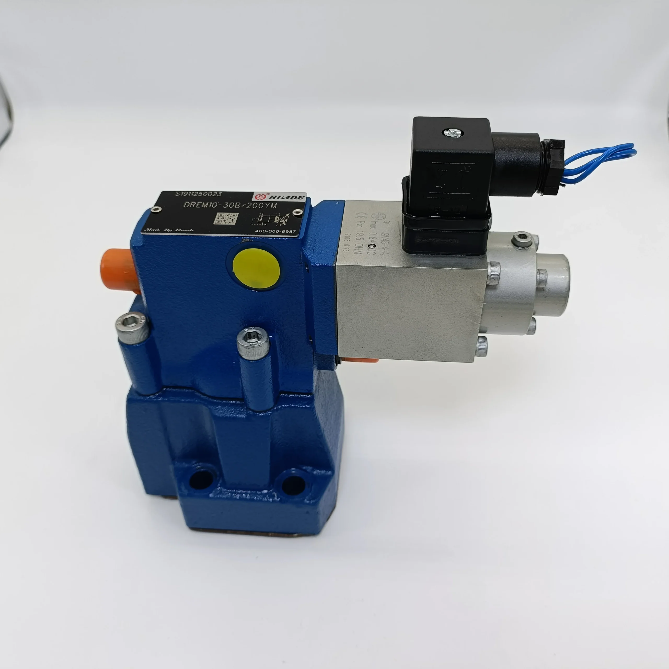


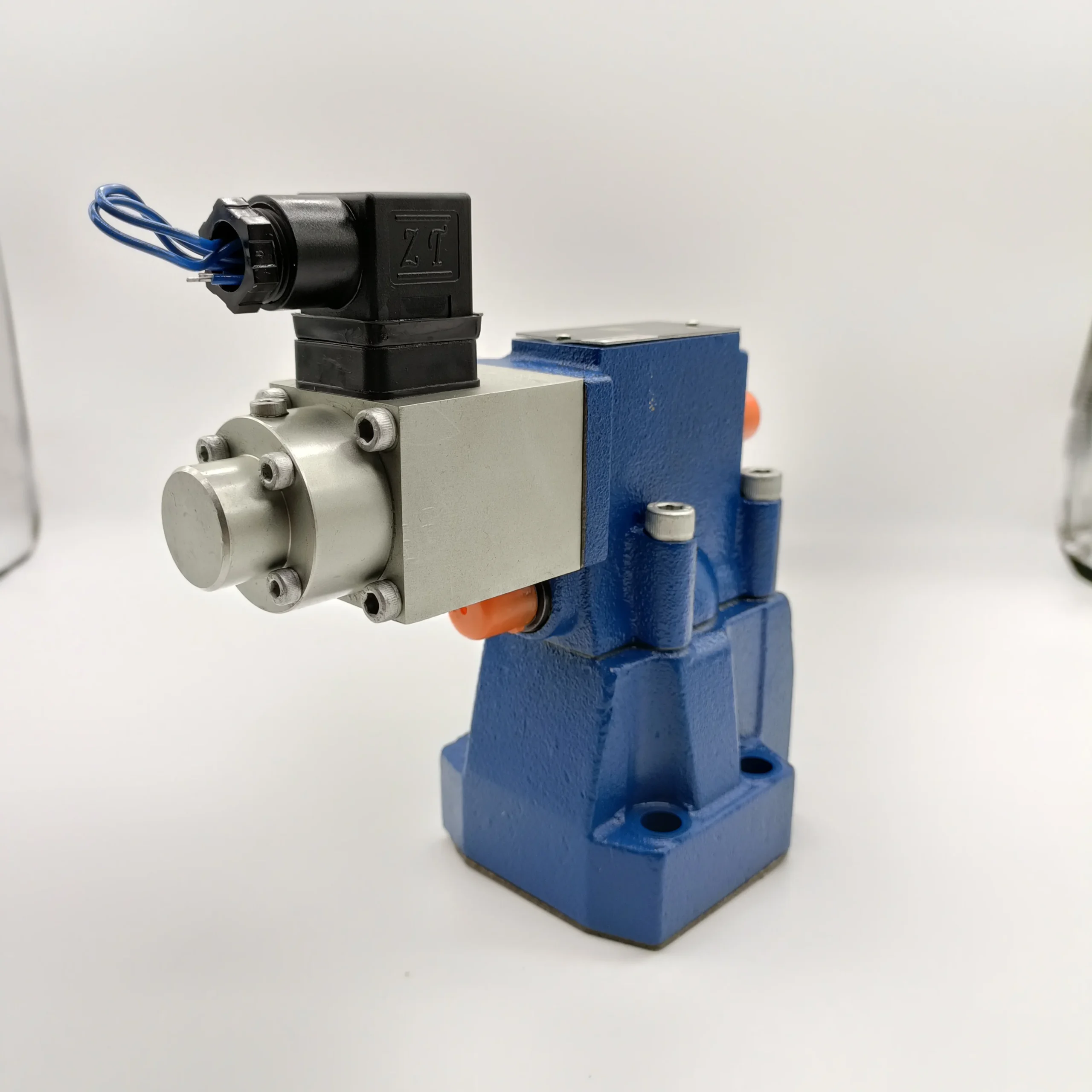

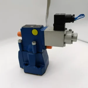
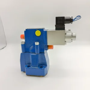

DRE DREM DREME DRE10 Series DREM20-6X/315YG24K4M Hydraulic Proportional Pressure Reducing Valve
1. Basic performance parameters- Valve type: Direct-acting proportional pressure reducing valve, integrated electro-hydraulic proportional control module and pressure feedback device, supports stepless pressure regulation, compatible with medium and high-pressure hydraulic control systems, and has overflow protection function
– Pressure and flow parameters: Rated working pressure 315 bar (” 315 “in the model corresponds to the core pressure parameter), adjustable pressure range 0-315 bar with stepless adjustment; Rated diameter: 20 mm, rated flow rate: 200 L/min (at 20℃), pressure regulation accuracy: ±1% FS, pressure fluctuation within the range of 50-200 L/min: ≤2 bar
– Control and response parameters: The proportional control signal is a 4-20mA DC current signal or a 0-10V DC voltage signal (compatible with dual signal input), with a signal resolution of ≤ 0.1mA. Step response time ≤50 ms (from 10% to 90% of the rated pressure), steady-state pressure deviation ≤1.5 bar, temperature drift ≤0.5% FS/℃
– Efficiency and power consumption parameters: Pressure loss under rated operating conditions ≤3 bar, volumetric efficiency ≥98%; The rated power consumption of the proportional electromagnet is ≤25 W, the standby power consumption is ≤5 W, and it has an automatic reset function in case of power failure (reset pressure ≤5 bar).
2. Structure and connection parameters
– Structural type: High-strength aluminum alloy valve body (tensile strength ≥280 MPa), surface anodic oxidation anti-corrosion treatment; It adopts a spool valve core structure, with the valve core treated by nitriding (hardness HV800-900), and is equipped with a pressure sensor to achieve closed-loop control. The sealing adopts a combined seal of fluororubber and polytetrafluoroethylene, with a static leakage rate of ≤0.3 mL/min. Integrated pilot control stage and main stage pressure reducing structure, with pressure compensation device
– Installation and connection specifications: Plate mounting (compatible with ISO 6264 standard mounting surface), the center distance of the mounting holes complies with the industry standard of 20mm bore valves; Oil port connection threads: The inlet P is G1½, the outlet A is G1½, and the return T is G1. The electrical interface is an M12×1 circular connector (with a waterproof rating of IP67), and the signal cables are compatible with shielded wires. The overall weight is approximately 3.2kg, and the external dimensions (length × width × height) ≈180×120× 100mm
– Protection grade: The valve body protection grade is IP65, and the electrical interface protection grade is IP67. It is suitable for dusty, water-splashed and medium to low vibration (vibration acceleration ≤ 15g) environments in industrial workshops, and supports vertical or horizontal installation
3. Medium and Environmental requirements
– Medium requirements: Compatible with L-HM 46/68 anti-wear hydraulic oil. L-HM 32 low pour point type can be selected for low-temperature working conditions. The allowable medium viscosity range is 10-400 mm²/s, and the optimal working viscosity is 15-50 mm²/s. The moisture content should be ≤0.03%, and the contamination degree of solid particles should reach ISO 4406 15/12 grade. Under harsh working conditions, it should be upgraded to 14/11 grade
– Environmental parameters: Working environment temperature -20℃ to 80℃, ideal working oil temperature 40-60℃; Storage temperature: -40℃ to 100℃, relative humidity: ≤95% (no condensation). Adapt to the rate of environmental temperature change ≤5℃/min, and avoid seal failure caused by sudden temperature changes
– Filtration requirements: A high-pressure filter with an accuracy of ≤10 μm must be installed at the oil inlet, and it is recommended to install a magnetic filter (with a filtration accuracy of ≤25 μm) at the oil return port. Before the system is put into operation for the first time, the pipelines need to be flushed to ensure that the oil cleanliness meets the standards
Ii. Working Principle
This valve is a direct-acting electro-hydraulic proportional pressure reducing valve. Its core achieves stepless regulation of the outlet pressure through the linear conversion of “electrical signal – force signal – pressure signal”, and is combined with pressure feedback closed-loop control to ensure regulation accuracy. The specific operating mechanism is as follows:
1. Core stress reduction and control mechanism
The 4-20mA (or 0-10V) proportional electrical signal output by the controller is connected to the proportional electromagnet. The electromagnet generates corresponding electromagnetic force based on the signal strength, pushing the pilot valve core to overcome the force of the reset spring and move, thereby changing the opening degree of the throttle port in the pilot stage. The control pressure output by the pilot stage acts on one end of the main valve core, forming a balance with the reset spring force at the other end of the main valve core. Under the action of the pressure difference, the main valve core moves along the axis, adjusting the opening degree of the main stage pressure reducing port. When the input electrical signal intensifies, the electromagnetic force increases, the opening degree of the pilot throttle port decreases, the control pressure rises, and the main valve core moves in the direction of reducing the opening degree of the pressure reducing port, causing the outlet pressure to increase accordingly. When the electrical signal weakens, the electromagnetic force decreases, the opening of the pilot throttle port increases, the control pressure drops, and the main valve core increases the opening of the pressure reducing port under the action of the reset spring, reducing the outlet pressure and achieving a linear correspondence between the outlet pressure and the electrical signal.
2. Feedback and protection mechanism
The integrated pressure sensor inside the valve collects the outlet pressure signal in real time, converts the pressure signal into an electrical signal and feeds it back to the controller, forming a closed-loop control loop. When the outlet pressure deviates from the set value due to load fluctuations, the deviation value between the feedback signal and the input signal drives the proportional electromagnet to adjust the output force, quickly correcting the opening degree of the main valve core, so that the outlet pressure returns to the set value, and the pressure regulation accuracy reaches ± 1%FS. The system also integrates an overflow protection function. When the outlet pressure exceeds the rated value of 315 bar, the built-in relief valve opens to unload, guiding the overpressurized oil back to the return oil port. When power is cut off, the proportional electromagnet loses power. The reset spring pushes the pilot valve core and the main valve core to reset, the pressure reducing port is fully opened, and the outlet pressure drops to the minimum (≤5 bar), avoiding system overload. The pressure compensation device can counteract the impact of inlet pressure fluctuations on outlet pressure. When the inlet pressure varies within the range of 10 to 315 bar, the outlet pressure fluctuation is ≤1% FS.
Iii. Product Features and Advantages
– Precise proportional regulation: It adopts closed-loop pressure feedback control, with a pressure regulation accuracy of ± 1%FS. The electrical signal has a strict linear relationship with the outlet pressure (linearity ≤ 0.5%FS), enabling precise setting of any pressure within the range of 0-315 bar. It is suitable for precision pressure control scenarios, such as pressure holding in injection molding machines and pressing in presses
– Fast response and stability: The step response time is ≤50 ms, which is 40% faster than that of traditional electromagnetic pressure reducing valves, and can quickly deal with sudden changes in load pressure. The pressure compensation device offsets the influence of inlet pressure fluctuations. When the inlet pressure changes, the outlet pressure fluctuation is ≤1 bar, ensuring the stability of the system pressure. The steady-state pressure deviation is ≤1.5 bar, reducing equipment vibration caused by pressure fluctuations
– High pressure resistance and long service life: The 315 bar rated pressure design is suitable for medium and high pressure systems. The valve core nitriding treatment and combined sealing design enhance wear resistance and corrosion resistance. The trouble-free operation life under rated conditions is ≥ 10,000 hours. The static leakage rate is ≤0.3 mL/min, which is 60% lower than that of ordinary pressure reducing valves, reducing energy waste
– Compatibility and convenience: Compatible with 4-20mA / 0-10V dual proportional signal input, it can be directly connected to PLC, DCS and other control systems to achieve automated remote control. The plate type installation is compatible with standard installation surfaces, and the electrical interface is IP67 protected, suitable for harsh environments. The modular design enables the replacement time of core components to be no more than 30 minutes, and maintenance can be completed on-site
Iv. Usage Functions and Purposes
1. Core usage functions
– Proportional pressure reduction control: The outlet pressure is steplessly adjusted from 0 to 315 bar through a 4-20 mA/0-10 V electrical signal. The signal corresponds linearly to the pressure, and the pressure value can be precisely set according to process requirements, such as adjusting the pressing pressure for different workpieces on a press and setting the holding pressure at different stages of an injection molding machine
– Pressure stability maintenance: Dual guarantee of pressure compensation and closed-loop feedback. When the inlet pressure fluctuates or the load changes, the outlet pressure quickly returns to the set value, with a fluctuation of ≤1 bar. It is suitable for scenarios with high requirements for pressure stability, such as precision processing and testing equipment
– Remote automatic control: It can be integrated with an automatic control system. By setting the pressure change curve through the program, it can achieve multi-stage automatic pressure switching, such as automatic pressure adjustment during the slow injection, fast injection, and pressurization stages of a die-casting machine, without the need for manual intervention
– Safety overflow protection: The built-in overflow valve automatically unloads when the outlet pressure exceeds 315 bar and automatically resets to a low-pressure state after power failure. This dual protection prevents system overload and reduces the risk of equipment damage
2. Main uses
As the core pressure control component of medium and high-pressure hydraulic systems, it is used to reduce the system inlet pressure to the set value and stably output it, providing precise pressure support for the actuating elements. It is widely compatible with equipment that requires automated and high-precision pressure control, and is a key component in fields such as construction machinery, industrial manufacturing, and precision testing. It is particularly suitable for hydraulic systems with multiple process stages and continuously adjustable pressure.
V. Applicable Machines and Scenarios
1. Adapt to the core machine
– Construction machinery: Hydraulic systems for 10-20 ton excavator boom/bucket arm, lifting mechanisms for small and medium-sized loaders, pressure regulating systems for hydraulic breakers, and pressure control circuits for luffing mechanisms of truck cranes
– Industrial machinery: 500-1000 ton press pressing system, 200-500 ton injection molding machine pressure holding circuit, die-casting machine injection pressure control system, heavy-duty machine tool hydraulic chuck pressure regulation, precision hydraulic test bench
– Special equipment: Pressure regulating systems for metallurgical equipment rolls, testing equipment for aerospace components, pressure pre-regulation for hydraulic servo control systems, pressure stabilizing devices for Marine hydraulic systems
2. Typical application scenarios
– Precision press pressing scenario: Equipped with a 630-ton precision press, the valve is controlled by a 4-20 mA signal output from the PLC. When pressing aluminum alloy workpieces, the pressure is set at 180 bar, and when pressing steel workpieces, it automatically rises to 250 bar. The pressure regulation response time is ≤40 ms, and the dimensional accuracy error of the workpiece is ≤0.05 mm. During the pressure stabilization stage, the fluctuation was no more than 0.8 bar, and the qualification rate of a single batch of workpieces increased to 99.5%
– Multi-stage pressure holding scenario for injection molding machines: Compatible with 300-ton injection molding machines, the pressure is set at 120 bar through 0-10V signals during the injection molding stage. It rises to 150 bar in the initial stage of pressure holding, drops to 100 bar in the middle stage of pressure holding, and then drops to 80 bar in the later stage of pressure holding. The pressure switching response time for each stage is ≤50 ms. When the pressure fluctuation is ≤1 bar, the shrinkage rate of plastic products is reduced by 60%, and the qualified rate of finished products is increased by 20%
– Hydraulic test bench test scenario: It is used for the pressure resistance test bench of hydraulic components. Through program control of electrical signal output, it can continuously increase the pressure from 0 to 315 bar (the increase rate is adjustable from 0 to 10 bar/s), with a pressure measurement accuracy of ±0.5%. It can automatically complete the pressure resistance curve test of components. During the testing process, the pressure fluctuation is ≤0.5 bar, and the repeatability error of the test data is ≤1%
Six. Similar models
1. Models with different diameters in the same series
-DREM16-6X /315YG24K4M: Rated diameter 16mm, rated flow 150 L/min, rated pressure 315 bar, suitable for medium and small-sized hydraulic systems, such as 300-500 ton presses, small injection molding machines, etc. Weight approximately 2.5kg, volume reduced by 20% compared to the original model
-DREM25-6X /315YG24K4M: Rated diameter 25mm, rated flow rate 300L /min, rated pressure 315 bar, suitable for large hydraulic systems such as 1000-1500-ton presses and large die-casting machines, with a 50% improvement in power compatibility, weight approximately 4.8kg
-DREM10-6X /315YG24K4M: Rated diameter 10mm, rated flow rate 80L /min, rated pressure 315 bar, suitable for small precision equipment such as hydraulic chucks and small test benches, weighing only 1.8kg, with a more compact structure
2. Models with the same diameter but different functions
-DREM20-6X /250YG24K4M: Low-pressure rated type, with a rated pressure of 250 bar, suitable for medium and low-pressure systems, such as small and medium-sized loaders, light presses, etc. The cost is 15% lower than the original model, and the pressure regulation accuracy is consistent
-DREM20-6X /315YG12K4M: Low-voltage control type, compatible with 12V DC control signals, suitable for vehicle-mounted hydraulic systems, small mobile devices, etc. Electrical power consumption is reduced by 30%, and the protection level remains IP67
-DREM20-6X /315YG24K4H: Equipped with analog feedback, it features a pressure signal output function (4-20mA), enabling closed-loop pressure monitoring. It is compatible with high-precision testing equipment and intelligent hydraulic systems, but its cost is 25% higher than that of the original model
R901299774 DREE10-6X/100YG24K31A1V
R901269802 DREE10-6X/100YMG24K31A1V
R901273234 DREE10-6X/200YG24K31A1M
R901278309 DREE10-6X/315YMG24K31A1M
R901299828 DREE20-6X/100YG24K31A1V
R901277135 DREM10-6X/100YG24K4M
R901277137 DREM10-6X/200YG24K4M
R901277145 DREM20-6X/200YG24K4M
R901277148 DREM20-6X/315YG24K4M
R901289453 DREME10-6X/200YG24K31A1M
R901289455 DREME10-6X/200YMG24K31A1V
R901289457 DREME10-6X/315YG24K31A1M
R900915975 DREM10-5X/50YG24K4M
R901038327 DREM10-5X/50YMG24K4V
R900959045 DREM10-5X/50YMG24K4M
R900766187 DREM10-5X/100YG24K4V
R900915969 DREM10-5X/100YG24K4M
R900964831 DREM10-5X/100YMG24K4V
R900940764 DREM10-5X/100YMG24K4M
R900726891 DREM10-5X/200YG24K4V
R900915972 DREM10-5X/200YG24K4M
R900955652 DREM10-5X/200YMG24K4V
R900915973 DREM10-5X/200YMG24K4M
R900924796 DREM10-5X/315YG24K4V
R900915974 DREM10-5X/315YG24K4M
R900968463 DREM10-5X/315YMG24K4V
R900907850 DREM10-5X/315YMG24K4M
R900929073 DREME10-5X/50YG24K31M
R901007766 DREME10-5X/50YMG24K31V
R901026612 DREME10-5X/100YG24K31V
R900920814 DREME10-5X/100YG24K31M
R900248507 DREME10-5X/100YMG24K31M
R900245560 DREME10-5X/200YG24K31V
R900925066 DREME10-5X/200YG24K31M
R900935959 DREME10-5X/200YMG24K31M
R900772417 DREME10-5X/315YG24K31V
R900927827 DREME10-5X/315YG24K31M
R900949908 DREME10-5X/315YMG24K31M
R900916194 ZDRE 10 VP1-1X/315XLMG24NK4M
R900925066 DREME 10-5X/200YG24K31M
R900925013 3DREPE 6 B-2X/45EG24N9K31/A1V
R900924796 DREM 10-5X/315YG24K4V
R900924326 DREME 20-5X/315YG24K31M
R900923602 ZDRE 10 VP2-1X/315XYMG24NK4M
R900923432 DREE 10-5X/200YMG24NK31M
R900923303 ZDREE 10 VP2-1X/200XYMG24NK31M
R900923187 DREM 20-5X/315YG24K4M
R900923017 ZDREE 10 VP2-1X/200XLMG24NK31M
R900922925 DRE 20-5X/315YG24K4M
R900921799 ZDREE 10 VP2-1X/100XLMG24K31M
R900921798 ZDREE 10 VP2-1X/100XLMG24NK31M
R900920814 DREME 10-5X/100YG24K31M
R900920580 DREE 10-5X/100YG24NK31M
R900919360 DREME 20-5X/100YMG24K31M
R900918272 DREME 20-5X/200YMG24K31M
R900917728 DRE 10-5X/200YG24K4M
R900917218 3DREP 6 B-1X/25A24N9K4M
R900916266 DRE 20-5X/200YG24K4M
R900916199 DRE 20-5X/315YMG24K4M
R900916198 DRE 20-5X/100YG24K4M
R900916197 DRE 10-5X/200YG24NK4M
R900916196 DRE 10-5X/315YMG24K4M
R900916195 DRE 6-1X/50MG24NK4M
R900915982 DREM 20-5X/50YMG24K4M
R900915981 DREM 20-5X/315YMG24K4M
R900915979 DREM 20-5X/200YG24K4M
R900915977 DREM 20-5X/200YG24NK4M
R900915975 DREM 10-5X/50YG24K4M
R900915974 DREM 10-5X/315YG24K4M
R900915973 DREM 10-5X/200YMG24K4M
R900915972 DREM 10-5X/200YG24K4M
R900915971 DREM 10-5X/100YMG24NK4M
R900915969 DREM 10-5X/100YG24K4M
Vii. Precautions for Use
Installation and commissioning
When installing, it is necessary to confirm the direction of the oil ports: the oil inlet P is connected to the high-pressure oil of the system, the oil outlet A is connected to the actuator, and the oil return T is connected to the oil tank. Reverse connection is strictly prohibited to cause damage to the valve components. When installing in a plate type, the sealing gasket should be made of high-pressure resistant fluororubber material, and the pre-tightening torque of the installation bolts should be ≥25 N·m to prevent pressure leakage
Electrical connections must use shielded cables to prevent electromagnetic interference from affecting the proportional signal. The electrical interfaces need to be tightened and properly treated for waterproofing to ensure an IP67 protection level. Before wiring, it is necessary to confirm the control voltage and signal type (4-20mA / 0-10V) to avoid incorrect connection which may cause the electromagnet to burn out
Before the first commissioning, the pipeline needs to be flushed to ensure that the oil cleanliness meets the standards (ISO 4406 15/12 grade). First, pass low-pressure oil (≤50 bar) to check if the seal is leaking. Then, connect the control signal and gradually increase the pressure from the minimum pressure (0 bar) to the rated pressure. Calibrate the linear relationship between the pressure and the signal (it is recommended to calibrate every 50 bar).
The installation position of the valve components should be far away from high-temperature heat sources (such as engine exhaust pipes). When the ambient temperature exceeds 45℃, a heat dissipation device should be installed. Avoid installing in locations with intense vibration. If necessary, add shock-absorbing pads to prevent false alarms from the pressure sensor caused by vibration
2. Operation and Maintenance
During operation, key parameters need to be monitored in real time: outlet pressure (fluctuation ≤1 bar), valve body temperature (normal ≤75℃, maximum ≤85℃), and control signal stability. In industrial scenarios, inspections should be conducted every 8 hours, and in construction machinery, every 4 hours. If pressure fluctuations exceed 2 bar, temperature rises sharply by more than 10℃, or abnormal signals occur, the machine should be stopped immediately for investigation
– Regular maintenance cycle: Under normal operating conditions, replace the hydraulic oil and oil inlet filter every 1,500 hours. Replace every 800 hours under harsh working conditions (such as in mining and metallurgy). Disassemble and inspect every 6,000 hours. Replacement is required when the valve core wear is ≥ 0.02mm and the sealing parts age. Calibrate the pressure sensor and linearity every 1000 hours to ensure the adjustment accuracy
It is strictly prohibited to operate when the oil cleanliness does not meet the standard (as it may cause the valve core to get stuck). Long-term operation with a pressure exceeding 315 bar is prohibited (single overload ≤5 seconds). When adjusting the pressure, the control signal should be changed slowly (at a rate of ≤5 bar/s) to avoid pressure shock. Before the system is shut down, the pressure should be reduced to ≤5 bar, and then the control signal and oil source should be cut off
3. Storage and Protection
When stored for a long time (more than 30 days), seal all oil ports with special plugs, inject special anti-rust oil (about 50 mL) into the valve cavity, and cover the electrical interfaces with waterproof and dustproof caps. Store in a dry and well-ventilated warehouse with a temperature ranging from 0 to 40℃ and a humidity of no more than 60%. Avoid direct sunlight, heavy object compression and oil contamination. Check the sealing condition once a month
Before being put into use after being idle for more than six months, the valve should be flushed with clean hydraulic oil