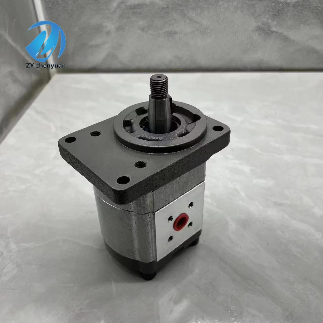


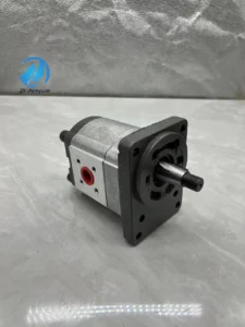

0510615326 AZPF-11-016LCP20MB-S0007 Hydraulic Gear Pump AZPW AZPB AZPS AZPN AZPG AZPF 0510 High Pressure Hydraulic Pump
Core performance parameters
– Pump type: External meshing fixed displacement gear pump, left rotation direction, single suction and single discharge oil structure (P oil intake, T oil return), suitable for medium and low pressure hydraulic systems, providing a stable hydraulic source for small and medium-sized actuators.
– Displacement and pressure parameters: Rated displacement 16 mL/r; Rated working pressure: 20 MPa, maximum allowable pressure: 25 MPa (short-term ≤10 seconds); The rated speed is 1500 r/min, the maximum speed is 2000 r/min (short-term ≤5 minutes), and the minimum stable speed is 100 r/min.
– Flow and efficiency parameters: Rated flow at rated speed is 24 L/min, and the flow fluctuation rate is ≤3%. Volumetric efficiency ≥90%, total efficiency ≥82%; The imported vacuum degree is ≤0.025 MPa (at rated speed).
– Operating characteristics: Continuous operating oil temperature ≤80℃, noise value under rated working conditions ≤78 dB (measured at 1 meter); The fault-free operating life under rated conditions is ≥ 8,000 hours.
2. Structure and connection parameters
– Structural type: External meshing involute gear structure, integrated cast iron pump body, alloy steel gear pair, needle roller bearing, skeleton oil seal and built-in safety valve; Axial clearance compensation devices are adopted to reduce leakage under high pressure. The pump body is equipped with an installation flange, simplifying the fixed layout.
– Core material: The driving/driven gears are made of chromium-molybdenum alloy steel (quenched and tempered, hardness HRC58-62); The pump body is made of alloy cast iron QT500-7 (aged treatment, hardness HB260-300). The bearing is a needle roller bearing (material GCr15, hardness HRC60-64). The seal is a combination of oil-resistant nitrile rubber and polytetrafluoroethylene (with a temperature resistance of ≤100℃).
– Connection specifications: The oil suction port (P) is of G3/4″ thread, and the oil return port (T) is of G1/2″ thread. The drive shaft is connected by a flat key (specification 12×30). The center distance of the flange bolts is 120×80 mm. The weight of the pump body is approximately 18 kg, and its external dimensions (length × width × height) ≈320×220×180 mm.
3. Medium and Environmental requirements
– Medium requirements: L-HM 46 anti-wear hydraulic oil is suitable for normal temperature. L-HM 32 is selected for low-temperature environment (below -10℃). The allowable viscosity of the medium is 10-300 mm²/s, and the moisture content is ≤0.03%. It is strictly prohibited to use media containing solid particles (particle size > 10 μm) or corrosive media.
– Cleanliness standard: The oil cleanliness should reach ISO 4406 17/14 grade. A 10 μm filter should be placed in front of the oil suction port. The filter should be replaced immediately when the pressure difference of the filter is greater than 0.05 MPa.
– Environmental parameters: Operating environment temperature -20℃ to 85℃, relative humidity ≤95% (short-term condensation is allowed); With a protection grade of IP54, it is suitable for small and medium-sized construction machinery, industrial hydraulic stations, agricultural machinery and other scenarios.Ii. Working Principle
This pump is an external meshing quantitative gear pump. Its core achieves stable hydraulic energy output through the mechanism of “gear meshing volume change – alternating suction and discharge of oil – pressure compensation seal”. The specific process is as follows:
1. Oil absorption process
The drive shaft rotates the driving gear, and the meshing of the driving gear drives the driven gear to rotate in the opposite direction. When the meshing teeth of the two gears on the suction port (P port) side gradually separate, the sealed volume formed between the gear teeth continuously increases, creating a local negative pressure. Under the action of atmospheric pressure, the hydraulic oil in the oil tank is sucked into the volume between the teeth through the suction port and the filter, completing the oil suction process.
2. Oil drainage process
The intertooth volume of the oil sucked in is carried to the oil discharge port (T port) side as the gears rotate. At this time, the meshing teeth of the two gears gradually enter the meshing state, and the intertooth sealed volume continuously shrinks. The hydraulic oil in the volume is squeezed and discharged from the oil discharge port at a certain pressure, and is transported to the hydraulic system actuator to complete the oil discharge process. The gears rotate continuously, and the oil suction and discharge processes alternate, achieving continuous and quantitative oil supply.
3. Pressure stability and safety guarantee
– Clearance compensation mechanism: The pump body is equipped with an axial clearance compensation plate. Under the action of high-pressure oil, it closely adheres to the end face of the gear, automatically compensating for the axial clearance between the gear and the pump body, reducing high-pressure leakage, and ensuring that the volumetric efficiency remains stable at over 90%.
– Overload protection: The built-in safety valve automatically opens when the system pressure exceeds 22 MPa, releasing part of the high-pressure oil back into the suction chamber to prevent damage to the pump body and gears due to overpressure. The opening pressure of the safety valve can be fine-tuned within the range of 18 to 22 MPa.
Iii. Product Features and Advantages
– Stable and reliable quantitative output: With a fixed displacement design of 16 mL/r, the flow rate remains stable at 24 L/min at the rated speed, with a flow fluctuation rate of ≤3%. It can provide uniform oil supply for medium and low-pressure systems without complex variable control, making it suitable for scenarios with high requirements for flow stability (such as conveying equipment and clamping mechanisms).
– Simple structure and convenient maintenance: The external meshing gear structure has no complex and precise components, resulting in fewer failure points. The core vulnerable parts (gears, seals, bearings) have strong versatility and do not require special tools for replacement. The disassembly and maintenance time is 60% shorter than that of plunger pumps, meeting the low-cost operation and maintenance needs of small and medium-sized enterprises.
– Excellent anti-pollution performance: The gear pair adopts a large-module involute design, combined with a filtration accuracy requirement of 10 μm, which enhances the anti-pollution performance by 40% compared to vane pumps. Even if the oil is slightly contaminated for a short period of time, it is not prone to jamming faults and is suitable for dusty working conditions such as agriculture and mining.
– High cost performance and wide adaptability: The manufacturing cost is over 50% lower than that of plunger pumps with the same flow rate, and the rated service life reaches 8,000 hours. Compact in size (weighing only 18 kg), it saves 30% of installation space compared to vane pumps of the same power and is suitable for integration into various small and medium-sized hydraulic systems.
Iv. Usage Functions and Purposes
1. Core usage functions
– Medium and low-pressure quantitative oil supply: It provides a stable hydraulic source with a pressure of 20 MPa and a flow rate of 24 L/min for small and medium-sized actuators (such as hydraulic cylinders and small hydraulic motors), which can directly drive clamping, pushing, rotating and other actions, replacing the combination of “low-pressure pump + booster valve”, simplifying the system.
– System oil replenishment and lubrication: As a oil replenishment pump for large hydraulic systems, it supplies low-pressure oil to the suction chamber of the high-pressure main pump to prevent cavitation in the main pump. Or it can be used as an oil pump in the equipment lubrication system to provide continuous lubrication for components such as gearboxes and guide rails.
– Overload safety protection: The built-in safety valve can achieve system overload protection without the need for an external relief valve, reducing the number of system components, lowering integration costs, and being compatible with simple hydraulic station designs.
2. Main application fields
In the field of small and medium-sized construction machinery: lifting circuits for 5-10 ton small loaders, power steering systems for 3-5 ton forklifts, and auxiliary circuits for small hydraulic excavators (such as the action of bulldozers), suitable for small-scale infrastructure and warehousing logistics operations.
– Industrial equipment field: Hydraulic drive systems for small and medium-sized conveying equipment, hydraulic fixture clamping circuits, oil supply for feeding mechanisms of small injection molding machines, and machine tool lubrication systems, suitable for light industry manufacturing and mechanical processing scenarios.
– Agriculture and special fields: Hydraulic actuators for combine harvesters (such as header lifting), suspension systems for small tractors, and push mechanisms for small garbage collection equipment, suitable for outdoor working conditions such as agricultural production and municipal sanitation.
V. Applicable Machines and Scenarios
1. Adapt to the core machine
– Small and medium-sized construction machinery: 5-10 ton small loaders, 3-5 ton forklifts, small excavators under 5 tons, small hydraulic bulldozers.
– Industrial equipment: small and medium-sized belt conveyors, hydraulic clamping machines, small injection molding machines, machine tool lubrication systems.
– Agriculture and special equipment: combine harvesters, small tractors, small garbage pushers, small lifting platforms.
2. Typical application scenarios
– Loader lifting scenario: As the main pump of the lifting circuit for an 8-ton small loader, it outputs a pressure of 20 MPa and a flow rate of 24 L/min to drive the lifting cylinder, which in turn drives the bucket to complete the actions of “lifting – unloading – lowering”. Under rated working conditions, it can complete 30 cycles of operation per hour, making it suitable for earthwork transportation in small construction sites.
– Hydraulic fixture clamping scenario: The machine tool hydraulic fixture supplies oil synchronously to 4 clamping cylinders, with a stable pressure of 18 MPa. The clamping force error is ≤2%, ensuring no displacement of the workpiece during processing. It is suitable for batch processing scenarios of precision parts.
– Combine harvester operation scenario: As an oil pump for the header lifting circuit of the combine harvester, it outputs a pressure of 15 MPa to drive the lifting cylinder. The stable flow ensures a uniform lifting speed of the header (0.5 m/s), which is suitable for the harvesting operations of crops such as wheat and rice. Its dust resistance meets the requirements of field working conditions.
Six. Similar models
1. Alternative models of the same series
-AZPF-11-012LCP20MB-S0007: Small displacement model of the same structure, rated displacement 12 mL/r, rated flow 18 L/min, consistent pressure parameters, suitable for micro hydraulic systems (such as small lifting platforms), cost 20% lower than the original model.
-AZPF-11-020LCP20MB-S0007: A large-displacement model of the same series, with a rated displacement of 20 mL/r and a rated flow rate of 30 L/min. The pressure parameters are the same. It is suitable for 10-15-ton class equipment (such as 10-ton loaders), but the cost is 25% higher than that of the original model.
2. Cross-series alternative models
-AZPF-11-016RCP20MB-S0007: Right-hand steering model, with exactly the same structure and parameters, suitable for power sources with right-hand drive shafts (such as some small diesel engines), and the cost is the same as the original model.
-AZPF-11-016MCP20MB-S0007: Medium-pressure enhanced model, rated pressure 25 MPa, consistent displacement and flow parameters, suitable for medium and high-pressure light-load systems (such as small presses), with a cost 30% higher than the original model.
-AZPF-11-016LCP20MS-S0007: Stainless steel model. The pump body and gears are made of stainless steel, suitable for corrosion-resistant scenarios such as food and medicine. The cost is 80% higher than that of the original model.
Vii. Precautions for Use
1. Medium management
For normal temperature, L-HM 46 anti-wear hydraulic oil should be selected; for low temperature, L-HM 32 should be chosen. It is strictly prohibited to mix oils of different grades. Before the new pump is used for the first time, the pump body and pipelines should be flushed with clean oil in a circulating manner for ≥20 minutes to ensure that the cleanliness meets ISO 4406 17/14 grade.
– Check the pressure difference of the oil suction filter weekly (replace the filter element when it exceeds 0.05 MPa), test the moisture content of the oil monthly (≤0.03%), and take samples to test the cleanliness quarterly. When emulsification, discoloration or presence of metal debris in the oil is detected, immediately stop the machine, change the oil and clean the pump body.
2. Installation and commissioning
When installing, make sure the drive shaft rotates in the left direction. Reverse rotation is strictly prohibited (reverse rotation can easily cause damage to the oil seal). The drive shaft and the motor shaft are connected by an elastic coupling, with a coaxiality error of no more than 0.1mm, to prevent bearing wear caused by eccentric loading.
Before debugging, manually turn the wheel 3 to 5 times to confirm there is no jamming. When starting for the first time, run it at a low speed (500 r/min) without load for 10 minutes to check that there is no leakage in the seals and the noise is normal (≤78 dB). Then gradually increase the speed to the rated speed and load.
The oil suction port should be at least 300mm lower than the oil level in the oil tank. The diameter of the oil suction pipeline should be ≥G3/4″, the length ≤ 2m, and the number of elbows should not exceed one. When installing the pump body, a heat dissipation space of ≥ 50mm should be reserved to avoid direct sunlight or proximity to high-temperature components.
3. Operation and Maintenance
During operation, real-time monitoring of the pump body temperature (normal ≤75℃, maximum ≤85℃), inlet and outlet pressures, and noise is carried out. If the temperature rises sharply by more than 15℃, the pressure fluctuates by more than 1 MPa, or the noise abnormally increases (> 85 dB), stop the machine immediately for inspection, with a focus on checking for oil contamination, gear wear or bearing damage.
– Regular maintenance every 4,000 hours: Disassemble and clean the pump body, and check the wear of the gear tooth surface (replace when the tooth thickness wear is greater than 0.2mm). Replace the seals, needle roller bearings and hydraulic oil. After reassembly, test the pressure and leakage (a leakage of ≤5 mL/min at the rated pressure is normal).
– It is strictly prohibited to run without oil (idling for more than 5 seconds may cause gear sintering). It is strictly prohibited to operate under long-term overpressure (> 25 MPa) or at an overspeed (> 2000 r/min). Before the system is shut down, it should be run at low speed without load for 3 minutes. Only when the oil temperature drops below 60℃ should the power source be cut off.
4. Storage protection
When stored for a long time, use a special plug to seal the oil suction and discharge ports, inject anti-rust oil into the pump body, and apply lithium-based grease to the keyway of the drive shaft. Store in a dry warehouse with a temperature ranging from 0 to 45℃ and a humidity of no more than 60%. Avoid direct sunlight, heavy object compression and corrosive gas erosion. Manually turn the machine once every three months.
Before putting the pump into use after being idle for more than 12 months, thoroughly clean the inner cavity of the pump and replace all the seals. After adding new oil, conduct a low-speed test run for 5 minutes to ensure there is no leakage or lag before connecting to the system.


