


150T-61-FR-PA 50T 150T 50T-30 150T-94 150T-61 High Pressure Displacement Hydraulic Vane Pump
Core performance parameters
– Pump type: Axial piston variable oil pump, featuring a swash plate structure design, is equipped with a pressure compensation variable function, enabling self-adaptive flow regulation. It is suitable for medium and high-pressure high-flow hydraulic system power supply scenarios.
– Pressure rating: Rated working pressure 31.5 MPa (315 bar), continuous operating pressure ≤31.5 MPa; The instantaneous peak pressure is 35 MPa (350 bar), and the single duration is no more than 5 seconds. The variable pressure adjustment range is 10-31.5 MPa, and the pressure fluctuation is ≤±0.2 MPa (at rated flow).
– Flow parameters: Rated displacement 150 mL/r (corresponding to the model marked “150T”), rated flow 225 L/min at rated speed 1500 r/min; The speed adaptation range is 800-2000 r/min, and the flow rate is linearly matched with the speed (120 L/min at 800 r/min and 300 L/min at 2000 r/min). The variable adjustment range is 15%-100% (33.75-225 L/min).
– Efficiency and power: Under rated working conditions, the volumetric efficiency is ≥94%, the mechanical efficiency is ≥95%, and the total efficiency is ≥89%. At a rated speed of 1500 r/min, the input shaft power is ≤120 kW. It is recommended that the power of the matching motor be 110-132 kW (adapted to load fluctuations). The idling power loss is ≤ 3.5kW (at 1500r /min without load).
2. Structure and connection parameters
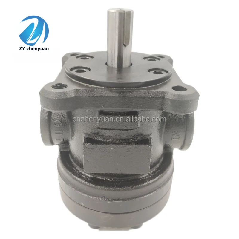
– Structural type: Horizontal installation swash plate structure, the pump body integrates a pressure compensation variable mechanism (including control slide valve, feedback piston and regulating spring); The cylinder block is connected to the input shaft through splines. The plungers are evenly distributed along the circumference of the cylinder block (10 plungers), and the swash plate inclination Angle can be adjusted by the variable mechanism (maximum inclination Angle 18°).
– Core material: The plunger is made of alloy structural steel (20CrNi2MoA, nitrided treatment, surface hardness HV900-1000, nitrided layer thickness 0.3-0.5mm); The swash plate is made of bearing steel (GCr15, quenched treatment, surface hardness HRC60-62, surface grinding accuracy Ra0.2 μm). The cylinder block is made of ductile iron (QT700-2, aged treatment, tensile strength ≥700 MPa). The pump body is made of forged carbon steel (42CrMo, quenched and tempered, hardness HB260-290).
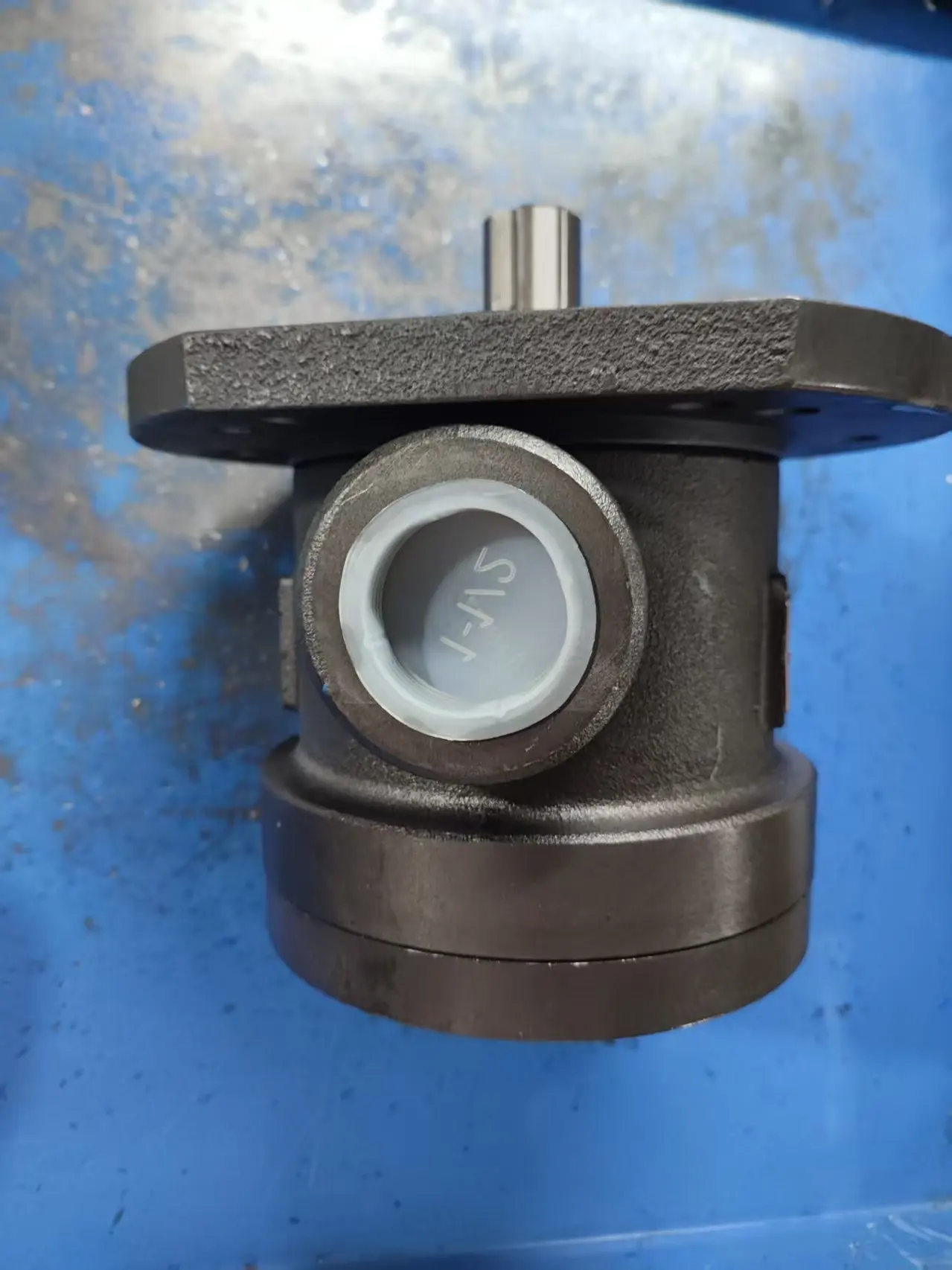
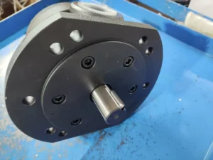
– Connection specifications: The diameter of the oil suction port (S port) is Φ 80mm, and the diameter of the oil pressure port (P port) is Φ 65mm. Both adopt metric coarse thread (S port M85×2, P port M72×2). The installation method is flange installation, compatible with ISO 7005-1 standard flange. The flange hole diameter is Φ 22mm, and the installation center distance is 160× 200mm. The input shaft is spline connected (module 3, teeth 18, pressure Angle 20°).
3. Medium and Environmental requirements
– Medium requirements: It is recommended to use L-HM 46 or L-HM 68 anti-wear hydraulic oil. For low-temperature environments (below -20℃), L-HV 68 hydraulic oil should be selected. It is compatible with phosphate ester flame-retardant hydraulic fluid. The kinematic viscosity range of the oil is 20-400 mm²/s (the optimal working viscosity is 40-100 mm²/s), the acid value is ≤0.08 mgKOH/g, and the moisture content is ≤0.1%.
– Cleanliness standard: The cleanliness of the oil should reach ISO 4406 16/13 grade (NAS 7 grade). An 80 μm coarse filter (filtration accuracy 80 μm, dirt-holding capacity ≥100 g) must be installed at the front end of the oil suction port, and a 10 μm fine filter (rated pressure ≥40 MPa, filtration efficiency β10≥200) must be forcibly installed at the oil pressure port.
– Environmental parameters: Operating environment temperature -20℃ to 80℃, relative humidity ≤95% (no condensation); It can adapt to the working conditions with vibration acceleration ≤15 m/s² (frequency 10-1000 Hz), and has a protection grade of IP55 (for the main body of the pump). It should avoid long-term exposure to environments with dust concentration > 10 mg/m³ or corrosive gases.Ii. Working Principle
This pump is a swashplate axial piston variable oil pump. Through the core mechanism of “swashplate driving the piston to reciprocate – changing the sealed volume to achieve oil suction and discharge – pressure feedback adjusting the swashplate Angle to control the flow rate”, it converts mechanical energy into hydraulic energy and realizes self-adaptive flow rate regulation. The specific working process is as follows:
1. Basic processes of oil absorption and oil pressure
The motor drives the input shaft to rotate the cylinder at high speed (800-2000 r/min). Under the action of centrifugal force and the return spring, the ball heads of the 10 plungers inside the cylinder are always in close contact with the working surface of the swash plate. Due to the initial inclination Angle (up to 18°) between the swash plate and the cylinder block axis, when the plunger rotates with the cylinder block to the lower side of the swash plate (the oil suction zone), the inclined surface of the swash plate pushes the plunger to extend outward, increasing the stroke of the plunger in the cylinder block. The sealed volume formed by the cylinder block hole and the plunger gradually expands, and the pressure inside the cavity drops to 0.03-0.05 MPa (absolute pressure), creating a vacuum. The hydraulic oil is drawn into the sealed volume through the oil suction window of the distribution plate. When the plunger rotates to the upper side of the swash plate (the oil pressure zone), the swash plate pushes the plunger to retract into the cylinder, causing a sharp reduction in the sealed volume. The oil is squeezed and pressurized to the working pressure of the system and then output to the hydraulic system through the oil pressure window of the distribution plate. Each time the cylinder block rotates once, each plunger completes one oil suction and pressure process. The 10 plungers work alternately to achieve continuous and stable oil supply.
2. Pressure compensation variable regulation mechanism
The pressure compensation variable mechanism integrated in the pump body adjusts the inclination Angle of the swash plate through the “pressure-force balance” principle, thereby controlling the plunger stroke and displacement, and achieving adaptive flow regulation.
– Low-load high-flow mode: When the system load is low (pressure < set variable pressure), the force exerted by the pressure oil at the oil pressure port on the variable control piston through the feedback channel is less than the preload of the regulating spring (the preload of the spring corresponds to the set variable pressure). At this point, the variable mechanism maintains the maximum inclination Angle of the swash plate, the plunger stroke is at its maximum (corresponding to a displacement of 150 mL/r), and the pump outputs the maximum flow rate (rated flow rate of 225 L/min), meeting the rapid action requirements of the system (such as the rapid lifting and lowering of the excavator boom).
– High-pressure low-flow mode: When the system load increases and the pressure at the oil pressure port reaches the set variable pressure (adjustable from 10 to 31.5 MPa), the thrust of the pressure oil on the control piston is balanced with the preload of the spring. When the pressure continues to rise beyond the set value, the thrust is greater than the spring force, pushing the control slide valve to move, causing the variable mechanism to drive the swash plate to deflect around the rotation center, and the inclination Angle gradually decreases. The reduction of the swash plate’s inclination Angle leads to a shortened plunger stroke, a decrease in the cylinder’s displacement per revolution, and a linear reduction in the pump’s output flow rate until the flow rate can only compensate for system leakage (minimum flow rate ≤34 L/min), achieving “high-pressure flow limiting” and reducing system energy loss.
– Overpressure unloading protection: When the system pressure rises to the peak pressure of 35 MPa, the pressure feedback signal triggers the variable mechanism to act rapidly, reducing the swash plate Angle to nearly 0°, the plunger stroke approaches zero, and the pump output flow drops sharply to the leakage level, entering the unloading state to prevent damage to the pump body and hydraulic components due to overpressure.
3. Flow distribution and stability guarantee
The distribution plate adopts an optimized dual-window symmetrical design. Transition unloading grooves and damping holes are set between the oil suction window and the oil pressure window, effectively suppressing the direct impact of high-pressure oil and low-pressure oil and reducing pressure pulsation. At the same time, the distribution plate adopts a static pressure balance structure. By applying pressure oil to the back of the distribution plate, the pressure load on its front is offset, reducing the friction and wear between the distribution plate and the cylinder block. These designs ensure that the pump’s pressure pulsation is ≤±0.2 MPa and the operating noise is ≤85 dB (under the rated condition of 1500 r/min), guaranteeing the smooth operation of the system.
Iii. Product Features and Advantages
High pressure and large flow rate, with strong power performance
The parameter combination of a rated pressure of 31.5 MPa and a rated flow rate of 225 L/min can meet the power requirements of medium and high-pressure high-flow hydraulic systems. At 2000 r/min, the maximum flow rate can reach 300 L/min, which is more than 50% higher than that of vane pumps of the same specification. With a peak pressure of 35 MPa, it can withstand heavy-load impacts and is suitable for heavy-load working conditions in construction machinery, metallurgical equipment, etc. A single pump can replace multiple small-flow pumps used in parallel, simplifying the system structure.
2. Precise variable adjustment leads to remarkable energy-saving effects
It adopts a pressure compensation variable mechanism, with a flow regulation range of 15% to 100%, pressure fluctuation ≤±0.2 MPa, and flow control accuracy ±2%. When the system is in pressure-holding or low-speed operation, the flow rate automatically drops to the leakage compensation level, which saves 25% to 35% energy compared with the fixed displacement plunger pump. The variable pressure can be set steplessly by adjusting the spring preload force, adapting to different load scenarios and avoiding the throttling loss of the relief valve in traditional systems.
3. High reliability and long service life
The plunger is nitrided with 20CrNi2MoA, with a surface hardness of HV900-1000 and excellent wear resistance. The GCr15 quenched swash plate, in combination with high-precision grinding, has a friction coefficient as low as 0.0015. The 10 plungers are evenly distributed to balance the force on the cylinder block and reduce vibration and shock. Under the condition that the oil cleanliness meets the standards, the rated working condition fault-free operation life can reach 12,000 hours, which is 40% longer than that of ordinary plunger pumps.
4. Wide working condition adaptability and strong environmental adaptability
The speed adaptation range is 800-2000 r/min, and it can be directly matched with 4-stage and 6-stage standard motors without the need for additional reduction devices. With a wide operating temperature range of -20℃ to 80℃ and an IP55 protection rating, it can adapt to various operation scenarios such as cold regions, high-temperature workshops, and mines. The anti-pollution ability is 30% higher than that of ordinary axial piston pumps, and it can still operate stably under ISO 4406 16/13 grade cleanliness.
5. Integrated design, convenient for installation and maintenance
The pump body integrates a variable mechanism, pressure feedback elements and cooling oil channels. Compared with the split design, its volume is reduced by 30%, saving installation space for the hydraulic station. It adopts a modular pump core structure. When disassembling, only the front end cover needs to be removed to take out the cylinder block – plunger assembly. The replacement time of vulnerable parts is ≤2 hours. The distribution plate and the swash plate can be ground and repaired separately, reducing the maintenance cost by 40% compared with the integral structure.
Iv. Usage Functions and Purposes
1. Core usage functions
– Variable flow regulation: Automatically adjusts the output flow according to the system pressure (33.75-225 L/min). At low loads, it outputs a large flow to achieve rapid action, and at high loads, it outputs a small flow to maintain pressure. It is suitable for compound working conditions such as “fast feed – working feed – pressure holding”, without the need for additional flow control valves.
– High-pressure power supply: It provides a stable pressure oil of 31.5 MPa for hydraulic actuators (large hydraulic cylinders, high-speed hydraulic motors), driving heavy-duty actions (such as hydraulic press pressing, excavator digging). A single pump can meet the requirements of actuators with a power of ≤100 kW.
– Pressure protection and unloading: Achieve 35 MPa overpressure unloading through a variable mechanism, replacing the safety protection function of traditional relief valves. At the same time, the system’s working pressure can be precisely controlled by adjusting the variable pressure setting value, with a pressure control accuracy of ±0.5 MPa.
– Load adaptability: The flow rate automatically changes with the load pressure. In case of sudden load changes (such as when an excavator suddenly encounters hard rock), the flow rate is quickly adjusted to match the load demand, avoiding system pressure shock and enhancing the stability of equipment operation.
2. Main application fields
– Construction machinery: Main hydraulic systems for 60-100 ton crawler excavators, working device systems for 30-50 ton wheel loaders, and drive systems for large bulldozers’ dozer blades, suitable for heavy-load compound action requirements.
– Industrial manufacturing equipment: 1000-2000 ton CNC hydraulic press pressing system, large injection molding machine (clamping force over 2000 tons) clamping/injection system, heavy-duty machine tool worktable drive system, ensuring processing accuracy under high pressure and large flow rate.
– Metallurgical and mining equipment: Roll gap adjustment systems for medium-sized rolling mills (rolling width 2000-3000mm), propulsion mechanisms for mine roadheaders (diameter 3-5 meters), and hydraulic transmission systems for ball mills in mineral processing plants, suitable for continuous heavy-load impact working conditions.
– Special equipment: Marine hydraulic steering gear systems, yaw/pitch drive systems for large-scale wind power equipment, high-pressure testing hydraulic stations for aerospace components, suitable for high-precision and high-reliability control requirements.
V. Applicable Machines and Scenarios
1. Adapt to the core machine
– Construction machinery: 60-100 ton crawler excavators, 30-50 ton wheel loaders, and bulldozers of D80 and above models.
– Industrial equipment: 1000-2000 ton CNC hydraulic presses, injection molding machines over 2000 tons, heavy-duty horizontal machining centers.
– Heavy industry equipment: 3-5 meter diameter mine tunnel boring machines, medium-sized rolling mills (rolling width 2000-3000 mm), large ball mills (volume ≥50 m³).
– Specialized equipment: Medium and high-pressure precision hydraulic station (pressure 31.5 MPa, flow 225 L/min), large hydraulic steering gear for ships, high-pressure test bench for aerospace.
2. Typical application scenarios
– Excavator excavation operation: During the compound action of the 80-ton excavator boom and bucket arm, the pump receives signals from the control system, with the variable pressure set at 28 MPa. When performing rapid action under no-load conditions, it outputs a large flow rate of 225 L/min, and the boom lifting speed is 0.8 m/s. When the load for hard rock excavation increases to 30 MPa, the flow rate automatically drops to 50-80 L/min, maintaining a stable excavation force. The pressure fluctuation is ≤±0.3 MPa, making it suitable for heavy-load mining scenarios in mines.
– Hydraulic press pressing operation: In the 1500-ton CNC hydraulic press pressing system, the pump’s rated pressure is 31.5 MPa, and the output flow rate is 225 L/min at 1500 r/min. During the rapid downward phase, the flow rate is fully open, and the downward speed is 1.2 m/s. During the pressing stage, the pressure is raised to 30 MPa, the flow rate is reduced to 30-50 L/min, and the pressing speed is 0.05-0.1 m/s, ensuring that the forming accuracy of the workpiece is ≤±0.02 mm. It is suitable for the precision forming scenarios of automotive frames and aviation aluminum alloy parts.
– Rolling mill roll gap adjustment operation: In the 2500 mm rolling mill roll gap adjustment system, the pump pressure is set at 31.5MPa. According to the feedback signal of the rolling thickness, the flow rate is adaptively adjusted within the range of 50-180 L/min. The roll gap adjustment accuracy is ± 0.01mm, ensuring that the thickness tolerance of the steel strip is controlled within ± 0.03mm, which is suitable for the continuous rolling production line scenario.
Six. Similar models
125T-61-FR-PA: The structure is exactly the same as the original model. The core differences are the rated displacement of 125 mL/r (flow rate 187.5 L/min at 1500 r/min), the maximum working pressure of 31.5 MPa, and the variable pressure adjustment range of 8-31.5 MPa. The installation dimensions and connection specifications are fully compatible, suitable for medium flow and medium high pressure scenarios (such as 50-ton excavators and 1,000-ton hydraulic presses), and the cost is 18% lower than that of the original model.
•
180T-61-FR-PA: Large-displacement model of the same series, rated displacement 180 mL/r (flow rate 270 L/min at 1500 r/min), maximum working pressure 31.5 MPa, peak pressure 35 MPa, variable pressure adjustment range 12-31.5 MPa. The structural form, material and protection level are consistent with the original model, suitable for ultra-high flow scenarios (such as 100-ton excavators, 2,000-ton injection molding machines), but the cost is 25% higher than that of the original model.
2. Cross-series alternative models
•
A4VSO150DR/31R-PPB13N00: Constant power variable axial piston pump, rated displacement 150 mL/r, rated pressure 31.5 MPa, total efficiency ≥90%. It adopts a constant power regulation mechanism, which is suitable for scenarios with large fluctuations in load power (such as crane luffing mechanisms). The energy-saving effect is 5% to 10% higher than that of pressure compensation type, and the cost is 30% higher than that of the original model.
•
PVH141R13AF30A250000002001AB010A: load sensitive type axial piston pump, the rated capacity of 150 mL/r, pressure rated 35 MPa, the response time of 40 ms or less. The flow rate is directly regulated by feedback of load pressure, which is suitable for precise control scenarios (such as CNC bending machines), and the cost is 45% higher than that of the original model.
•
CY14-1B-150: Quantitative axial piston pump, rated displacement 150 mL/r, rated pressure 31.5 MPa, volumetric efficiency ≥92%. The structure is simple and variable, with a cost 40% lower than the original model. It is suitable for scenarios with stable flow requirements (such as conveyor belt drive), but it requires additional configuration of relief valves and throttle valves to achieve pressure and flow control.
1. Oil and fluid management norms•
It is mandatory to use L-HM 46 or L-HV 68 anti-wear hydraulic oil. Different grades and types of oil are strictly prohibited from being mixed. The oil of the new pump must be replaced after the first 500 hours of operation. Subsequently, it should be replaced every 1000 hours. Before changing the oil, the oil tank and pipelines should be flushed with new oil (the flushing oil volume should be ≥ twice the system volume). After flushing, the cleanliness of the oil should reach ISO 4406 17/14 grade.
•
When the pressure difference of the oil suction filter exceeds 0.2 MPa and that of the oil pressure filter exceeds 0.5 MPa, the filter element should be replaced immediately. The moisture content (≤0.1%), acid value (≤ 0.15mgKOH /g) and viscosity (20-400 mm²/s) of the oil should be tested monthly. When the standards are exceeded, dehydration or oil change is required. It is strictly prohibited to use emulsified, deteriorated or oil containing metal impurities to avoid wear of the plunger and swash plate.
2. Installation and commissioning requirements
•
When installing, the coaxiality error between the pump shaft and the motor shaft should be no more than 0.1mm (for rigid connection) or no more than 0.3mm (for elastic connection), the flatness of the installation flange surface should be no more than 0.05mm /m, and the bolt torque should be tightened at 300 N·m to ensure good sealing and no leakage. The height from the oil suction port to the oil surface of the oil tank shall be no more than 0.6m, and the diameter of the oil suction pipeline shall be no less than Φ 80mm to reduce the oil suction resistance and prevent cavitation.
•
Before the first start-up, the pump body should be filled with hydraulic oil (added through the oil filling port), and the pump body should be manually turned 5 to 6 times to ensure that the plunger moves flexibly without jamming. When starting, it should run without load for 10 to 15 minutes (at a speed of 1000 r/min). Wait until the oil temperature rises above 30℃ before gradually loading. The pressure increase rate should be no more than 1 MPa/ minute to avoid high-pressure impact causing damage to the plunger.
•
Variable pressure adjustment needs to be carried out through a dedicated adjusting screw. Turning the screw clockwise increases the set pressure, while turning it counterclockwise decreases the pressure. When adjusting, a pressure gauge should be used for monitoring. Stabilize for 1 minute after adjusting 1/4 turn. It is recommended that the set pressure does not exceed 90% of the rated pressure (i.e., ≤28.35 MPa). After adjustment, fix it with a lock nut.
3. Operation monitoring and maintenance
•
During operation, the pump body temperature (normal ≤75℃, maximum ≤85℃), inlet and outlet pressure (P port ≤ 31.5MPa, suction port vacuum degree ≤ 0.03MPa), and operating noise (≤ 85dB) should be monitored in real time. If a sudden temperature rise of ≥10℃, abnormal pressure fluctuation or abnormal noise is detected, the machine should be stopped immediately for inspection. Focus on checking the cleanliness of the oil, the wear of the plunger or the jamming of the variable mechanism.
•
Regular maintenance should be carried out every 2,000 hours: replace seals, return springs and filter elements. Check the wear on the surface of the plunger (replace if it exceeds 0.02mm) and the flatness of the working surface of the swash plate (grind if the error is greater than 0.005mm). Disassemble and inspect the wear of the cylinder block holes every 4,000 hours (if the roundness error is greater than 0.01mm, the cylinder block needs to be replaced).
•
Maintenance should be carried out in an environment with a cleanliness level of ≥1000. Before assembling parts, they should be cleaned with aviation kerosene and coated with hydraulic oil. When assembling the plunger, avoid colliding with the working surface of the swash plate. After the variable mechanism is debugged, no-load and load tests should be conducted to ensure that the linearity error of flow regulation is ≤2%.
4. Storage and Idle protection
•
When stored for a long time, use a special metal plug to seal the oil suction port and the oil pressure port. Inject L-TSA 46 anti-rust oil into the pump body (the oil injection volume is 90% of the pump body volume). Place it in a dry and well-ventilated area (temperature 5-35℃, humidity ≤60%). Manually turn the pump by hand twice a month to prevent the plunger from adhering to the cylinder body and the metal parts from rusting.
•
Before being put into use after being idle for more than 8 months, drain the anti-rust oil and flush the pump body with L-HM 46 hydraulic oil three times. After each flush, introduce low-pressure oil (2-3 MPa) to test the flexibility of the plunger. After installation, gradually load to 50%, 75%, and 100% of the rated pressure. Run each stage for 20 minutes. After confirming that the flow rate and pressure are stable and there is no leakage, put it into formal use.


2.We has now developed into an international trading company that supplies various hydraulic machinery parts, oil pumps and valves.
3.Professional team and injectionmolding equipment.
4.In quality , quality management procedures are carried out in accordance with international standards and are implemented throughout the production process.
5.High quality service, and ensure timely delivery.
6.There is a perfect after-sale system.


