


157 157B 155 155G Hydraulic Proportional Valve 157B5110 157B5111 157B4116 155G4093 157B4128 157B4902 157B7004
Core performance parameters
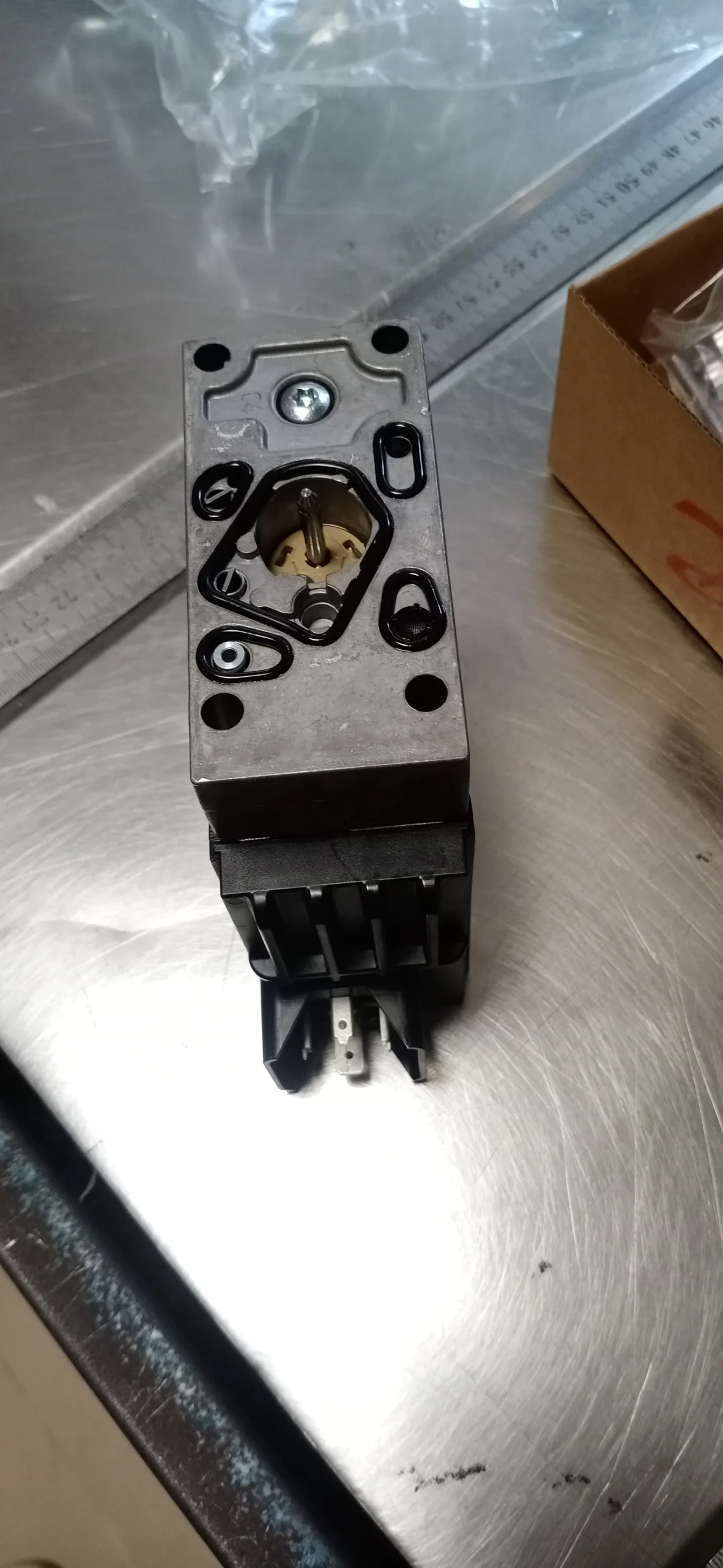
– Valve type: Direct-acting proportional directional control valve, with built-in electronic amplifier and valve core position feedback sensor, four-way spool valve structure (P oil inlet, A/B working oil port, T oil return), supports proportional coordinated control of flow and action direction, suitable for medium and large high-pressure hydraulic systems.
– Pressure and flow parameters: Rated working pressure 31.5 MPa (P port), 25 MPa (T port); Rated flow rate: 60 L/min (at a pressure difference of 1 MPa), flow regulation range: 0-60 L/min. Control accuracy: Flow repeatability accuracy ≤1%, hysteresis ≤1.5%.
– Control and response parameters: Control voltage 24V DC, command signal compatible with ± 10V voltage or 4-20mA current; The response time of the valve core is ≤80 ms, and the median alignment accuracy is ±0.02 mm. The built-in closed-loop feedback system enables precise displacement control.
– Operating characteristics: Working oil temperature -25℃ to 80℃; The maximum pressure loss during continuous operation is ≤0.8 MPa. With a protection grade of IP67, it is suitable for dusty, humid and outdoor working environments.
2. Structure and connection parameters
– Structural type: Integrated high-strength alloy cast iron valve body, stainless steel precision valve core, bidirectional proportional electromagnet, built-in amplifier and non-contact position sensor; It adopts a combination seal of high-pressure resistant polytetrafluoroethylene and fluororubber, and the valve core is treated with mirror grinding.
– Connection specification: The oil port connection is threaded (all P/A/B/T ports are G3/4″). The electrical connection is an M12×1.5 waterproof aviation plug. The installation method supports any direction, with horizontal installation preferred. The weight of the valve body is approximately 5.2kg.
3. Medium and Environmental requirements
– Medium requirements: L-HM 46/68 anti-wear hydraulic oil is suitable for normal temperature, and L-HM 32 anti-wear hydraulic oil is selected for low temperature (below -20℃). The allowable viscosity of the medium is 10-400 mm²/s, and the moisture content is ≤0.03%. It is strictly prohibited to use media containing solid particles (particle size > 10 μm) or corrosive media.
– Cleanliness standard: The oil cleanliness should reach ISO 4406 16/13 grade (NAS 9 grade). A 10 μm fine filter should be installed at the oil inlet. The filter element should be replaced immediately when the pressure difference of the filter is greater than 0.1 MPa.
– Environmental parameters: Operating environment temperature -25℃ to 80℃, relative humidity ≤98% (short-term condensation is allowed); With a protection grade of IP67, it can be directly used in outdoor construction machinery or industrial damp workshop scenarios.Ii. Working Principle
This valve is a direct-acting proportional directional control valve. Its core achieves precise control of the flow and direction of the hydraulic system through a proportional conversion mechanism of “electrical signal – electromagnetic force – valve core displacement – fluid flow regulation”, combined with closed-loop feedback. The specific process is as follows:
1. Median initial state
When neither of the proportional solenoids on both sides is energized, the centering spring group inside the valve body stabilizes the valve core in the neutral position. At this time, the P port (oil inlet) is completely closed with the A/B ports (working oil port) and the T port (return oil port), and no liquid flows through. The hydraulic actuator remains stationary, achieving reliable neutral pressure holding.
2. Direction and flow control process
– Forward action control: If the proportional electromagnet on the right is energized, the built-in electronic amplifier converts the input electrical signal into proportional electromagnetic force, overcoming the centering spring force to push the valve core to move to the left. The displacement of the valve core is directly proportional to the intensity of the input electrical signal. At this point, port P forms A passage with Port A and Port B with Port T. High-pressure oil is input into the actuator through port A to drive forward movement, and the return oil is discharged through ports B and T. The flow rate is precisely controlled by the opening degree of the throttle port formed by the displacement of the valve core.
– Reverse action control: If the proportional electromagnet on the left is energized, the valve core will move to the right under the action of electromagnetic force, connecting port P with port B and Port A with Port T, and the actuator will perform reverse action. When the input electrical signal weakens, the centering spring pushes the valve core to return to its original position, the throttle opening decreases, and the flow rate drops proportionally accordingly.
3. Closed-loop feedback for precise guarantee
The non-contact position sensor built into the valve core collects the displacement data of the valve core in real time and transmits the signal to the built-in electronic amplifier for comparison and calibration with the input command signal. If the displacement of the valve core deviates due to fluctuations in load pressure or changes in oil temperature, the amplifier will automatically adjust the electromagnetic force output, correct the position of the valve core, and ensure that the flow rate precisely matches the command signal.
Iii. Product Features and Advantages
– Precise control of large flow ratio: With a rated flow rate of 60 L/min, it is suitable for medium and large systems. The flow repeatability accuracy is ≤1%, and the hysteresis is ≤1.5%. It can achieve stepless smooth adjustment of the actuator from low speed to high speed. The closed-loop feedback design ensures that the flow rate remains stable within a ±30% fluctuation range of load pressure, making it suitable for precision heavy-duty operations.
– High integration and convenient deployment: Built-in electronic amplifier and position sensor, no need for external control module, reducing wiring volume by 60% compared to the split structure. The standardized waterproof plug and threaded connection design reduce installation and commissioning time by 50%, meeting the requirements of rapid equipment integration.
– Strong anti-pollution and environmental adaptability: The valve core mirror grinding combined with the combined sealing structure requires only ISO 4406 16/13 grade oil cleanliness, and the anti-pollution ability is 60% higher than that of servo valves. The IP67 protection grade can resist dust and water spray invasion, and the rated working condition fault-free operation life is ≥ 10,000 hours.
– Excellent high-pressure impact resistance: With a rated pressure of 31.5MPa and high-strength valve body material, it can withstand short-term high-pressure impact of 40MPa. The valve core adopts a buffer structure design. During action switching, the pressure shock is ≤5 MPa, effectively protecting the system pipeline and actuator.
Iv. Usage Functions and Purposes
1. Core usage functions
– Flow direction integrated control: A single valve integrates the dual functions of “flow regulation + direction switching”, which can replace the traditional combination solution of “directional control valve + flow control valve + relief valve”, reducing the number of system components by 40%, lowering the risk of leakage and integration costs.
– Multi-stage process precise adaptation: The flow rate is steplessly adjusted from 0 to 60 L/min through a 4-20 mA/±10 V electrical signal, perfectly meeting the multi-stage operation requirements of the actuator, namely “fast no-load – slow feed – stable pressure holding – fast return stroke”, and enhancing process stability.
– Load fluctuation adaptive: The closed-loop feedback system compensates in real time for the impact of load pressure and oil temperature changes on flow rate, avoiding sudden changes in actuator speed. It is especially suitable for scenarios with severe load fluctuations such as excavation and suppression.
2. Main application fields
In the field of medium and large-sized construction machinery: control of the boom/bucket arm of 30-80 ton crawler excavators, adjustment of the lifting mechanism of 50-100 ton wheel loaders, and control of the luffing and lifting circuit of 80-200 ton truck cranes, suitable for heavy-load operation requirements.
In the field of heavy industrial equipment: control of the main cylinder action of 1000-3000 ton hydraulic presses, regulation of the downward circuit of large metallurgical rolling mills, and control of the mold closing and injection circuit of 600-1500 ton injection molding machines, suitable for precision heavy manufacturing scenarios.
– Special operation fields: Control of the propulsion circuit of large-scale mine roadheaders, adjustment of the lifting mechanism of 50-100 ton cranes in ports, control of the compaction mechanism of garbage compression transfer stations, suitable for outdoor and harsh environment operations.
V. Applicable Machines and Scenarios
1. Adapt to the core machine
Medium and large-sized construction machinery: 30-80 ton crawler excavators, 50-100 ton wheel loaders, 80-200 ton truck cranes, large hydraulic bulldozers.
– Heavy industrial equipment: 1000-3000 ton hydraulic presses, large metallurgical rolling mills, 600-1500 ton injection molding machines, heavy forging equipment.
– Special equipment: Large-scale mine boring machines, 50-100 ton gantry cranes for ports, large-scale garbage compression equipment, auxiliary hydraulic systems for tunnel shield machines.
2. Typical application scenarios
– Heavy-load operation scenarios for excavators: As the main control valve of the 50-ton excavator boom, the valve core displacement is controlled by the electrical signal of the operating handle, achieving the action switching of the boom from “rapid lowering (60 L/min) – slow excavation (15 L/min) – smooth lifting (40 L/min)”. The flow accuracy ensures that there is no cylinder blockage during excavation and no jolt during lifting, and the operation efficiency is increased by 25%.
– Hydraulic press forming scene: It is used in the main cylinder circuit of a 2000-ton hydraulic press. The electrical signal proportional control of the main cylinder’s downward speed enables seamless switching from rapid downward movement (60 L/min) to pressing feed (8 L/min). During the holding pressure stage, the flow rate is stable at ≤2 L/min, and the dimensional accuracy error of the formed parts is ≤0.1 mm. It is suitable for precise pressing of aerospace components.
– Crane collaborative operation scenario: Equipped with a 150-ton truck crane, the luffing mechanism is controlled to operate. Load sensitivity and proportional control are coordinated to achieve precise switching between “fast adjustment and slow alignment” of luffing. During the hoisting of wind power equipment, the alignment accuracy is improved to ± 5mm, ensuring installation safety.
Six. Similar models
1. Alternative models of the same series
-157B5080: A flow model of the same structure with a rated flow rate of 40 L/min. The pressure parameters and control accuracy are consistent. It is suitable for 20-30 ton class construction machinery (such as 30-ton loaders), and the cost is 28% lower than that of the original model.
-157B5140: A high-flow model of the same series, with a rated flow rate of 80 L/min and the same pressure parameters. It is suitable for equipment ranging from 80 to 120 tons (such as the main circuit of an 80-ton excavator), but its cost is 35% higher than that of the original model.
2. Cross-series alternative models
-157B5110-N: Model without built-in amplifier, requires an external dedicated amplifier, has a more compact structure (30% volume reduction), is suitable for equipment with limited installation space (such as small shield machines), and has a cost 22% lower than the original model.
-157B5110-L: Low-pressure compatible model, with a rated working pressure of 25 MPa, consistent flow parameters, suitable for medium-pressure heavy-duty systems (such as 600-ton injection molding machines), and the cost is 18% lower than the original model.
-157C5110: The median can be of different models (Y-type median, A/B port to T port), suitable for systems that require median unloading (such as hydraulic motor drive circuits), with the same control accuracy as the original model and the same cost.
Vii. Precautions for Use
1. Medium management
– Strictly select L-HM 46/68 anti-wear hydraulic oil. L-HM 32 should be used in low-temperature environments. It is strictly prohibited to mix different grades or new and old oils. Before the new valve is used for the first time, the pipeline should be flushed with clean oil in circulation for ≥60 minutes to ensure that the cleanliness meets ISO 4406 16/13 grade.
– Check the pressure difference of the oil inlet filter weekly (replace the filter element immediately when it exceeds 0.1 MPa), test the moisture content of the oil monthly (≤0.03%), and take samples to test the cleanliness and viscosity of the oil quarterly. When emulsification, discoloration or presence of metal debris in the oil is detected, the machine must be shut down for oil change and the inner cavity of the valve body disassembled and cleaned.
2. Installation and commissioning
Before installation, confirm the oil port markings (P in, A/B in operation, T back). It is strictly forbidden to connect them in reverse to prevent the valve core from getting stuck. The output shaft is connected to the load by an elastic coupling, with a coaxiality error of no more than 0.1mm. The flange bolts are evenly tightened with a torque of 800 N·m to avoid uneven loading.
Before debugging, manually turn the wheel 3 to 5 times to confirm there is no jamming. When starting for the first time, first introduce 2-3 MPa low-pressure oil for flushing, then run at low speed (500 r/min) without load for 1.5 hours, gradually increase to the rated speed and load, and test the stability of torque output (a fluctuation of ≤±2% is normal).
For outdoor installation, ensure that the electrical plug is properly sealed and install a protective cover to enhance protection. A heat dissipation space of ≥ 150mm should be reserved on the valve body surface. When the continuous working oil temperature exceeds 80℃, a cooler should be installed to force cooling.
3. Operation and Maintenance
During operation, real-time monitoring of the valve body temperature rise (normal ≤75℃, maximum ≤85℃), inlet and outlet pressures, and action response is carried out. If the temperature rises sharply by more than 20℃, the operation becomes sluggish or the flow fluctuates by more than 5%, stop the machine immediately for inspection. Focus on checking for oil contamination, electromagnet wear or valve core jamming.
Regular maintenance should be carried out every 8,000 hours: disassemble and clean the valve core and valve sleeve, and check the fit clearance (replace the matching parts when it is greater than 0.015mm). Replace the seals and bearings, reassemble and conduct a pressure test (no leakage at 31.5 MPa pressure), and calibrate the position sensor and amplifier.
It is strictly prohibited to operate under long-term overpressure (> 31.5 MPa) or overflow (> 60 L/min). When the load suddenly changes, the pressure shock should be controlled to be ≤40 MPa to avoid rigid shock damaging the valve core. Before shutting down, it is necessary to first run at low speed without load for 10 minutes. Only when the oil temperature drops below 60℃ should the oil supply be cut off.
4. Storage protection
When stored for a long time, all oil ports should be sealed with special plugs. Anti-rust oil (with a viscosity of 46 mm²/s) should be injected into the valve body, and special lubricating grease should be applied to the valve core. Store in a dry warehouse with a temperature ranging from 0 to 45℃ and a humidity of no more than 60%. Avoid direct sunlight, heavy object compression and corrosive gas erosion. Manually turn the machine once a month to prevent component adhesion.
Before being put into use after being idle for more than 18 months, the inner cavity must be thoroughly cleaned and all seals replaced. After circulating and flushing with low-pressure oil, conduct a low-speed no-load test run for 2 hours to check the rotation direction, speed regulation and leakage (a leakage volume of ≤5 mL/min is qualified). Only after meeting the standards can it be connected to the system.


