


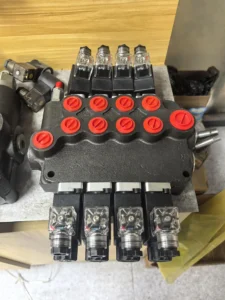
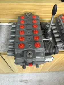

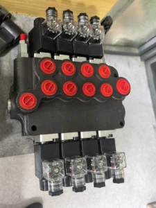
1P40 2P40 3P40 4P40 5P40 6P40 7P40 40L/Min OEM Multiway Hydraulic Monoblock Directional Manual Control Valve for Equipment
Core performance parameters
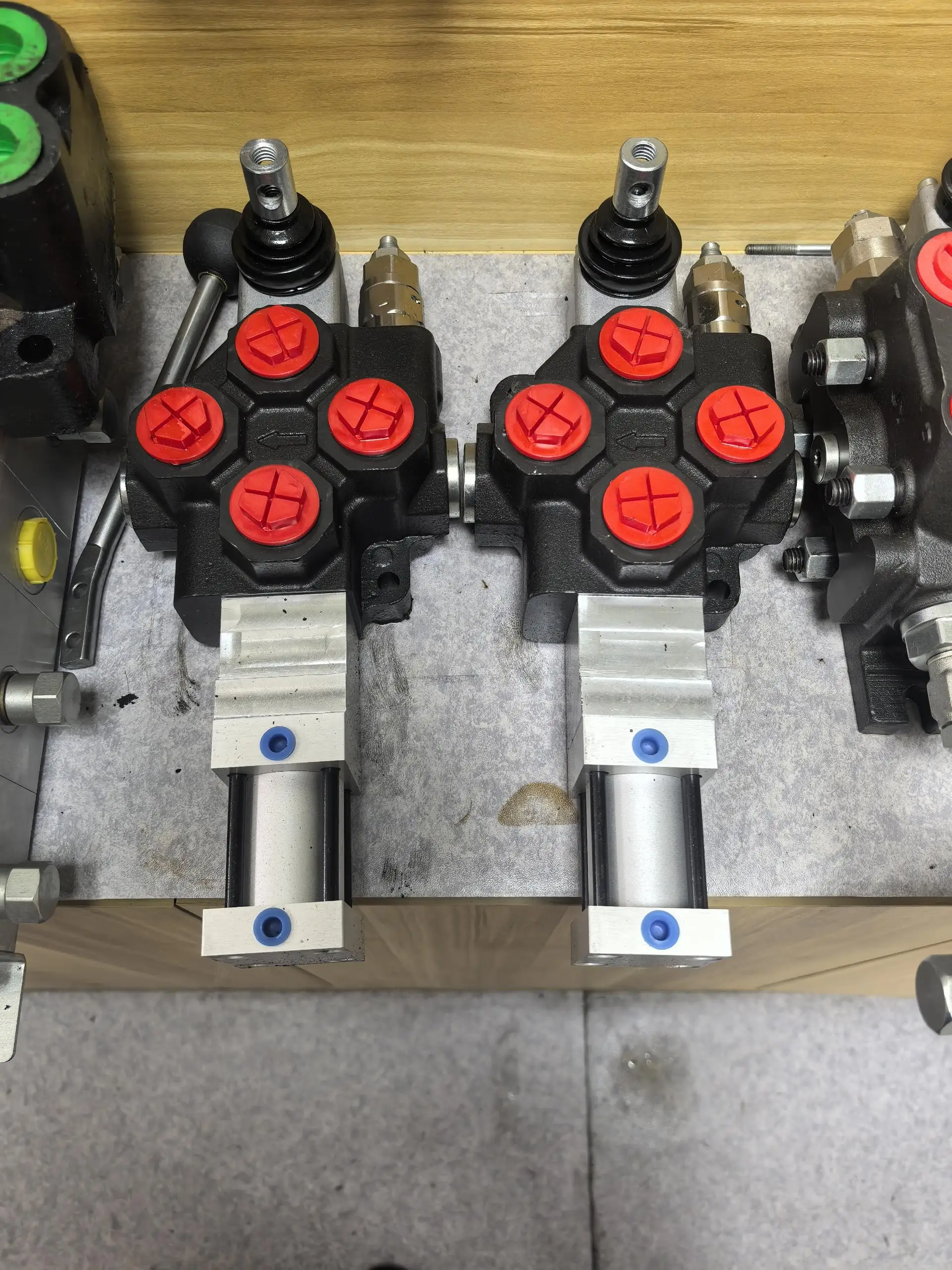
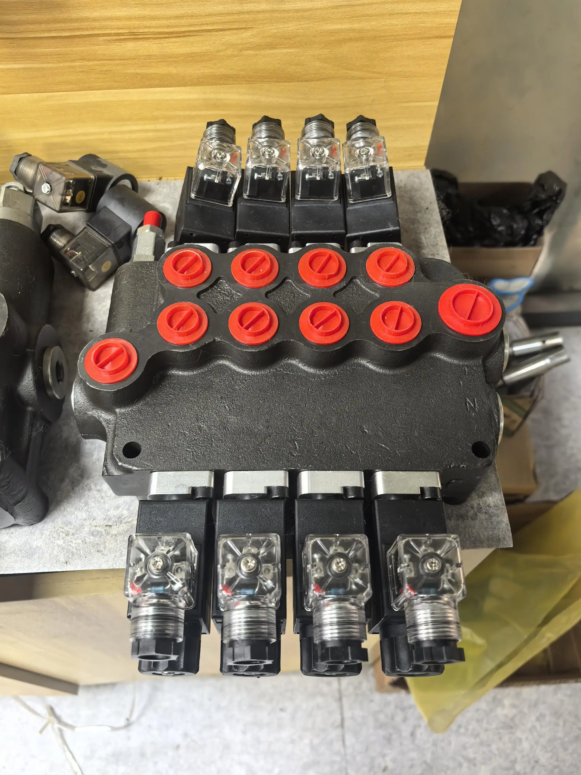
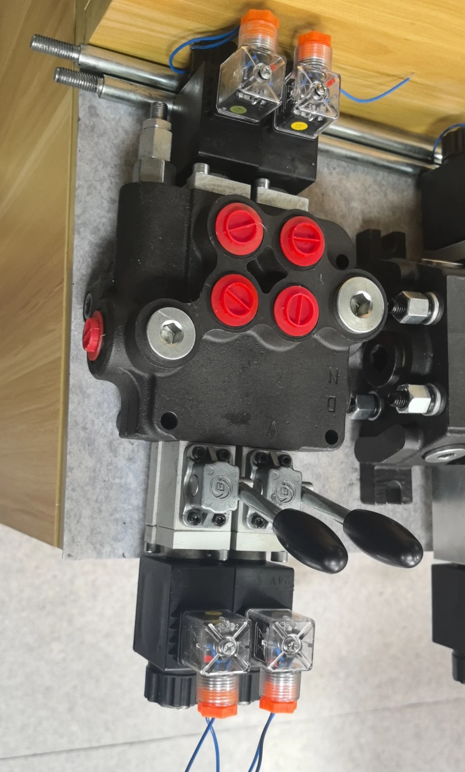
– Valve type: Two-position four-way manual directional control valve, manual lever operation (reset method is spring reset), neutral function is O-type (P/A/B/T four-port closed), suitable for medium and high-pressure high-flow hydraulic systems, achieving bidirectional action control of the actuator.
– Pressure and flow parameters: Rated working pressure 21 MPa (P port), 16 MPa (T port); The maximum allowable pressure is 25 MPa (short-term ≤10 seconds). The rated flow rate is 250 L/min (at a pressure difference of 1 MPa), suitable for the requirements of high-flow actuators.
– Operating and response parameters: Manual operating force 15-30 N (when the lever length is 200mm); Reversing stroke: 15±2 mm; The commutation response time is ≤100 ms (when operated manually quickly). It has no reliance on electric drive and is suitable for scenarios without power supply or explosion-proof.
– Operating characteristics: Working oil temperature -20℃ to 80℃; The leakage rate under rated working conditions is ≤10 mL/min. The manual operation life is no less than 100,000 times, and the rated working condition fault-free operation life is no less than 12,000 hours.
2. Structure and connection parameters
– Structural type: Spool valve structure, integrating cast iron valve body, stainless steel valve core, reset spring, manual lever and sealing assembly; It adopts a dual design of axial and radial seals, and the surface of the valve core is hardened to reduce wear. The valve body comes with an installation base and is compatible with a fixed layout.
– Core material: The valve body is alloy cast iron QT500-7 (hardness HB240-280); The valve core is made of 304 stainless steel (quenched and tempered, hardness HRC45-50). The spring is made of 65Mn spring steel (fatigue life ≥ 100,000 times). The sealing parts are made of high-pressure resistant fluororubber (temperature resistance ≤100℃).
– Connection specification: The oil port connection is flange type (all P/A/B/T ports comply with ISO 6162-1 standard); The flange sealing surface is designed as a raised surface and is compatible with wound gaskets. The installation method is bolt fixation (the center distance of the base bolts is 200× 150mm). The weight of the valve body is approximately 25 kg, and its external dimensions (length × width × height) ≈450×320×280 mm.
3. Medium and Environmental requirements
– Medium requirements: L-HM 46/68 anti-wear hydraulic oil is suitable for normal temperature. L-HM 32 is selected for low-temperature environment (below -15℃). The allowable viscosity of the medium is 10-400 mm²/s, and the moisture content is ≤0.03%. It is strictly prohibited to use media containing solid particles (particle size > 15 μm) or corrosive media.
– Cleanliness standard: The oil cleanliness should reach ISO 4406 17/14 grade. A 10 μm filter should be placed in front of the oil inlet. The filter should be replaced immediately when the pressure difference of the filter is greater than 0.1 MPa.
– Environmental parameters: Operating environment temperature -20℃ to 85℃, relative humidity ≤95% (short-term condensation is allowed); With a protection grade of IP65, it is suitable for dusty and humid scenarios such as construction machinery, mining equipment, and industrial hydraulic stations.
Ii. Working Principle
This valve is a two-position four-way manual control directional control valve. The core realizes the direction control of the actuator through the mechanism of “manual operation of valve core displacement – oil port on-off switching – spring return to center”. The specific process is as follows:
1. Median initial state
When the manual lever is not operated, the reset spring stabilizes the valve core in the neutral position (O-type function). At this time, port P (oil inlet), Port A (working oil port 1), Port B (working oil port 2), and Port T (oil return) are all in a closed state. The actuator has no oil inflow or outflow, remains stationary, and achieves neutral pressure holding.
2. Reversing working process
When the manual lever is pulled to one side, the driving force of the lever overcomes the spring force to push the valve core to move axially to the working position 1: Port P is connected to port A, and Port B is connected to Port T. High-pressure oil enters the first chamber of the actuator through port P and port A, driving its forward movement. The return oil from the other chamber of the actuator is discharged through Port B and Port T. After releasing the lever, the reset spring pulls the valve core back to the neutral position, the oil port closes, and the actuator stops moving.
3. Reverse action control
When the manual lever is pulled to the other side, the valve core moves to the working position 2, and the oil port passage switches to P port connecting with B port, and A port connecting with T port. High-pressure oil enters the other chamber of the actuator through port P and port B, driving it to move in the opposite direction. The return oil is discharged through Port A and Port T. After releasing the lever, the valve core returns to the middle position under the action of the spring, completing one bidirectional action cycle.
Iii. Product Features and Advantages
– Strong adaptability to large flow rates: With a 40mm large bore design and an optimized flow channel, the rated flow rate reaches 250L /min, which is 60% higher than that of the same type of small-bore valves. It is suitable for large flow actuators such as loaders and hydraulic presses, eliminating the need for multiple valves in parallel and simplifying the system structure.
Manual operation is reliable and durable: No reliance on electric drive, suitable for special outdoor scenarios without power supply, explosion-proof, etc. The operating force of the manual lever is only 15-30 N, making it easy to operate. The valve core hardening treatment combined with double sealing ensures a manual reversing life of no less than 100,000 times, which is 50% longer than that of ordinary manual valves.
– Excellent median pressure holding performance: The O-type median can seal all four ports. After the actuator stops, the leakage is ≤10 mL/min, and the pressure holding time is ≥1.5 hours (under a load of 10 MPa). Static pressure holding can be achieved without additional pressure holding valves, making it suitable for scenarios such as hydraulic lifts and clamping mechanisms.
– Anti-pollution and convenient maintenance: The valve core fit clearance is reasonable. The oil cleanliness requirement is only ISO 4406 17/14 grade, and the anti-pollution ability is 40% higher than that of the electromagnetic directional control valve. The structure is simple, and the vulnerable parts (seals, springs) have strong versatility. Replacement does not require special tools, and the maintenance cost is low.
Iv. Usage Functions and Purposes
1. Core usage functions
– Bidirectional control of actuators: A single valve enables forward, reverse and stop control of actuators such as hydraulic cylinders and hydraulic motors, replacing the “check valve + throttle valve” combination scheme. This reduces the number of system components by 30% and lowers the risk of leakage.
– Median pressure holding and emergency operation: The O-type median function can achieve static pressure holding of the actuator, making it suitable for scenarios that require long-term stopover. Manual operation can be used as an emergency control measure, allowing the equipment to be controlled even when the electric drive system malfunctions, thereby enhancing operational safety.
– Flow regulation compatibility: A throttle port can be integrated inside the valve body (optional). By adjusting the opening degree of the throttle port, the speed of the actuator can be fine-tuned, making it suitable for scenarios with basic requirements for speed accuracy (such as hydraulic material pushing mechanisms), without the need to install an additional speed control valve.
2. Main application fields
In the field of construction machinery: lifting and steering circuits for 30-60 ton loaders, bucket action control for 10-20 ton excavators, vibration mechanism switching for 20-40 ton rollers, suitable for outdoor heavy-load operations.
In the field of industrial hydraulic equipment: main cylinder action control of 500-1500 ton hydraulic presses, lifting and reversing of large hydraulic lifts, drive circuit switching of heavy-duty conveying equipment, suitable for high-flow industrial scenarios.
– Special operation fields: Bucket action control of mine loaders, luffing circuits of small cranes in ports, control of hydraulic equipment in explosion-proof workshops, suitable for conditions without power supply, high dust or explosion-proof.
V. Applicable Machines and Scenarios
1. Adapt to the core machine
Construction machinery: 30-60 ton loaders, 10-20 ton excavators, 20-40 ton rollers, 10-15 ton mine loaders.
– Industrial hydraulic equipment: 500-1500 ton hydraulic presses, 5-10 ton hydraulic lifts, heavy-duty plate conveyors.
– Special equipment: Small cranes for ports, explosion-proof hydraulic clamping equipment, auxiliary hydraulic equipment for mines.
2. Typical application scenarios
– Loader lifting scenario: As the main valve of the 40-ton loader lifting circuit, when the lever is turned to the working position 1, port P and port A are connected, driving the lifting cylinder to rise (pressure 18 MPa, flow 200 L/min). Release the lever to hold the pressure in the middle position to prevent the bucket from descending. Reverse pull the lever to achieve the descent, which is suitable for the earthwork transfer operation at the construction site.
– Hydraulic press scenario: It is used in the main cylinder circuit of a 1000-ton hydraulic press. Manually switch to working position 1 to drive the main cylinder downward for pressing (pressure 21 MPa, flow 220 L/min), switch to working position 2 to achieve return stroke, and the neutral pressure holding ensures stable pressure during the pressing process. It is suitable for metal forging processing.
– Mine scraper scenario: Equipped with a 15-ton mine scraper bucket circuit, manually operate and control the bucket’s “loading – lifting – unloading” actions. IP65 protection is suitable for the underground dusty environment. The design without electric drive avoids the impact of underground power supply failures on operations. It can work continuously for 12 hours a day without failure.
Six. Similar models
1. Alternative models of the same series
-2P32: A small-bore model of the same structure, with a bore of 32mm, a rated flow rate of 160L /min, and consistent pressure parameters. It is suitable for medium and small flow systems (such as 20-ton loaders), and its cost is 25% lower than that of the original model.
-2P50: A large-diameter model of the same series, with a diameter of 50mm, a rated flow rate of 400L /min, and the same pressure parameters. It is suitable for ultra-large flow systems (such as 1500-ton presses), but its cost is 40% higher than that of the original model.
2. Cross-series alternative models
-2P40-O: Different median performance models (O type changed to H type, P port connected to T port, A/B port closed), suitable for systems requiring median unloading (such as hydraulic motor drive circuits), with the same pressure and flow rate, and the same cost.
-2P40-M: Medium-pressure compatible model, rated working pressure 16 MPa, with the same diameter and flow rate, suitable for medium-pressure systems (such as 500-ton presses), and the cost is 20% lower than the original model.
-3P40: Three-position four-way model, adding an intermediate working position to achieve flow classification, suitable for scenarios requiring multi-speed control (such as fast and slow speed switching of hydraulic lifts), with a cost 35% higher than the original model.
Vii. Precautions for Use
1. Medium and Selection management
– Strictly select L-HM 32/46/68 anti-wear hydraulic oil. It is strictly prohibited to mix oils of different grades. Select the type based on the system pressure (≤21 MPa) and flow rate (≤250 L/min). It is strictly prohibited to use beyond the parameters to avoid valve core jamming.
Before the new system is used for the first time, the pipeline should be flushed with clean oil for more than 60 minutes to remove installation impurities before installing the valve. When changing the hydraulic oil in the system, the inner cavity of the valve body must be cleaned simultaneously and the sealing parts replaced.
2. Installation and commissioning
Before installation, confirm the oil port markings (P inlet, A/B working, T return). It is strictly forbidden to connect them in reverse to cause pressure shock. When making flange connections, the gasket should be aligned with the oil port, and the bolts should be evenly tightened with a torque of 800 N·m to prevent high-pressure leakage.
Before debugging, manually turn the lever 3 to 5 times to ensure that the valve core is not stuck. Introduce low-pressure oil (5 MPa) to test the on-off status of the oil ports at each working position to ensure there is no internal leakage. Test the median pressure-holding performance (a pressure drop of ≤0.5 MPa within 30 minutes at 10 MPa pressure is considered normal).
When installed outdoors or underground, a dust cover should be added to the manual lever to prevent dust from entering and affecting operation. The valve body should be installed horizontally and fixed to avoid tilting which may cause uneven force on the valve core.
3. Operation and Maintenance
During operation, check the flexibility of manual lever operation once a week. If there is an increase in operating force or jamming, disassemble and clean the valve core and apply special lubricating grease. Check the leakage of each oil port every month. When the leakage exceeds 15 mL/min, the sealing parts need to be replaced.
Regular maintenance every 6,000 hours: Disassemble the valve body and check the wear of the valve core (replace when the wear is greater than 0.03mm). Replace the seals and springs, reassemble and test the reversing performance and pressure-holding effect to ensure compliance.
It is strictly prohibited to forcibly operate the lever when the system is under pressure (as it may cause deformation of the valve core). Avoid frequent and rapid reversing (more than once per second) to prevent excessive wear of the seals. Before long-term shutdown, the valve core should be placed in the neutral position and the oil supply should be turned off.
4. Storage protection
When stored for a long time, all oil ports should be sealed with special plugs, anti-rust oil should be injected into the valve body, and lithium-based grease should be applied to the valve core. Store in a dry warehouse with a temperature ranging from 0 to 45℃ and a humidity of no more than 60%. Avoid direct sunlight, heavy object compression and corrosive gas erosion. Manually operate the lever once every three months.
Before being put into use after being idle for more than 18 months, thoroughly clean the inner cavity and replace all the seals. After circulating and flushing with low-pressure oil, test the performance of each working position. Only after meeting the standards can it be connected to the system.


