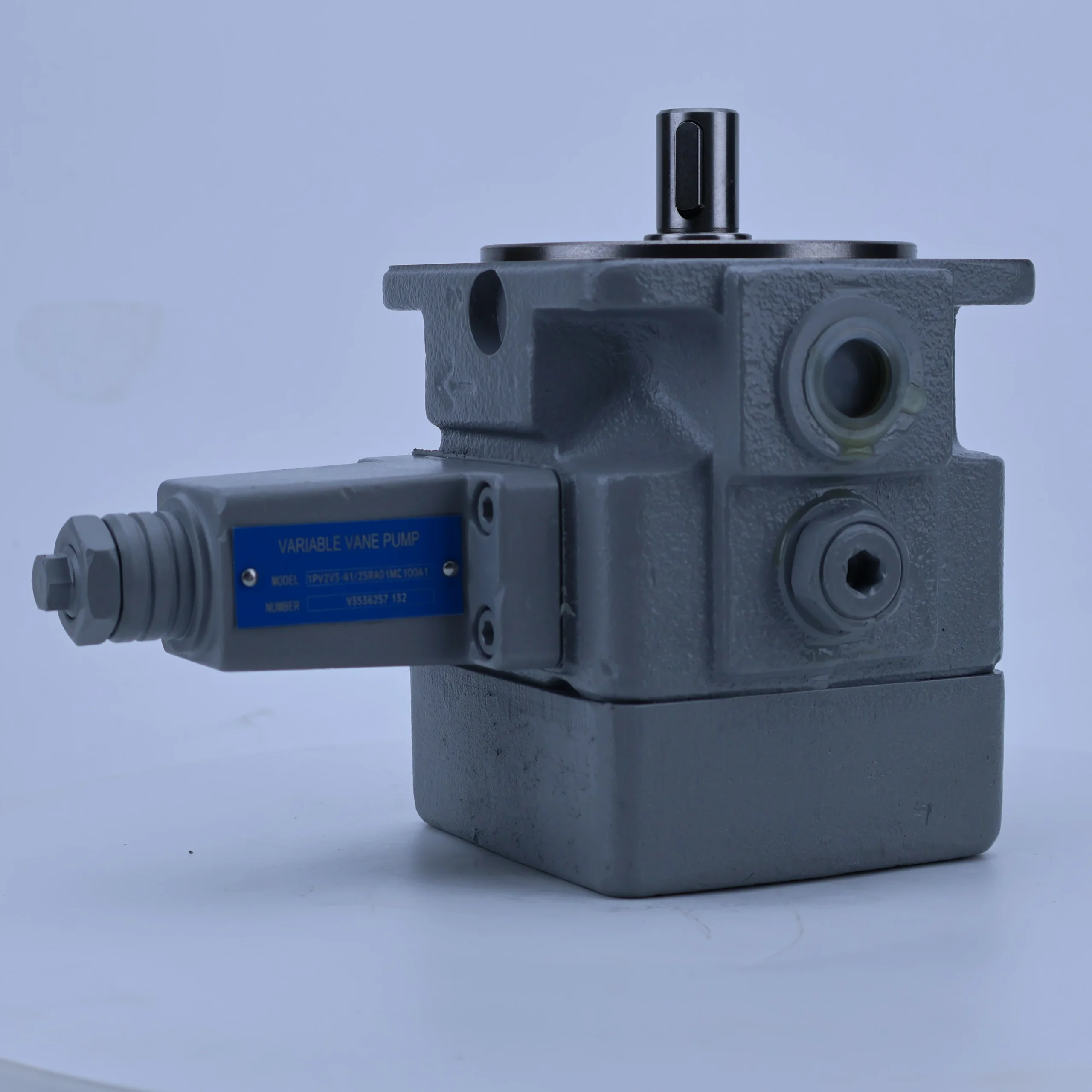

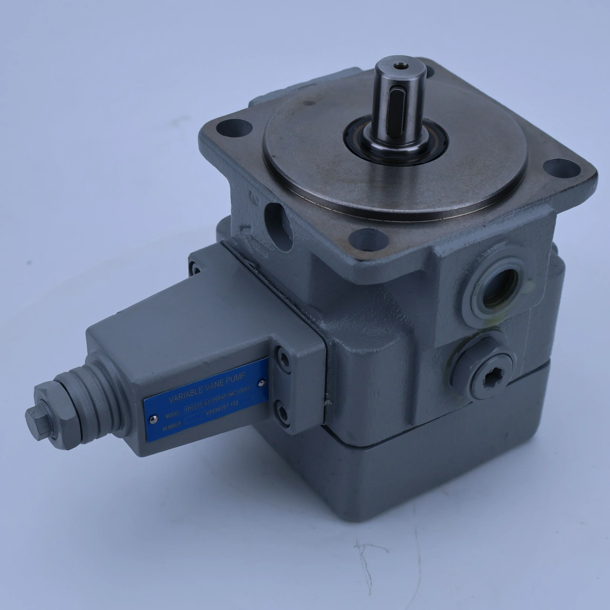
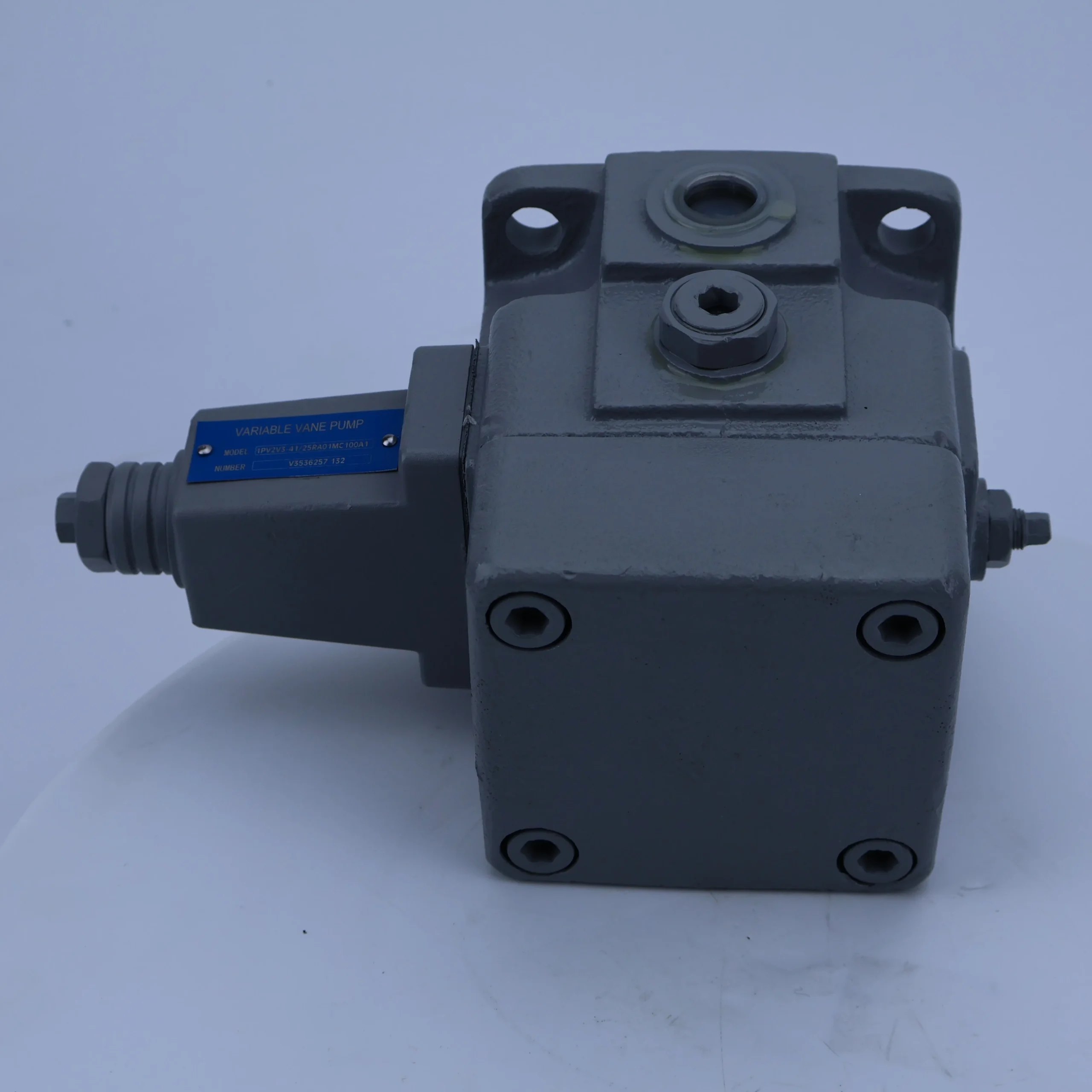
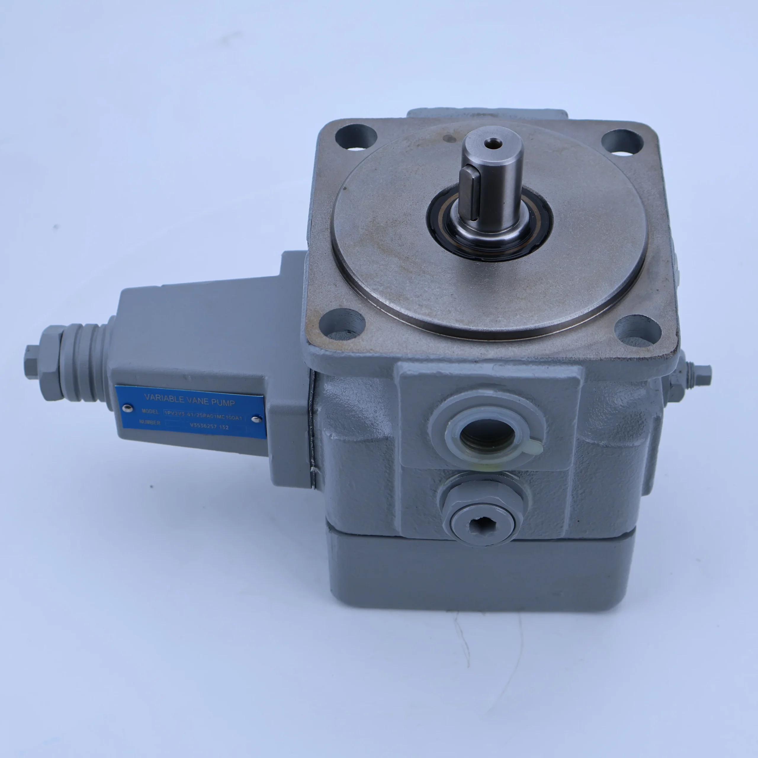
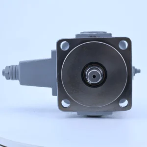
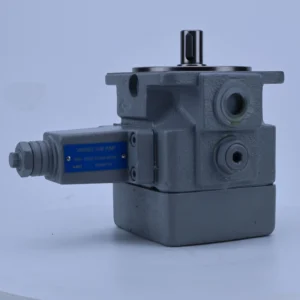
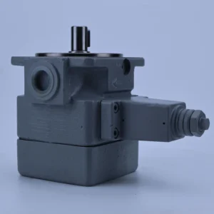
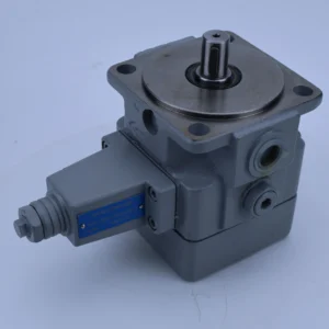
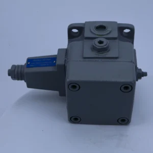

1PV2V3 1PV2V3-3X/40 1PV2V3-3X/63 1PV2V3-4X/12 1PV2V3-4X/25 Hydraulic Variable Displacement Vane Pump 1PV2V3-40/25RA01MC25A1
1. Basic performance parameters- Pump body type: Single-acting variable vane pump, integrated pressure compensation variable mechanism and relief valve, supports unidirectional rotation, suitable for medium and low pressure hydraulic systems
– Displacement and pressure parameters: Variable displacement range 25-40 cc/rev (model “40/25” corresponds to maximum/minimum displacement); The rated working pressure is 160 bar, the maximum allowable pressure is 210 bar (short-term ≤10 seconds), and the return oil back pressure is ≤3 bar
– Speed and flow parameters: Rated speed 3000 rpm, maximum speed 3600 rpm (short time ≤5 minutes), minimum stable speed 600 rpm; The maximum output flow rate at the rated speed is 120 L/min (40 cc/rev×3000 rpm÷1000), and the minimum flow rate is 75 L/min (25 cc/rev×3000 rpm÷1000).
– Efficiency parameters: Rated working condition volumetric efficiency ≥92%, total efficiency ≥86%; The pressure compensation response time is ≤50 ms, and the flow regulation accuracy is ±2%
2. Structure and connection parameters
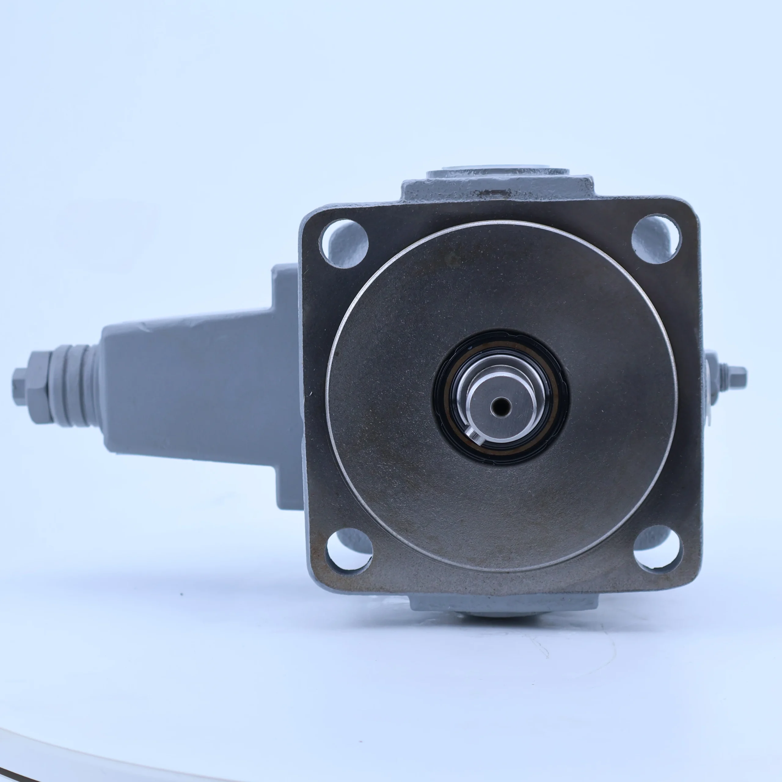
– Structural type: Cast iron pump body, surface phosphating anti-rust treatment; Alloy steel rotor (hardness HRC58-62), copper-based alloy blades, wear-resistant cast iron stator, double-end mechanical seal + lip seal combination
– Installation and connection specifications: Flange installation (compatible with ISO 3019-1 standard, “RA01” corresponds to installation positioning); Oil port threads: Suction port G1 1/4, outlet port G1, control port G1/8; The output shaft is connected by involute splines (7-tooth / 9-tooth options are available). The overall weight is approximately 15 kg, and the external dimensions (length × width × height) ≈300×220×180 mm
– Protection grade: IP65, suitable for dusty and humid industrial and construction machinery environments
3. Medium and Environmental requirements
– Medium requirements: Compatible with L-HM 32/46/68 anti-wear hydraulic oil, allowable medium viscosity range 17-37 mm²/s, moisture content ≤0.02%, solid particle size ≤10 μm
– Environmental parameters: Operating environment temperature -20℃ to 80℃, relative humidity ≤95%; The cleanliness of the oil should reach ISO 4406 14/11 grade
– Filtration requirements: A filter screen of ≥100 mesh should be installed on the oil suction side, and the filtration accuracy on the oil return side should be ≤25 μm. It is recommended to install a high-pressure filter (accuracy ≤10 μm).
Ii. Working Principle
This pump is a single-acting variable vane pump. Its core realizes the conversion of mechanical energy and hydraulic energy and the self-adaptive regulation of flow through the mechanism of “rotor vane volume change + pressure feedback variable regulation”. The specific process is as follows:
1. Core mechanism of power transformation
The motor drives the rotor to rotate. Under the dual action of centrifugal force and root pressure oil, the tips of the blades closely adhere to the inner surface of the stator. The rotor and stator are eccentrically arranged, and the adjacent blades, rotor, stator and distribution plate form a sealed working chamber. When the rotor rotates clockwise, the volume of the right working chamber gradually increases as the rotor rotates, creating a vacuum and drawing in oil through the oil suction port. The volume of the left working chamber gradually decreases, and the oil is squeezed to generate pressure. It is guided to the oil outlet through the distribution plate and discharged, driving the actuator to act.
2. Variable regulation and protection mechanism
Integrated pressure compensation variable mechanism and relief valve: When the system pressure rises to the set value, the pressure oil pushes the variable piston to change the eccentricity of the stator and rotor, causing the displacement to decrease from 40 cc/rev to 25 cc/rev, achieving an adaptive regulation of “pressure increase → flow decrease” and reducing energy loss. When the pressure exceeds the maximum allowable value of 210 bar, the relief valve is fully open to unload, guiding the oil back to the suction chamber to prevent the pump body from being overloaded and damaged. The distribution plate adopts a pressure self-compensation design to reduce axial leakage and maintain high volumetric efficiency.
Iii. Product Features and Advantages
– Variable energy saving and high efficiency: The pressure compensation variable mechanism can automatically adjust the displacement according to the load demand, saving 20%-30% energy compared with the fixed displacement pump. With a wide displacement range of 40/25cc /rev, it is suitable for scenarios with large fluctuations in load flow, and the flow regulation response time is ≤ 50ms
– Smooth operation and low noise: The copper-based alloy blades precisely fit the stator surface, and with the modified blade chamfer design, the operating noise is ≤72 dB (at 1 meter), which is 5-8 dB lower than that of conventional vane pumps. The flow pulsation rate is ≤3%, making it suitable for high-precision control scenarios
– High wear resistance and long service life: The alloy steel rotor is nitrided, the copper-based blades contain self-lubricating components, the inner surface of the stator is precisely honed, and the blade wear is ≤ 0.05mm per 10,000 hours. The static leakage of the double-seal design is ≤1.5 mL/min, and the trouble-free operation life under rated conditions is ≥ 15,000 hours
– Strong installation adaptability: Compatible with both flange and foot mounting methods, the oil port supports 180° rotation adjustment. The wide temperature range of -20℃ to 80℃ is suitable for high and low temperature environments, and the rated pressure of 160 bar covers most medium and low pressure industrial scenarios
Iv. Usage Functions and Purposes
1. Core usage functions
– Variable flow adaptive fuel supply: Automatically adjust the output flow (25-40 cc/rev) according to the system load pressure to provide matching power for fluctuating loads and avoid energy waste caused by flow redundancy
– Dual system pressure protection: The variable mechanism enables dynamic pressure regulation, and the relief valve provides overload protection. These dual safeguards prevent damage to hydraulic components, replace external variable valve groups, and enhance system integration
– High-precision power transmission: Low flow pulsation (≤3%) and fast response (≤ 50ms) features ensure the smooth operation of the actuator, making it suitable for scenarios with position control accuracy ≤ 0.1mm
2. Main uses
As the core power component of the medium and low pressure fluctuating load hydraulic system, it connects the motor and the actuator, providing energy-saving power for the precise movements and load fluctuation scenarios of various industrial machinery. It is the preferred power source for automated production lines, precision machine tools and other equipment.
V. Applicable Machines and Scenarios
1. Adapt to the core machine
– Industrial machinery: 300-500 ton injection molding machines, feed systems for CNC lathes/milling machines, high-precision grinders, fully automatic packaging machines, hydraulic presses
– Construction machinery: Auxiliary action systems for small excavators, lifting mechanisms for forklifts, luffing mechanisms for hydraulic cranes
– Special equipment: Automated assembly production lines, precision press-fitting equipment for electronic components, hydraulic test benches, hydraulic drive systems for medical imaging equipment
2. Typical application scenarios
– Injection molding machine forming scenario: It is equipped with a 400-ton injection molding machine. During the mold locking stage, it automatically adjusts to a large displacement of 40 cc/rev to achieve rapid mold locking (time ≤2 seconds). During the pressure holding stage, it reduces to a small displacement of 25 cc/rev for energy-saving pressure holding. The pressure stability error is ≤1%, and the energy consumption per shift is 25% lower than that of a fixed displacement pump
– CNC milling machine feed scenario: Drive the XYZ axis feed mechanism of the milling machine, with flow pulsation ≤3% to ensure feed accuracy of ± 0.02mm; When the load changes, the displacement responds within 0.1 seconds, quickly switching between fast feed (40 cc/rev) and industrial feed (25 cc/rev) modes, increasing processing efficiency by 15%
– Precision press-fitting scenarios: Compatible with electronic component press-fitting equipment, with a displacement adjustment of 25-40cc /rev to meet different press-fitting force requirements (5-20kN), fast pressure feedback response, press-fitting depth accuracy ≤ 0.05mm, meeting the assembly requirements of precision components such as chips and connectors
Six. Similar models
1. Different models of the same series displacement
-1PV2V3-32/20RA01MC25A1: Maximum/minimum displacement 32/20 cc/rev, rated flow 96/60 L/min, rated pressure 160 bar, suitable for small precision systems (such as small grinding machines, 3C product assembly equipment), 20% smaller in size, weight approximately 12 kg
-1PV2V3-50/32RA01MC25A1: Maximum/minimum displacement 50/32 cc/rev, rated flow 150/96 L/min, maximum pressure 210 bar, suitable for large fluctuating load systems (such as 500-ton injection molding machines, large presses), with a 25% power increase
2. Models with the same displacement but different functions
-1PV2V3-40/25RA01MC25A1-M: Manual variable adjustment mechanism model, suitable for simple scenarios with fixed pressure, featuring a simple structure and 18% lower cost
-1PV2V3-40/25RA01MC25A1-E: Electro-hydraulic proportional control model, supporting PLC remote adjustment of displacement and pressure, control accuracy ±0.5%, suitable for automated production lines, with a 45% higher cost
-1PV2V3-40/25LA01MC25A1: Left-rotating installation model, suitable for equipment with limited motor rotation direction. The oil outlet direction is reversed, while other performances remain the same
Vii. Precautions for Use
Installation and commissioning
When installing, ensure that the coaxiality error between the pump shaft and the motor shaft is ≤ 0.1mm. Use an elastic coupling for connection. Radial force (≥ 80N) must not be directly applied to the pump shaft to avoid eccentric offset of the stator and rotor
The oil suction pipeline should be short and straight (length ≤1.5 meters, diameter ≥ 32mm), and the distance between the oil suction port and the bottom of the oil tank should be ≥ 150mm to avoid excessive oil suction resistance causing cavitation. The pipeline connection adopts oil-resistant sealing gaskets to ensure no air leakage. It is recommended to install a vacuum gauge (vacuum degree ≤0.02 MPa) on the oil-suction side.
Before the first start-up, fill the pump cavity with hydraulic oil and manually turn the wheel 5 to 6 times to confirm that the blades can extend and contract flexibly. When starting up, first open the oil suction valve and run it no-load at low pressure (50 bar) and low speed (1000 rpm) for 30 minutes. Gradually increase it to the rated parameters and calibrate the pressure-displacement curve of the variable mechanism at the same time
– Reverse rotation operation is prohibited (the blade chamfer and the distribution plate design are adapted to the fixed rotation direction). For outdoor installation, a protective cover should be added. A heat dissipation space of ≥ 200mm should be reserved around the pump body. When the ambient temperature exceeds 40℃, forced heat dissipation is required
2. Operation and Maintenance
During operation, the pump body temperature (normal ≤80℃, maximum ≤90℃), outlet pressure and noise should be monitored daily. If the temperature rises sharply by more than 10℃, the pressure fluctuates by more than 5 bar or the noise exceeds 80 dB, stop the machine immediately for inspection. Focus on checking the contamination level of the oil (once every two months), blade wear or jamming of the variable mechanism
– Regular maintenance cycle: Replace the hydraulic oil and the three-stage filter every 5,000 hours; Disassemble and inspect every 12,000 hours. Replace when the blade thickness wear is ≥ 0.1mm or the inner surface of the stator is scratched. At the same time, replace the sealing parts and the variable mechanism spring. Calibrate the pressure setting value of the variable mechanism every 3,000 hours
No-oil idling is strictly prohibited (idling for more than 3 seconds can easily cause scratches on the blades and stator). Long-term full-load operation (single time ≤2 hours) is prohibited at the minimum displacement (25 cc/rev). Before the system is shut down, it needs to be reduced to low pressure and run no-load for 5 minutes. After the oil temperature is ≤60℃, the oil source should be cut off
3. Storage and Protection
When stored for a long time, use a special plug to seal the oil port, inject anti-rust oil (about 100 mL) into the pump cavity, and apply lithium-based grease to the splines of the output shaft. Store in a dry warehouse with a temperature ranging from 0 to 45℃ and a humidity of no more than 60%. Avoid direct sunlight and heavy object compression. Manually turn the machine once every two months
Before putting the pump into use after being idle for more than 12 months, thoroughly clean the pump cavity and pipelines, replace the seals and hydraulic oil, and regrind the mating surface between the distribution plate and the stator. Conduct a low-speed no-load test run for 20 minutes to detect the variable response and leakage (≤1.5 mL/min is normal). Only after meeting the standards can it be connected to the system


