
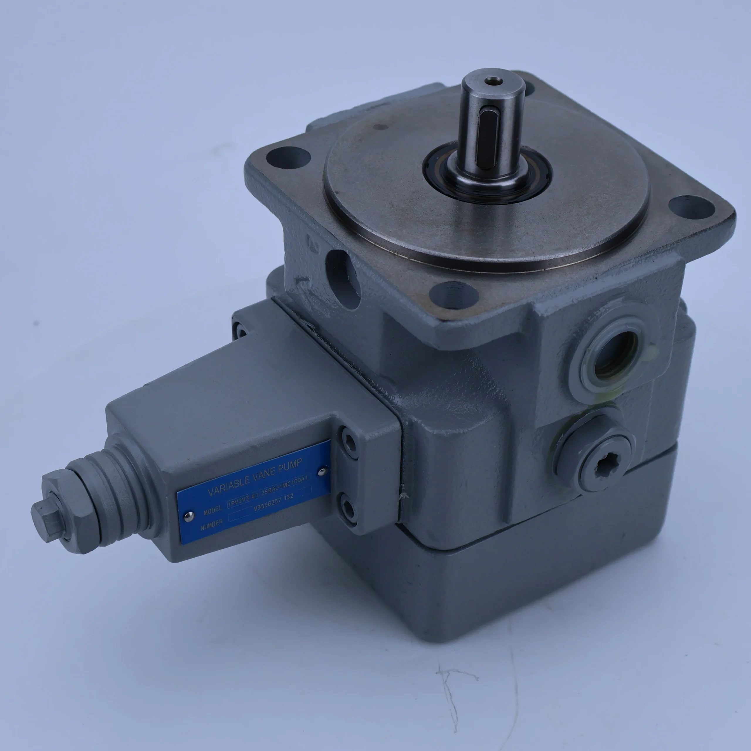
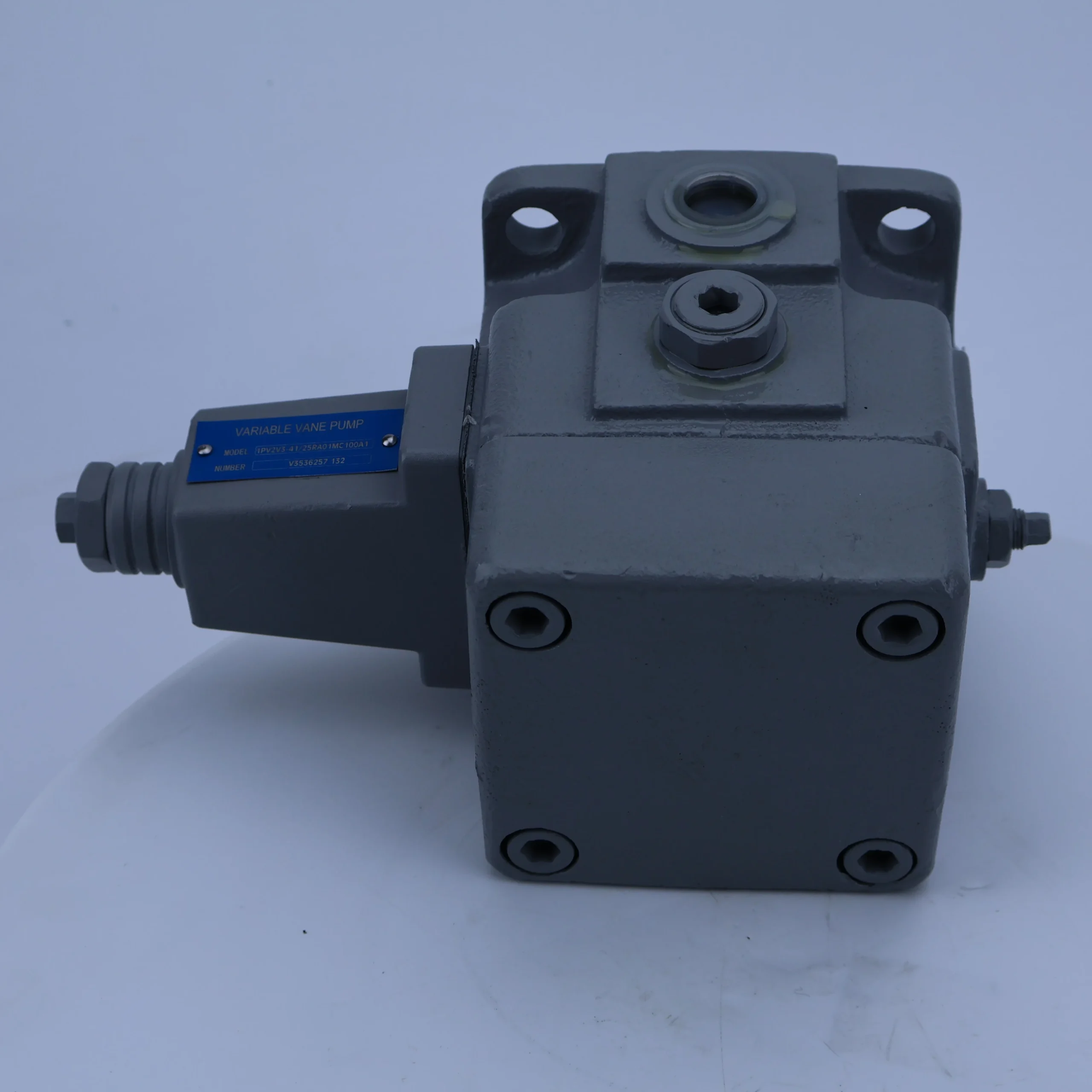
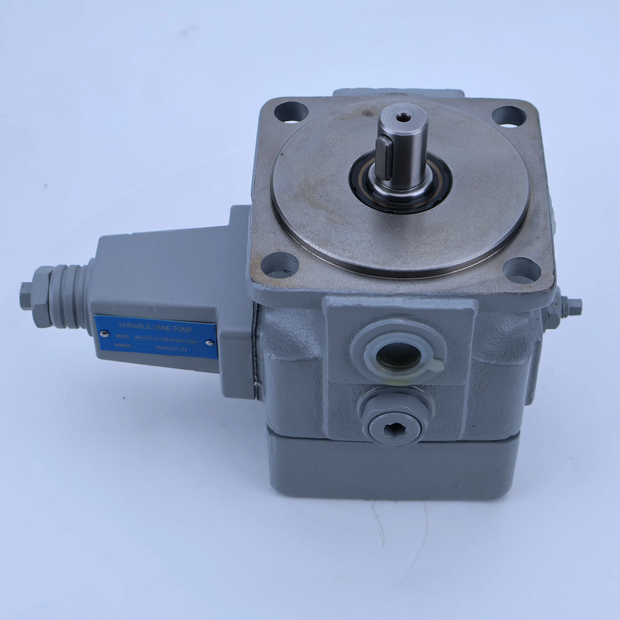


1PV2V3-41/25RA0MC100A1 Oil Pump 1PV2V3 1PV2V4 1PV2V5 1PV2V3-41 Hydraulic Variable Displacement Vane Pump
Core performance parameters•Valve type: Pressure-compensated variable vane pump, single-stage single-acting structure, adopts eccentric rotor-stator design, featuring self-adaptive flow regulation, pressure limiting and low-pressure high-flow output characteristics, suitable for the power supply requirements of medium and high-pressure hydraulic systems.
•Pressure rating: Rated working pressure 21 MPa (210 bar), maximum working pressure 25 MPa (250 bar, duration ≤10 minutes); The variable pressure setting range is 8-21 MPa (which can be adjusted steplessly by the adjusting screw), and the pressure fluctuation is ≤±0.3 MPa (at rated flow).
•Flow parameters: Rated displacement 25 mL/r (corresponding to model “25” marking), rated flow 37.5 L/min at rated speed 1500 r/min; The rotational speed range is 500-1800 r/min, and the flow rate is linearly matched with the rotational speed (12.5 L/min at 500 r/min and 45 L/min at 1800 r/min). The variable adjustment range is 10%-100% (3.75-37.5 L/min).
•Efficiency and power: Volumetric efficiency ≥88% (under rated conditions), total efficiency ≥82% (under rated conditions); The shaft power at the rated speed is ≤15 kW, and the power of the matching motor is recommended to be 11-15 kW (matched according to the actual working conditions). The idle power loss is ≤1.2 kW (at 1500 r/min without load).
2. Structure and connection parameters
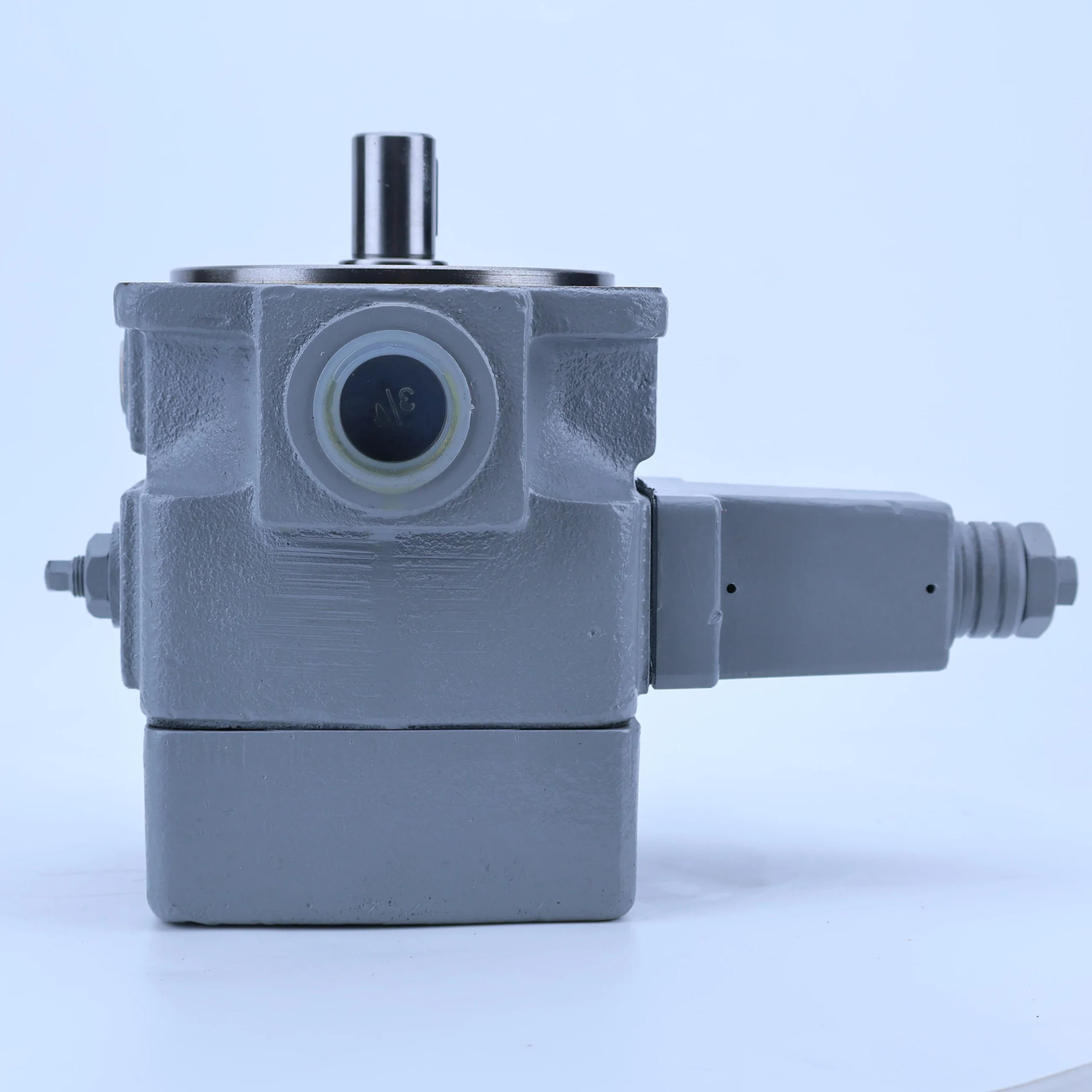
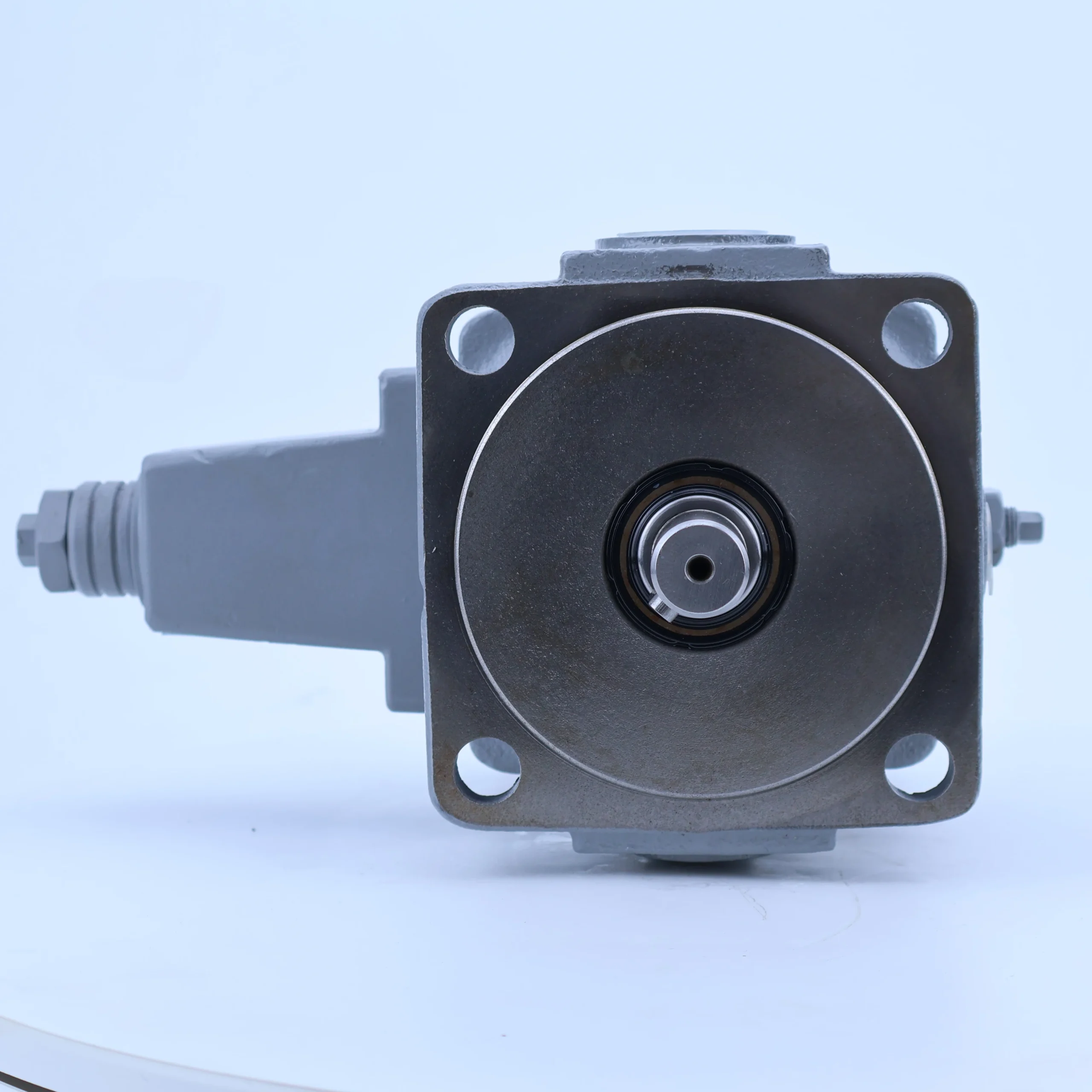
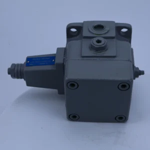
•Structural type: Horizontal installation structure, with the pump body integrated with a pressure compensation variable mechanism (including control piston, regulating spring and feedback valve core); The rotor rotates synchronously with the input shaft by key connection, and the stator can slide axially along the guide rail of the pump body to change the eccentricity. The distribution plate adopts a bimetallic composite structure, integrating an oil suction/pressure oil window and an unloading trough.
•Core materials: The rotor is made of alloy structural steel (40Cr, quenched and tempered, hardness HB280-320), and the blades are made of alloy tool steel (W6Mo5Cr4V2, quenched, hardness HRC55-60, surface chromium plating thickness 0.01-0.02mm). The stator is made of ductile iron (QT600-3, aged treatment, inner surface roughness Ra0.4 μm). The pump body is made of gray cast iron (HT250, aged treatment, tensile strength ≥250 MPa).
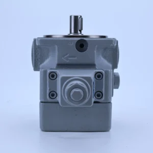
•Connection specifications: The diameter of the oil suction port (S port) is Φ 40mm, and the diameter of the oil pressure port (P port) is Φ 32mm. Both adopt metric fine thread (S port M42×2, P port M36×2). The installation method is flange installation, compatible with ISO 7005-2 standard flange. The flange hole diameter is Φ 14mm, and the installation center distance is 80× 120mm. The input shaft is splined (module 2.5, number of teeth 14, pressure Angle 20°).
3. Medium and Environmental requirements
•Medium requirements: It is recommended to use L-HM 46 or L-HM 68 anti-wear hydraulic oil. For low-temperature environments (below -10℃), L-HV 68 hydraulic oil should be selected. The kinematic viscosity range of the oil is 15-400 mm²/s (the optimal working viscosity is 30-100 mm²/s), the acid value is ≤0.1 mgKOH/g, and the moisture content is ≤0.1%.
•Cleanliness standard: The oil cleanliness should reach ISO 4406 18/15 grade (NAS 8 grade). A 60 μm coarse filter (filtration accuracy 60 μm, dirt-holding capacity ≥30 g) must be installed at the front end of the oil suction port. It is recommended to install a 10 μm fine filter (rated pressure ≥ 31.5MPa) at the oil pressure port.
•Environmental parameters: Operating environment temperature -10℃ to 70℃, relative humidity ≤95% (no condensation); It can adapt to the working conditions with vibration acceleration ≤10 m/s² (frequency 10-500 Hz), and has a protection grade of IP54 (for the main body of the pump). It should avoid long-term exposure to environments with dust concentration > 5 mg/m³ or corrosive gases.
Ii. Working Principle
This pump is a pressure-compensated variable vane pump. Through the core mechanism of “rotor rotation – change in sealed volume to achieve oil suction and discharge – pressure feedback to adjust eccentricity and control flow”, it realizes the adaptive regulation of the flow rate in the hydraulic system. The specific working process is as follows:
1. Basic processes of oil absorption and oil pressure
The motor drives the input shaft to rotate the rotor at high speed (500-1800 r/min). Under the dual action of centrifugal force and root pressure oil, the blades in the rotor slots closely adhere to the inner surface of the stator. Due to the initial eccentricity between the rotor and the stator (maximum eccentricity e_max=3 mm), when the blades rotate with the rotor to the lower half of the stator (oil suction zone), the sealed volume formed by adjacent blades, the outer circle of the rotor, the inner surface of the stator and the distribution plate gradually increases, the pressure inside the volume decreases to form a vacuum, and the hydraulic oil is sucked into the sealed volume through the oil suction window of the distribution plate. When the blades rotate to the upper half of the stator (the oil pressure zone), the sealed volume gradually decreases along with the contour of the stator’s inner surface. The oil is squeezed and pressurized, and then output to the hydraulic system through the oil pressure window of the distribution plate. Each time the rotor rotates once, it completes one oil suction and pressure process, achieving continuous oil supply.
2. Pressure compensation variable regulation mechanism
The pressure compensation mechanism integrated in the pump body is the core of flow regulation, which realizes the adaptive adjustment of eccentricity through “pressure-force balance”.
•Low-load high-flow mode: When the system load is low (pressure < set variable pressure), the force exerted by the pressure oil at the oil pressure port on the control piston through the feedback channel is less than the preload of the regulating spring (the preload of the spring corresponds to the set variable pressure). At this time, the stator maintains the maximum eccentricity state under the thrust of the spring, and the change in the sealed volume is the greatest. The pump outputs the maximum flow rate (rated flow rate 37.5 L/min), meeting the rapid action requirements of the system (such as rapid mold closing of injection molding machines).
•High-pressure low-flow mode: When the system load increases and the pressure at the oil pressure port reaches the set variable pressure (adjustable from 8 to 21 MPa), the thrust of the pressure oil on the control piston is balanced with the preload of the spring. When the pressure continues to rise beyond the set value, the thrust is greater than the spring force, pushing the control piston to move the stator along the guide rail in the direction of reducing the eccentricity. When the eccentricity between the stator and rotor decreases, the change in the sealed volume also reduces, and the output flow of the pump linearly decreases until the flow can only compensate for system leakage (minimum flow ≤3 L/min), achieving “high-pressure flow limiting”, avoiding system overload and reducing energy loss.
•Pressure unloading protection: When the system pressure reaches the maximum working pressure of 25 MPa, the variable mechanism pushes the stator to make the eccentricity approach zero, and the flow drops sharply to the leakage level. The pump is in an unloading state to prevent damage to the pump body and system components due to overpressure.
3. Flow distribution and stability guarantee
The distribution plate adopts an optimized unloading groove design. A transition unloading area is set between the oil suction window and the oil pressure window to prevent direct impact between high-pressure oil and low-pressure oil, which may cause pressure pulsation. At the same time, low-pressure oil is always passed through the root of the blade to ensure that the blade closely adheres to the inner surface of the stator throughout the entire rotation cycle, reducing the phenomenon of trapped oil. These designs ensure that the pump’s pressure pulsation is ≤±0.3 MPa and the operating noise is ≤75 dB (under the rated condition of 1500 r/min), enhancing the stability of the system operation.
Iii. Product Features and Advantages
1. The pressure is self-adaptive and adjustable, achieving remarkable energy-saving effects
The pressure compensation variable mechanism is adopted, and the flow rate can be automatically adjusted according to the system pressure (within the range of 10% to 100%). When the system is in a pressure-holding or low-speed condition, the flow rate automatically drops to the leakage compensation level, which saves 20% to 30% energy compared with the fixed displacement vane pump. The variable pressure can be set steplessly within the range of 8-21 MPa by adjusting the screw, adapting to different load requirements and avoiding the throttling loss of the relief valve in traditional systems.
2. High-pressure resistance, wear resistance, and outstanding reliability
The blades are made of W6Mo5Cr4V2 high-speed steel and undergo quenching treatment. The surface is chrome-plated to enhance wear resistance. Combined with QT600-3 ductile iron stator (with finely ground inner surface), there is no abnormal wear at a maximum pressure of 25 MPa. Under rated working conditions, the fault-free operation life reaches 8,000 hours. The rotor is treated with 40Cr quenching and tempering, which increases the impact strength by 40% and can adapt to heavy-load impact scenarios such as construction machinery.
3. Low noise and low pulsation, smooth operation
The optimized distribution plate unloading groove structure and blade arc transition design effectively suppress the trapped oil phenomenon and pressure shock. The operating noise is ≤75 dB (1500 r/min), which is 5-8 dB lower than that of ordinary variable vane pumps. The pressure pulsation is ≤±0.3 MPa, providing a stable power source for precision hydraulic systems (such as machine tool feed systems) and enhancing processing accuracy.
4. Wide speed adaptation, convenient for installation and maintenance
The speed adaptation range is 500-1800 r/min, and it can be directly matched with 4-stage and 6-stage standard motors without the need for additional reduction devices. It adopts a cartridge pump core structure. When disassembling, only the front flange needs to be removed to take out the rotor-stator assembly. The replacement time of vulnerable parts such as blades and distribution plates is ≤1 hour, and the maintenance cost is reduced by 30% compared with the integral structure.
5. It has strong anti-pollution ability and good environmental adaptability
The root of the blade adopts a self-cleaning oil passage design, which can discharge impurity particles into the return oil chamber. Combined with the 60 μm oil suction filtration requirement, it can still work normally under ISO 4406 18/15 grade cleanliness, and the anti-pollution ability is increased by 20% compared with ordinary vane pumps. The pump body is made of HT250 cast iron and has undergone aging treatment, which can adapt to a wide temperature range from -10℃ to 70℃ and is suitable for industrial scenarios in various regions.
Iv. Usage Functions and Purposes
1. Core usage functions
•
Flow adaptive regulation: Automatically changes the output flow (3.75-37.5 L/min) according to the system pressure. At low loads, it outputs a large flow to achieve rapid action, and at high loads, it outputs a small flow to maintain pressure. It is suitable for compound working conditions such as “fast feed – working feed – pressure holding”, without the need for additional flow control valves.
•
Pressure limit protection: The maximum pressure limit (25 MPa) is achieved through a variable mechanism. When the system pressure exceeds the limit, it automatically unloads, replacing the safety protection function of traditional relief valves and simplifying the system circuit design.
•
Smooth power supply: Low pressure pulsation (≤±0.3 MPa) and low noise characteristics provide smooth power for the hydraulic system, reduce the vibration of the actuator caused by pressure fluctuations, and enhance the stability of equipment operation.
•
Wide operating condition adaptability: The wide speed range of 500-1800 r/min can be matched with motors of different powers. By replacing the regulating springs of different stiffness, a variable pressure setting of 8-21 MPa can be achieved, making it suitable for multiple load scenarios.
2. Main application fields
•
Machine tool equipment: The feed system of horizontal machining centers, the tool turret drive system of CNC lathes, and the reciprocating motion system of the worktable of grinding machines, all meet the requirements of precision machining for stability and flow regulation.
•
Plastic machinery: The clamping, injection and ejection systems of 30-50 ton injection molding machines, and the parison forming systems of blow molding machines, achieve efficient switching between “fast clamping – slow injection – pressure holding” through self-adaptive flow regulation.
•
Construction machinery: The lifting system of small loaders, the lifting and tilting system of forklifts, and the auxiliary actions of hydraulic excavators (bulldozers, rotary platforms), suitable for intermittent load change working conditions.
•
Light industry and metallurgical equipment: The pressing system of the fully automatic tablet press, the cutting drive system of the carton forming machine, and the transmission system of the small metallurgical roller conveyor provide energy-saving power sources for medium and low pressure loads.
V. Applicable Machines and Scenarios
1. Adapt to the core machine
•Machine tool equipment: XH714 vertical machining center, CK6150 CNC lathe, M1432 cylindrical grinding machine.
•Plastic machinery: 30-ton horizontal injection molding machine, 500×500mm fully automatic blow molding machine, small hollow molding machine.
•Construction machinery: 1-3 ton small loaders, 3-5 ton internal combustion forklifts, 6-8 ton small excavators.
•Specialized equipment: 100-ton fully automatic tablet press, high-speed carton cutting machine, small metallurgical roller conveyor transmission system.
2. Typical application scenarios
•
Injection molding machine mold closing – injection molding operation: During the operation of a 30-ton injection molding machine, the system pressure is low (5-8 MPa) during the mold closing stage, and the pump is in the maximum eccentricity state, outputting a large flow rate of 37.5 L/min to achieve rapid mold closing (mold closing time ≤2 seconds). During the injection molding stage, when the load increases (pressure 15-20 MPa), the pump automatically reduces the eccentricity, and the flow rate drops to 5-10 L/min, maintaining a stable injection molding pressure. During the pressure-holding stage, the pressure reaches 21 MPa, and the flow rate drops to 3 L/min to compensate for leakage. The entire process achieves an energy-saving rate of over 25%.
•
Feed operation of the machining center: When the XH714 machining center moves rapidly, the system pressure is 6-8 MPa, and the pump outputs a flow rate of 30 L/min to achieve rapid positioning of the worktable (moving speed 10 m/min). During the cutting process, the pressure is raised to 12-18 MPa, and the flow rate is automatically adjusted to 8-15 L/min. Combined with the servo valve, the feed speed can be steplessly adjusted from 0.01 to 1 m/min, and the processing accuracy is improved to ±0.005 mm.
•Forklift lifting operation: When a 3-ton forklift is lifted without load, the system pressure is 8-10 MPa, the pump outputs a flow rate of 37.5 L/min, and the forklift speed is 0.5 m/s. When lifted under full load (3 tons), the pressure rises to 18-20 MPa, the flow rate drops to 10-15 L/min, and the lifting speed steadily decreases to 0.15 m/s, avoiding sudden speed drops caused by excessive load and enhancing operational safety.
Six. Similar models
1. Alternative models of the same series
•1PV2V3-41/20RA0MC100A1: The structure is exactly the same as the original model. The core differences are the rated displacement of 20 mL/r (flow rate of 30 L/min at 1500 r/min), the maximum working pressure of 25 MPa, and the variable pressure adjustment range of 6-18 MPa. The installation dimensions and connection specifications are fully compatible, suitable for medium and small flow demand scenarios (such as small machining centers, 20-ton injection molding machines), and the cost is 15% lower than that of the original model.
•1PV2V3-41/30RA0MC100A1: Large displacement model of the same series, rated displacement 30 mL/r (flow rate 45 L/min at 1500 r/min), maximum working pressure 25 MPa, variable pressure adjustment range 10-21 MPa. The structural form, material and protection level are consistent with the original model, suitable for high-flow scenarios (such as 50-ton injection molding machines and 4-ton loaders), but the cost is 20% higher than that of the original model.
2. Cross-series alternative models
•PV2R1-25-F-RAA-40: Fixed displacement vane pump, rated displacement 25 mL/r, rated pressure 21 MPa, volumetric efficiency ≥90%. The structure is simple and variable, with a cost 30% lower than the original model. It is suitable for scenarios with stable flow requirements (such as conveyor belt drive), but it requires additional configuration of relief valves and throttle valves to achieve pressure and flow control.
•VVP40-25-150: Load-sensitive variable vane pump, rated displacement 25 mL/r, rated pressure 25 MPa, response time ≤50 ms. The direct feedback mechanism of load pressure is adopted, and the energy-saving effect is relatively good
-1PV1V2-35/25RA0MC100A1: Single-acting variable vane pump, rated displacement 25 mL/r, rated pressure 21 MPa, volume 20% smaller than the original model. It adopts a simplified variable mechanism, with slightly lower adjustment accuracy (flow fluctuation ±3%), suitable for scenarios with limited installation space (such as small forklifts), and the cost is 10% lower than that of the original model.
Vii. Precautions for Use
1. Oil and fluid management norms
Strictly select L-HM 46 or L-HV 68 anti-wear hydraulic oil. It is strictly prohibited to mix oils of different grades. The oil of the new pump must be replaced after its first 500 hours of operation. Subsequently, it should be replaced every 2,000 hours. Before changing the oil, the oil tank and pipelines should be flushed with new oil of the same grade (the flushing oil volume should be ≥ 1.5 times the system volume).
When the pressure difference of the oil suction filter exceeds 0.1 MPa, the filter element should be replaced immediately. The moisture content (≤0.1%) and viscosity (15-400 mm²/s) of the oil should be tested monthly. If they exceed the standards, vacuum dehydration or oil replacement treatment should be adopted. It is strictly prohibited to use oil that has been emulsified, deteriorated or contains metal impurities to prevent blade jamming or stator wear.
2. Installation and commissioning requirements
When installing, the coaxiality error between the pump shaft and the motor shaft should be no more than 0.1mm (for rigid connection) or no more than 0.3mm (for elastic connection), and the flatness of the installation flange surface should be no more than 0.05mm /m to avoid premature bearing damage caused by coaxiality deviation. The height from the oil suction port to the oil surface of the oil tank shall be no more than 0.5m, and the diameter of the oil suction pipeline shall be no less than Φ 40mm to reduce the oil suction resistance and prevent cavitation.
Before the first start-up, the pump body should be filled with hydraulic oil (added through the oil filling port), and the input shaft should be manually turned 3 to 5 times to ensure that the blades and stator are fully lubricated. When starting, it is necessary to run the pump without load for 5 to 10 minutes (at a speed of 1000 r/min), and check if there is any abnormal noise or leakage in the pump body. After the oil temperature rises above 30℃, gradually load it to the rated pressure.
Variable pressure adjustment should be carried out through a dedicated adjusting screw. Turning the screw clockwise increases the set pressure, while turning it counterclockwise decreases the pressure. When adjusting, load gradually. After each adjustment (rotate 1/4 turn), stabilize for 30 seconds until the system pressure reaches the design requirement (it is recommended that the set value does not exceed 90% of the rated pressure).
3. Operation monitoring and maintenance
During operation, real-time monitoring of the pump body temperature (normal ≤65℃, maximum ≤70℃), inlet and outlet pressures (P port ≤21 MPa, suction port vacuum ≤0.02 MPa), and operating noise (≤75 dB) is conducted. If a sudden temperature rise of ≥10℃, abnormal pressure fluctuations or abnormal noises are detected, the machine should be immediately shut down for inspection. The key points to check are the cleanliness of the oil, the jamming of the blades or the wear of the distribution plate.
Regular maintenance should be carried out every 1500 hours: clean the oil suction/pressure oil filter, check the wear of the blades (replace if the wear at the top of the blade is greater than 0.1mm), and measure the roundness of the inner surface of the stator (repair if the roundness error is greater than 0.02mm). Replace the blades, seals and adjusting springs every 3,000 hours to ensure the sensitivity of the variable mechanism.
Maintenance should be carried out in a clean environment. The disassembled blades, rotors and other parts should be cleaned with aviation kerosene. When reassembling, apply a small amount of hydraulic oil to the blade grooves for lubrication. When installing the distribution plate, it is necessary to ensure that the positioning pins are aligned to avoid installing it in reverse, which may cause pressure shock and damage the pump body.
4. Storage and Idle protection
When stored for a long time, the oil suction port and the oil pressure port should be blocked with plugs. Inject L-TSA 46 anti-rust oil into the pump body (the oil injection volume should be 80% of the pump body volume), and place it in a dry and well-ventilated area (temperature 5-35℃, humidity ≤60%). Manually rotate the input shaft 2 times a month to prevent the blades from adhering to the stator and the metal parts from rusting.
Before being put into use after being idle for more than 6 months, the anti-rust oil needs to be drained, and the pump body should be flushed with L-HM 46 hydraulic oil three times. After each flushing, run the pump without load for 5 minutes. After installation, gradually load to 50%, 75%, and 100% of the rated pressure. Run each stage for 10 minutes. After confirming that the flow rate and pressure are stable and there is no leakage, put it into formal use.


