


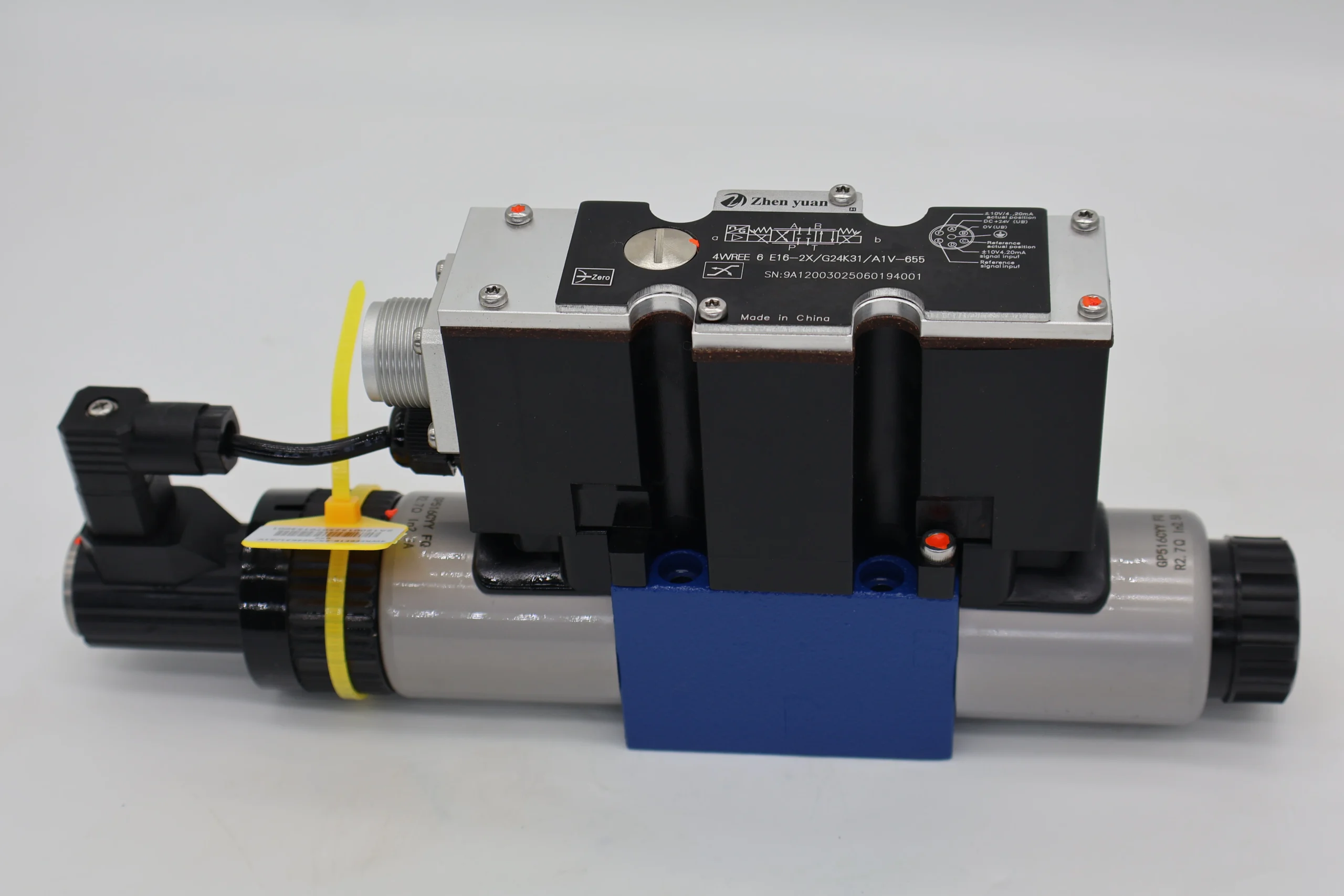
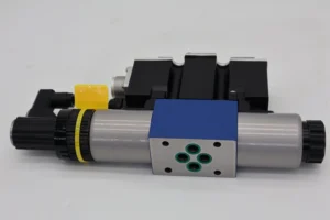

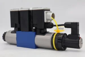


4WREE10 4WREE 4WREE6 Pressure Control Hydraulic Valve R900950342 4WREE6E16-23/G24K31/A1V-655 Proportional Directional Valve
Core performance parameters
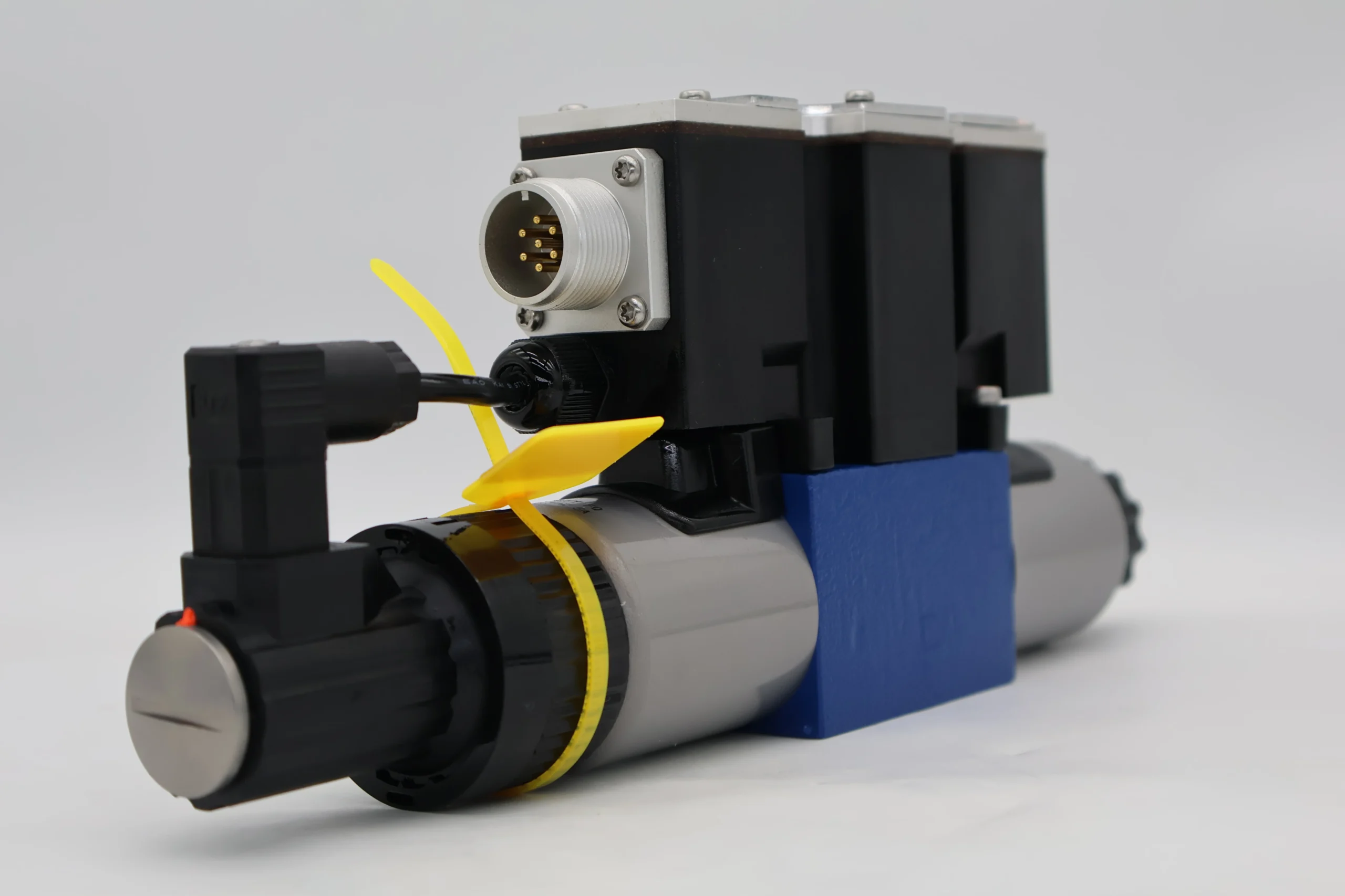
– Valve type: Direct-acting proportional directional control valve, with built-in amplifier and position sensor, four-way structure (P for oil inlet, A/B working oil port, T for oil return), supports proportional control of flow and direction, suitable for small and medium-sized high-pressure hydraulic systems.
– Pressure and flow parameters: Rated working pressure 31.5 MPa (P port), 21 MPa (T port); Rated flow rate: 16 L/min (at a pressure difference of 1 MPa), flow regulation range: 0-16 L/min. Control accuracy: Flow repeatability accuracy ≤0.05%, hysteresis ≤0.1%.
– Control and response parameters: Control voltage 24V DC, command signal supports ± 10V voltage or 4-20mA current; The response time of the valve core is ≤50 ms, and the median alignment accuracy is ±0.01 mm. The built-in position sensor enables closed-loop control.
– Operating characteristics: Working oil temperature -20℃ to 70℃; The pressure loss during continuous operation is ≤0.5 MPa. With a protection grade of IP65, it is suitable for industrial environments with a lot of dust and humidity.
2. Structure and connection parameters
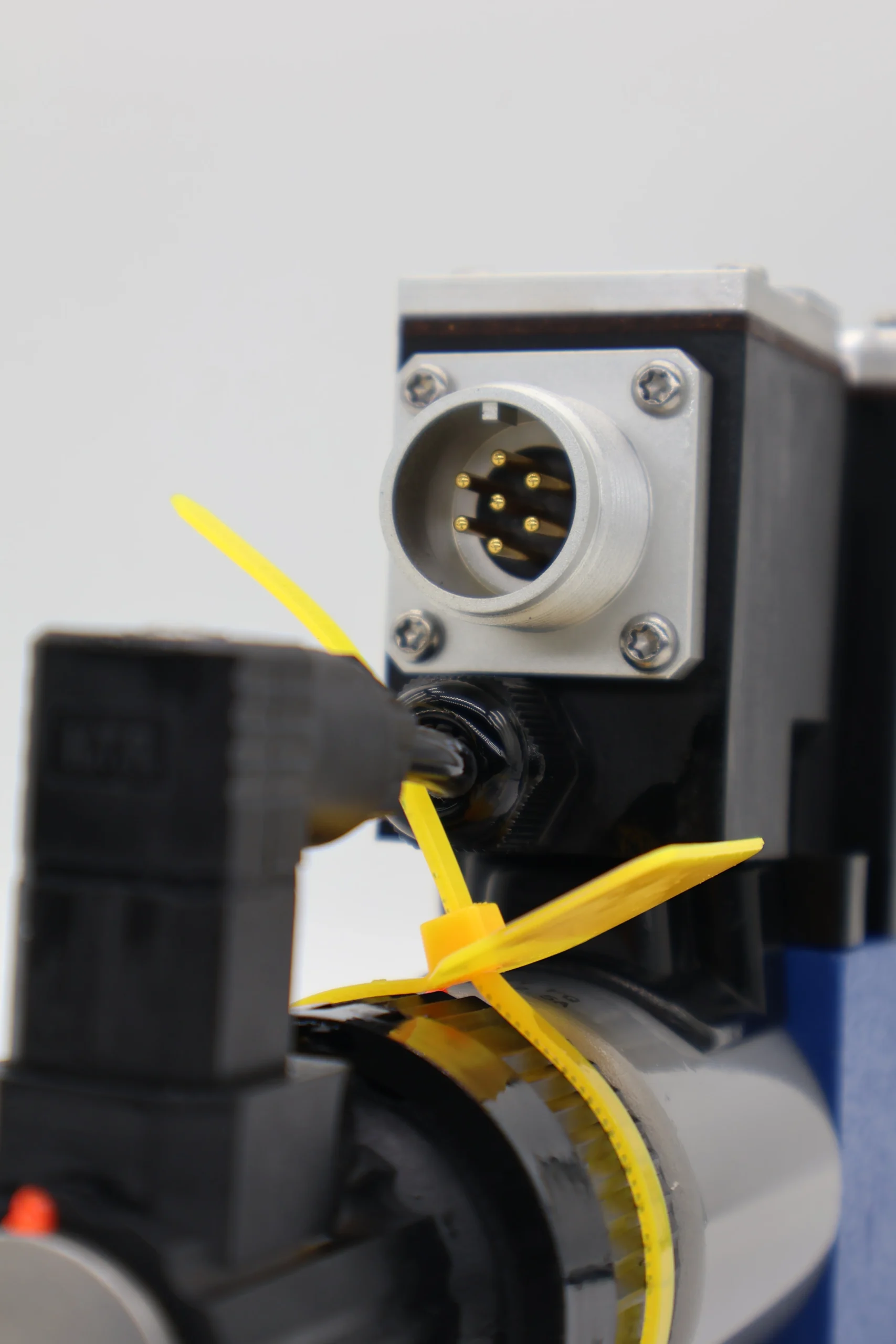
– Structural type: Integrated valve body, centering spring, precision valve core, bidirectional proportional electromagnet, built-in amplifier and position sensor; It adopts fluororubber sealing, with the valve core made of stainless steel and the valve body made of alloy cast iron.
– Connection specification: The oil port connection is threaded (all P/A/B/T ports are G1/4″). Electrical connection is DIN EN 175201-804 standard socket; The installation method is in any direction (horizontal installation is preferred), and the weight is approximately 2.4 kg.Ii. Working Principle
This valve is a direct-acting proportional directional control valve. Its core achieves precise control over the flow and direction of the hydraulic system through a proportional conversion mechanism of “electrical signal – mechanical displacement – fluid flow regulation”. The specific process is as follows:
1. Median initial state
When neither side of the proportional electromagnets is energized, the centering spring stabilizes the valve core in the neutral position. At this time, the P port (oil inlet), A/B port (working oil port), and T port (return oil) are all in a closed state, with no liquid flowing through, and the actuator remains stationary.
2. Direction and flow control process
– Single-sided power-on control: If the electromagnet on the right side (controlling port B) is energized, the built-in amplifier converts the input electrical signal into a proportional electromagnetic force, pushing the valve core to move to the left. The moving distance is proportional to the strength of the electrical signal. At this point, port P forms A passage with Port A and Port B with Port T. High-pressure oil enters the actuator through port A to drive the action, and the return oil is discharged through ports B and T. The flow rate is determined by the opening degree of the throttle port formed by the displacement of the valve core.
– Reverse control: If the electromagnet on the left (controlling port A) is energized, the valve core moves to the right, connecting port P with port B and Port A with port T, and the actuator operates in reverse. When the electrical signal weakens, the valve core resets under the action of the centering spring, and the flow rate decreases proportionally accordingly.
3. Closed-loop feedback guarantee
The position sensor built into the valve core detects the displacement of the valve core in real time, feeds the signal back to the built-in amplifier, and compares and calibrates it with the input command signal to ensure that the displacement of the valve core precisely matches the command requirements, avoiding flow deviation caused by load changes or pressure fluctuations.
Iii. Product Features and Advantages
– Precise and stable proportional control: Adopting the “electrical signal – displacement” proportional conversion design, the flow repeatability accuracy is ≤0.05%, the hysteresis is ≤0.1%, and it can achieve stepless adjustment of the actuator speed. The closed-loop feedback mechanism ensures that the flow is not affected by fluctuations in load pressure, making it suitable for precise control scenarios.
– High integration and easy deployment: Built-in amplifier and position sensor, no need for external control module, simplifying system wiring and layout; The standardized socket and threaded connection design reduce the installation and commissioning time by 40% compared with the split structure, meeting the demand for rapid integration.
– Strong anti-pollution and reliability: The valve core adopts a precision grinding process and is combined with fluororubber sealing parts. The oil cleanliness requirement is only ISO 4406 16/13 grade (NAS 9 grade), and the anti-pollution ability is 50% higher than that of servo valves. The fault-free operating life under rated conditions is ≥ 8,000 hours.
– Quick response to dynamic scenarios: The valve core response time is ≤50 ms, allowing for rapid switching of the actuator’s action direction and speed. The median alignment accuracy is ± 0.01mm. It has a small impact during action switching and is suitable for high-frequency start-stop automated operations.
Iv. Usage Functions and Purposes
1. Core usage functions
– Flow direction integrated control: A single valve realizes the dual functions of “flow size adjustment + action direction switching”, replacing the traditional combination of “directional control valve + flow valve”, reducing the number of system components by 30% and lowering the risk of leakage.
– Precise process regulation: The flow rate is steplessly regulated through 0-10V / 4-20mA electrical signals, which is compatible with the multi-stage speed control of the actuator, such as the mold closing speed regulation of injection molding machines and the feed speed control of machine tools.
Dynamic load adaptation: The closed-loop feedback mechanism compensates in real time for changes in load pressure, ensuring stable flow within ±20% of load fluctuations, avoiding sudden changes in actuator speed, and improving operation accuracy.
2. Main application fields
In the field of construction machinery, It is suitable for the control of working devices (buckets, booms) of 10-30 ton wheel loaders and small excavators, achieving smooth adjustment of action speed. Precise speed regulation of the luffing mechanism of small cranes.
– Industrial equipment field: Small and medium-sized injection molding machines (mold closing, injection circuits), 50-200 ton hydraulic presses (main cylinder action control), auxiliary roller drive for metallurgical equipment, suitable for precision manufacturing scenarios.
– Automated production lines: Control of the telescopic/rotational movements of robot handling mechanisms, and control of the opening and closing of hydraulic fixtures on automated assembly lines, suitable for high-frequency and high-precision automated operations.
V. Applicable Machines and Scenarios
1. Adapt to the core machine
– Construction machinery: 10-30 ton wheel loaders, 5-15 ton small excavators, 8-20 ton truck cranes.
– Industrial equipment: 100-500 ton medium and small-sized hydraulic presses, 300-800 ton injection molding machines, metallurgical auxiliary roller conveyor equipment.
– Automation equipment: Hydraulic actuators for industrial robots, hydraulic fixtures for automated assembly lines, drive systems for small conveying equipment.
2. Typical application scenarios
– Loader operation scenario: As the main valve for controlling the bucket of a 15-ton loader, it controls the displacement of the valve core through the electrical signal output by the control lever, achieving the action switch of “quick lowering – slow loading – smooth lifting” of the bucket. The flow regulation accuracy ensures that no material is spilled during loading, and the operation efficiency is increased by 20%.
– Injection molding machine forming scenario: It is used in the mold closing circuit of 500-ton injection molding machines. The electrical signal proportional control of the mold closing speed seamlessly switches from fast mold closing (16 L/min) to low-pressure mold protection (3 L/min), avoiding mold collision and increasing the qualification rate of formed parts by 15%.
– Automated assembly scenario: Compatible with robot hydraulic fixtures, a 40ms rapid response enables the fixture to perform the actions of “quick opening – slow clamping – pressure holding”, with a repeat positioning accuracy of ± 0.02mm, meeting the assembly requirements of precision parts.
Six. Similar models
1. Alternative models of the same series
-4WREE6E8-23 /G24K31/A1V-655: Small flow model with the same structure, rated flow of 8 L/min, consistent pressure parameters, suitable for micro hydraulic systems (such as small fixtures), and 25% lower cost than the original model.
-4WREE6E32-23 /G24K31/A1V-655: A high-flow model in the same series, with a rated flow rate of 32 L/min and the same pressure parameters. It is suitable for medium and large-sized equipment (such as 30-ton excavators), but the cost is 30% higher than that of the original model.
2. Cross-series alternative models
-4WRE6E16-23 /G24K4/A1V-655: Model without built-in amplifier, requires external amplifier, has a more compact structure, is suitable for scenarios with limited installation space, and has a cost reduction of 18%.
-4WREE10E25-23 /G24K31/A1V-655: Large diameter model (diameter 10mm), rated flow 25 L/min, consistent pressure parameters, suitable for large flow systems (such as large presses), with a 40% higher cost.
-4WREE6Y16-23 /G24K31/A1V-655: The median function can be of different models (Y-type median, A/B port through T port), suitable for systems requiring median unloading (such as hydraulic motor circuits), with the cost remaining the same.
Vii. Precautions for Use
1. Medium management
– Compatible with L-HM 46/68 anti-wear hydraulic oil. It is strictly prohibited to mix different grades of oil. The cleanliness of the oil should reach ISO 4406 16/13 grade (NAS 9 grade). A 5 μm fine filter must be installed at the oil inlet. The filter should be replaced immediately when the pressure difference of the filter is greater than 0.08 MPa.
– Test the moisture content of the oil (≤0.03%) monthly and take samples to test the cleanliness quarterly. When emulsification, discoloration or presence of metal debris in the oil is detected, immediately stop the machine, change the oil and flush the inner cavity of the valve body to prevent the valve core from getting stuck.
2. Installation and commissioning
When installing, confirm the oil port markings (P in, A/B working, T back), and it is strictly forbidden to connect them in reverse. Electrical wiring should distinguish between the positive and negative poles of the power supply (24V DC), and the sockets should be sealed properly to prevent oil stains from entering. The protection level should be maintained at IP65.
Before commissioning, flush the pipeline with low-pressure oil (2-3 MPa) to prevent installation impurities from entering the valve body. After power-on, perform the neutral calibration first to ensure that the valve core is in the neutral position when there is no signal. During the test, gradually increase the electrical signal to check the smoothness of the flow and direction switching. If there is no impact, it is qualified.
3. Operation and Maintenance
During operation, real-time monitoring of valve body temperature rise (normal ≤60℃, maximum ≤70℃), pressure loss and action response is carried out. If there is any lag in operation, flow fluctuation exceeding 5% or abnormal noise, stop the machine immediately for inspection, with a focus on checking for oil contamination or wear of the electromagnet.
Regular maintenance every 6,000 hours: Disassemble and clean the valve core and valve sleeve, and check the fit clearance (replace when > 0.01mm). Replace the sealing parts, recalibrate the position sensor and amplifier to ensure that the control accuracy meets the standards.
It is strictly prohibited to operate under overpressure (P port pressure > 31.5 MPa) or to work at the maximum flow rate for a long time. Avoid frequent and high-frequency commutation (more than 3 times per second) to prevent the electromagnet from overheating and getting damaged.
4. Storage protection
When stored for a long time, use a special plug to seal the oil port and inject anti-rust oil into the valve body. Store in a dry warehouse with a temperature range of 0-40℃ and a humidity of no more than 60%. Avoid direct sunlight and heavy object compression. Power on once every three months (for 10 minutes) to maintain the activity of the electromagnet.
Before being put into use after being idle for more than 12 months, replace the sealing parts and flush the inner cavity. Conduct a 30-minute low-voltage trial run to test the median accuracy and action response. After meeting the standards, connect to the system.


