


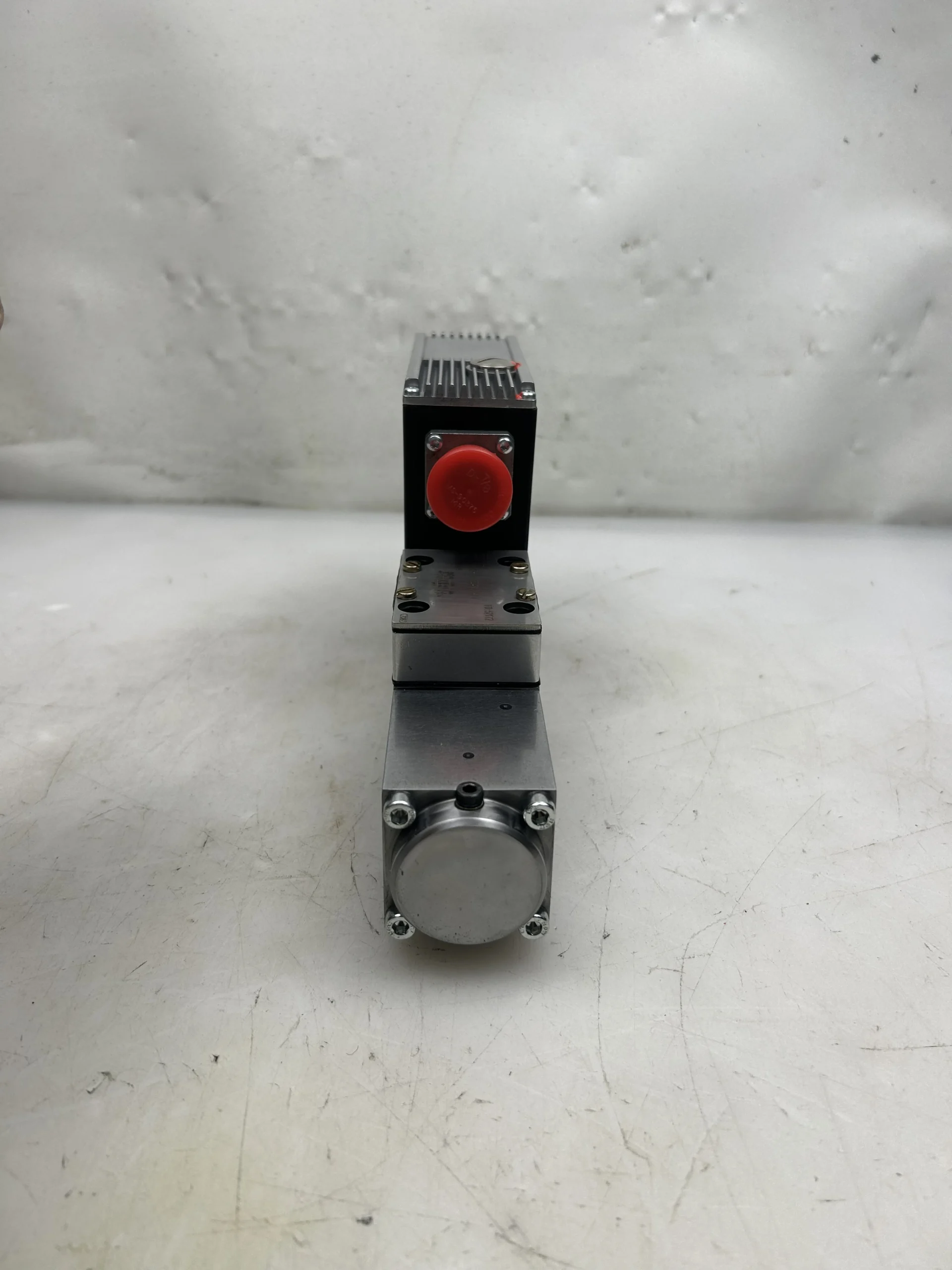

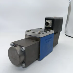
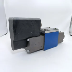
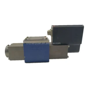
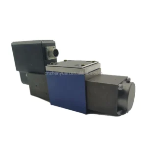
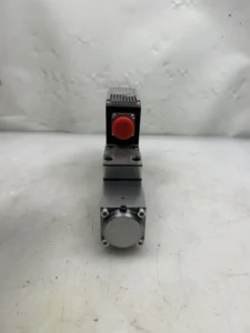

4WRKE 4WRZE 4WRSE 4WRSE6 4WRSE10 Proportional Directional Valves 4WRSE10Q00-32/G24K0/A1V-587 Hydraulic Solenoid Control Valve
Core performance parameters
– Valve type: Electro-hydraulic proportional directional control valve, pilot-operated structure + proportional electromagnet control, suitable for medium and high-pressure proportional flow/pressure control scenarios, supports open-loop/closed-loop control, and can be connected to the hydraulic system to achieve stepless flow regulation.
– Pressure and flow rate: Rated working pressure 31.5 MPa, peak pressure 35 MPa (sustained for ≤3 seconds); Rated flow rate: 60 L/min (under the working condition of 31.5 MPa), flow regulation range: 5-60 L/min (corresponding to control signal: 4-20mA). Back pressure tolerance ≤5 MPa.
– Control performance: The control signal is a DC4-20mA current signal, with a signal resolution of ≤0.1mA. Flow control accuracy: ±1% (at rated flow), pressure control accuracy: ±2%. Response time ≤50ms (when the flow rate increases from 10% to 90%).
– Power and efficiency: The rated voltage of the proportional electromagnet is DC24V, and the rated power is 15W. The total efficiency of the valve group is ≥90% (under rated working conditions), and the internal leakage is ≤0.3 mL/min (at 31.5 MPa).
2. Structure and connection parameters
– Structural type: Two-way cartridge type + pilot control module integrated structure, including main valve (valve core, valve sleeve), proportional electromagnet, displacement sensor (for closed-loop feedback), relief valve (with built-in protection); Supports horizontal/vertical installation, and the installation surface is compatible with the ISO 6264 standard.
– Core material: The main valve body is made of 45 # forged steel (quenched and tempered); The valve core is made of stainless steel 304 (surface hardened treatment, hardness HRC50-55). The sealing parts are made of high-pressure resistant fluororubber (with a temperature resistance range of -20℃ to 120℃). The core of the proportional electromagnet is DT4 pure iron.
– Connection specifications: The diameters of the oil inlet (P port), return oil port (T port), and working port (A/B port) are all Φ10mm, and the interface thread is M22×1.5. The control signal interface is an M12 aviation plug. The total weight of the valve assembly is approximately 8 kg, and its external dimensions (length × width × height) ≈200×120×150mm.
3. Medium and Environmental requirements
– Medium requirements: It is recommended to use L-HM 46/68 anti-wear hydraulic oil. For low-temperature environments (below -30℃), L-HV 46 anti-wear hydraulic oil is selected. The kinematic viscosity of the oil is 15-400 mm²/s, and the moisture content is no more than 0.05%. It is strictly prohibited to mix oils of different grades.
– Cleanliness standard: The oil cleanliness must reach ISO 4406 16/13 grade. The system must be equipped with a 5 μm fine filter, and a 100 μm coarse filter must be placed in front of the oil suction port. The filter pressure difference should be monitored regularly (the fine filter pressure difference should be replaced when it is greater than 0.5 MPa).
– Environmental parameters: Operating environment temperature -20℃ to 85℃, relative humidity ≤95% (short-term condensation is allowed); The protection grade is IP65 (valve body) and IP67 (control plug), suitable for dusty and slightly oily working conditions in construction machinery, industrial hydraulic stations, etc.Ii. Working Principle
This proportional valve is an electro-hydraulic proportional directional control valve. Its core achieves precise control through a proportional conversion mechanism of “electrical signal – mechanical force – hydraulic flow/pressure”. The specific process is as follows:
1. Basic control process
The controller outputs a DC4-20mA proportional current signal to the proportional electromagnet. The electromagnet generates an electromagnetic force of corresponding magnitude based on the signal strength, driving the valve core of the pilot valve to move and changing the pressure in the pilot oil circuit. The pilot pressure oil acts on the control chamber of the main valve core, driving the main valve core to move along the axis. By changing the flow area between the valve core and the valve sleeve, the flow rate from the oil inlet (P) to the working port (A/B) can be steplessly regulated. When the signal changes in the opposite direction, the valve core moves in the opposite direction, and the flow rate decreases proportionally, achieving precise closed-loop control of the flow rate.
2. Reversing and protection mechanism
– Reversing control: The load reversing is achieved by switching the oil supply direction of ports A/ B. When the proportional solenoid A is energized, the main valve core moves to the left, and the oil from port P enters Port A, while the oil from port B returns to port T. When the electromagnet B is energized, the valve core moves to the right and the oil circuit switches in the reverse direction. The switching response time is ≤80ms.
– Safety protection: Built-in relief valve automatically releases pressure when the system pressure reaches 31.5 MPa to prevent overpressure damage. The displacement sensor collects the position signal of the main valve core in real time and feeds it back to the controller to form a closed-loop control, correcting the flow deviation (deviation ≤1%). The electromagnet is equipped with built-in overcurrent protection and automatically limits the current when it exceeds 2A.
Iii. Product Features and Advantages
– High precision of proportional control: The 4-20mA signal linearly controls the flow with an accuracy of ±1%, enabling stepless adjustment of load speed/force (such as gradual control of injection speed in injection molding machines), which improves the regulation accuracy by 80% compared to ordinary solenoid valves. It is suitable for scenarios with high requirements for control accuracy.
– Strong adaptability to medium and high pressure and large flow rate: With a rated pressure of 31.5MPa and a flow rate of 60 L/min, it is suitable for medium power hydraulic systems. It supports the coordinated proportional control of dual actuators (such as the combined action of the excavator boom and the bucket arm), and the flow rate fluctuation under full load conditions is ≤2%, ensuring stable operation.
– Excellent closed-loop feedback reliability: The built-in displacement sensor forms a closed-loop control. When load fluctuations cause flow deviations, corrections are completed within 50ms, avoiding the “drift” problem of ordinary proportional valves. Under rated working conditions, the fault-free operating life reaches 15,000 hours, which is 50% longer than that of the open-loop proportional valve.
– High degree of integration: Integrates pilot control, overflow protection, and displacement feedback into one, eliminating the need for additional control modules and reducing system integration costs by 30%. The standardized installation surface is compatible with most hydraulic stations, and there is no need to modify the installation position when replacing ordinary solenoid valves.
– Remarkable energy-saving effect: The flow rate is output proportionally as needed. Under light load, the flow rate drops below 5 L/min, saving 40-50% energy compared to quantitative valves. Closed-loop control reduces pressure loss, lowers the system oil temperature by 10 to 15 degrees Celsius, and extends the service life of the oil and seals.
Iv. Usage Functions and Purposes
1. Core usage functions
– Flow ratio regulation: The output flow is linearly controlled by the current signal (5-60 L/min), achieving stepless adjustment of the load speed (such as gradual change of crane lifting speed, conveyor belt speed regulation), and is suitable for intermittent or continuous variable speed operations.
– Precise reversing control: Quickly switch the direction of the A/B port oil circuit, and in combination with proportional flow regulation, achieve a “soft start” during the reversing process (such as smooth switching of the hydraulic press head lifting), avoiding load shock and protecting the equipment and workpieces.
Closed-loop pressure compensation: When the system pressure fluctuates, the valve core opening is adjusted through the pressure feedback signal to maintain a stable flow rate (such as flow compensation during the pressure-holding stage of an injection molding machine), ensuring the operation accuracy.
– System integration control: Supports seamless connection with controllers such as PLC and touch screens to achieve remote centralized control. It can be connected to bus systems (such as CANopen) and is compatible with multi-valve group collaborative control scenarios (such as multi-station hydraulic control in automated production lines).
2. Main application fields
In the field of construction machinery: 10-25 ton excavator boom/bucket control, small loader lifting speed regulation, crane lifting/luffing ratio control, suitable for precise operation scenarios of compound actions.
– Industrial manufacturing field: Injection/holding pressure control for 500-1500 ton injection molding machines, speed adjustment of hydraulic press heads, proportional drive of material push mechanisms in automated production lines, suitable for high-precision molding and conveying scenarios.
– Special equipment field: Speed regulation of ship deck machinery (anchor winches, winches), proportional control of auxiliary equipment in mines (tunnel boring machine propulsion), hydraulic drive of medical rehabilitation equipment, suitable for smooth speed regulation and precise positioning scenarios.
V. Applicable Machines and Scenarios
1. Adapt to the core machine
– Construction machinery: 10-25 ton crawler excavators, small wheel loaders, 10-15 ton truck cranes.
– Industrial equipment: 500-1500 ton injection molding machines, 500-1000 ton hydraulic presses, hydraulic control modules for automated assembly production lines.
– Special equipment: Small and medium-sized ship anchors, mine boring machines with a diameter of no more than 3 meters, medical rehabilitation hydraulic drive equipment.
2. Typical application scenarios
– Excavator compound action scenario: As a control proportional valve for the 15-ton excavator boom, it receives the 4-20mA signal output by the PLC, linearly adjusts the boom lifting speed (0.1-0.8m /s), and cooperates with the boom movement to achieve precise loading and unloading. Closed-loop control ensures that the speed fluctuation is ≤5% when the load changes, making it suitable for trenching operations in municipal engineering.
Injection control scenarios for injection molding machines: It is equipped with a 1000-ton injection molding machine injection system. During the injection stage, a full flow rate of 60 L/min is output through a 20mA signal to achieve rapid advancement (1.0m /s speed). During the pressure-holding stage, the pressure is reduced to a 4mA signal corresponding to a stable flow rate of 5 L/min. The forming dimensional error of large plastic parts (such as home appliance shells) is ≤0.3%, making it suitable for batch production scenarios.
– Press head speed regulation scenario: Control the action of the 800-ton hydraulic press head. When unloaded, it rapidly descends at a flow rate of 60 L/min (speed of 0.5 m/s). After contacting the workpiece, gradually reduce to 10 L/min through signals for slow pressing to prevent workpiece deformation. It is suitable for the metal sheet stamping forming scenario.
Six. Similar models
1. Alternative models of the same series
-4WRSE8Q00-20 /G24K0/A1V-587: Small bore model of the same structure, bore Φ8mm, rated flow 30L /min, rated pressure 31.5MPa, compatible installation dimensions, suitable for small hydraulic systems (such as micro presses), cost 25% lower than the original model.
-4WRSE12Q00-80 /G24K0/A1V-587: Large-diameter models of the same series, with a diameter of Φ12mm, a rated flow rate of 80L /min, and consistent pressure parameters. It is suitable for 25-30 ton excavators and 1500-ton injection molding machines. The cost is 30% higher than that of the original model.
2. Cross-series alternative models
-4WRSE10Q0-32 /G12K0/A1V-587: Low-voltage model, proportional electromagnet rated voltage DC12V, flow and pressure parameters are the same as the original model, suitable for 12V power supply systems in vehicles (such as small construction machinery), with the same cost.
-4WRSE10Q00-32 /G24K0/A2V-587: An upgraded bus control model that supports CANopen bus communication, replacing traditional current signal control. It is suitable for centralized control scenarios of multiple valve groups (such as automated production lines), and its cost is 40% higher than that of the original model.
-4WRSE10Q00 -32/G24K0/A1V-587-H: High-temperature upgraded model, with the temperature resistance of the sealing parts increased to 150℃. The valve core is coated with ceramic, suitable for high-temperature working conditions in metallurgy, mining, etc. The cost is 35% higher than that of the original model.
Vii. Precautions for Use
1. Oil management
– L-HM 46/68 anti-wear hydraulic oil must be selected. It is strictly prohibited to mix different grades or deteriorated oils. After the new valve has been in operation for 500 hours for the first time, change the oil. Subsequently, change the oil every 1,500 hours. Before changing the oil, thoroughly clean the oil tank, pipelines, and two-stage filters to avoid residual impurities.
Check the oil level and cleanliness every week. Replace the filter element immediately when the pressure difference of the fine filter exceeds 0.5 MPa, and that of the coarse filter exceeds 0.3 MPa. Every month, the moisture content (≤0.05%) and viscosity of the oil should be tested. When emulsification, discoloration or metal debris is found in the oil, the system should be thoroughly cleaned and the oil replaced to prevent the valve core from getting stuck or worn.
2. Installation and commissioning
When installing, ensure that the valve group is closely attached to the installation surface of the hydraulic station (flatness ≤ 0.02mm /m), and the connecting bolts are evenly tightened with a torque of 150 N·m to avoid leakage. The control signal cables should be shielded wires, kept away from the power cables (with a spacing of ≥30cm), to prevent electromagnetic interference.
Before the first commissioning, flush the inner cavity of the valve body with low-pressure oil (2-3 MPa), and manually push the valve core to ensure it is flexible and free of jamming. After the control signal is connected, test the corresponding outputs of 4mA (minimum flow) and 20mA (maximum flow), and calibrate the flow linearity (deviation ≤1%). Set the pressure of the relief valve to 31.5 MPa and test the overpressure relief function.
When debugging the reversing function, continuously switch the A/B port fuel supply 10 times to ensure that the switching response time is ≤80ms, without any lag or shock. During the closed-loop control debugging, simulate the load fluctuation (pressure ±2 MPa) and confirm that the flow correction response time is ≤50ms.
3. Operation and Maintenance
During operation, real-time monitoring of the valve group temperature (normal ≤60℃, maximum ≤85℃), inlet and outlet pressures, and the stability of control signals is carried out. If a sudden temperature rise of ≥15℃, pressure fluctuation > 1 MPa, or abnormal signals are detected, the machine should be immediately shut down to check the oil cleanliness, electromagnet failure, or valve core jamming issues.
– Regular maintenance every 3,000 hours: Replace the seals and filter elements; Check the fit clearance between the valve core and the valve sleeve (replace if it is greater than 0.05mm). Calibrate the displacement sensor and proportional electromagnet to ensure control accuracy; Clean the control plug and apply waterproof grease to prevent poor contact.
Before the long-term shutdown, the valve core should be reset to the center position and the cylinder should be filled with hydraulic oil to prevent rust. Before starting at low temperatures (< -10℃), the oil should be heated to above 10℃ to prevent the sealing parts from hardening or the oil viscosity from being too high, which may cause the valve core to get stuck.
4. Storage protection
When stored for a long time, seal the oil port with a metal plug, inject anti-rust oil (90% of the valve body volume), and put a dust cap on the control plug. Store in a dry and well-ventilated place (0-40℃, humidity ≤60%), avoid direct sunlight and heavy object compression. Check the anti-rust condition monthly.
Before being put into use after being idle for more than 12 months, thoroughly clean the inner cavity of the valve body and replace the sealing parts. Test the flexibility of the valve core with low-pressure oil, connect the control signal to calibrate the flow and pressure parameters, and after confirming there are no abnormalities, connect it to the system for operation.


