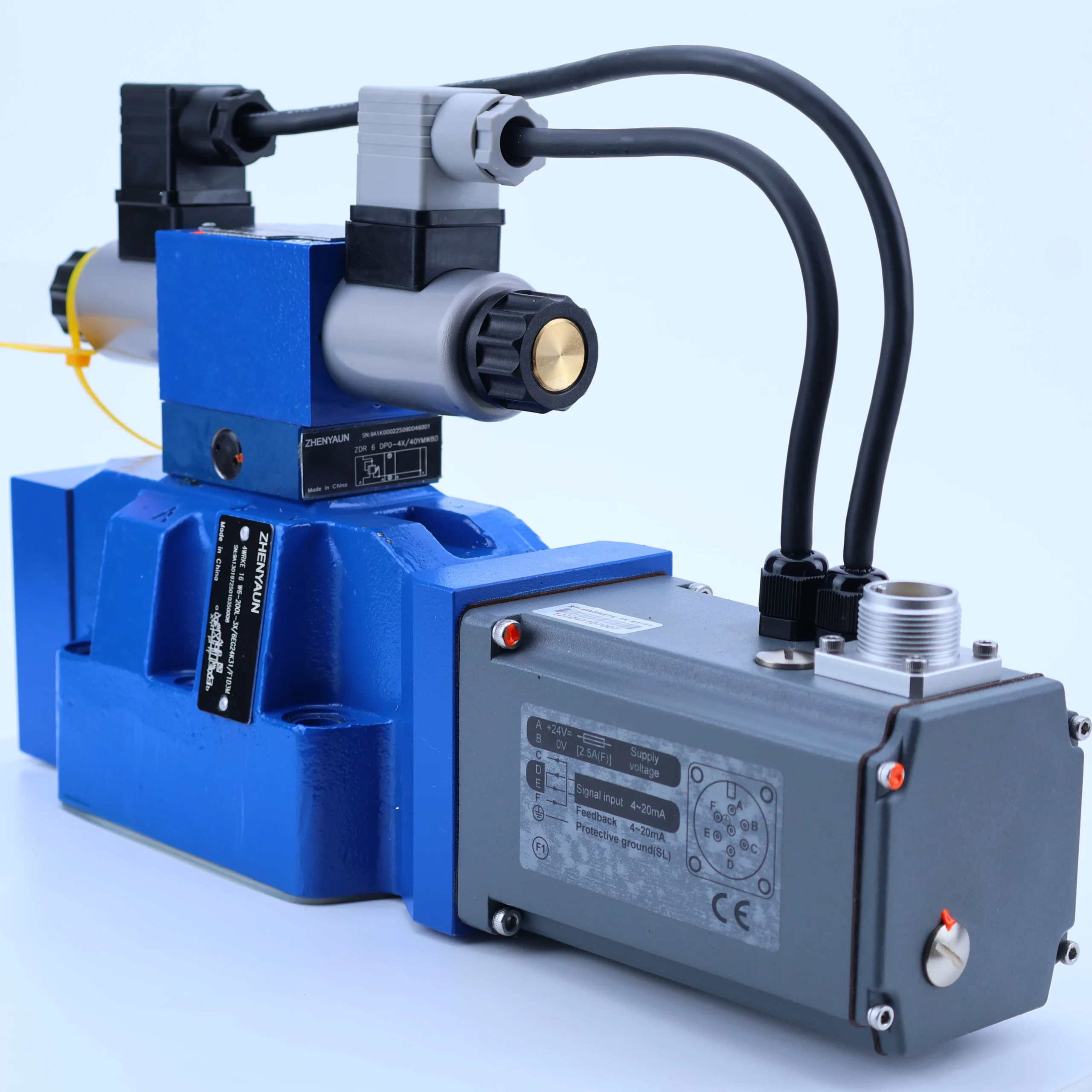

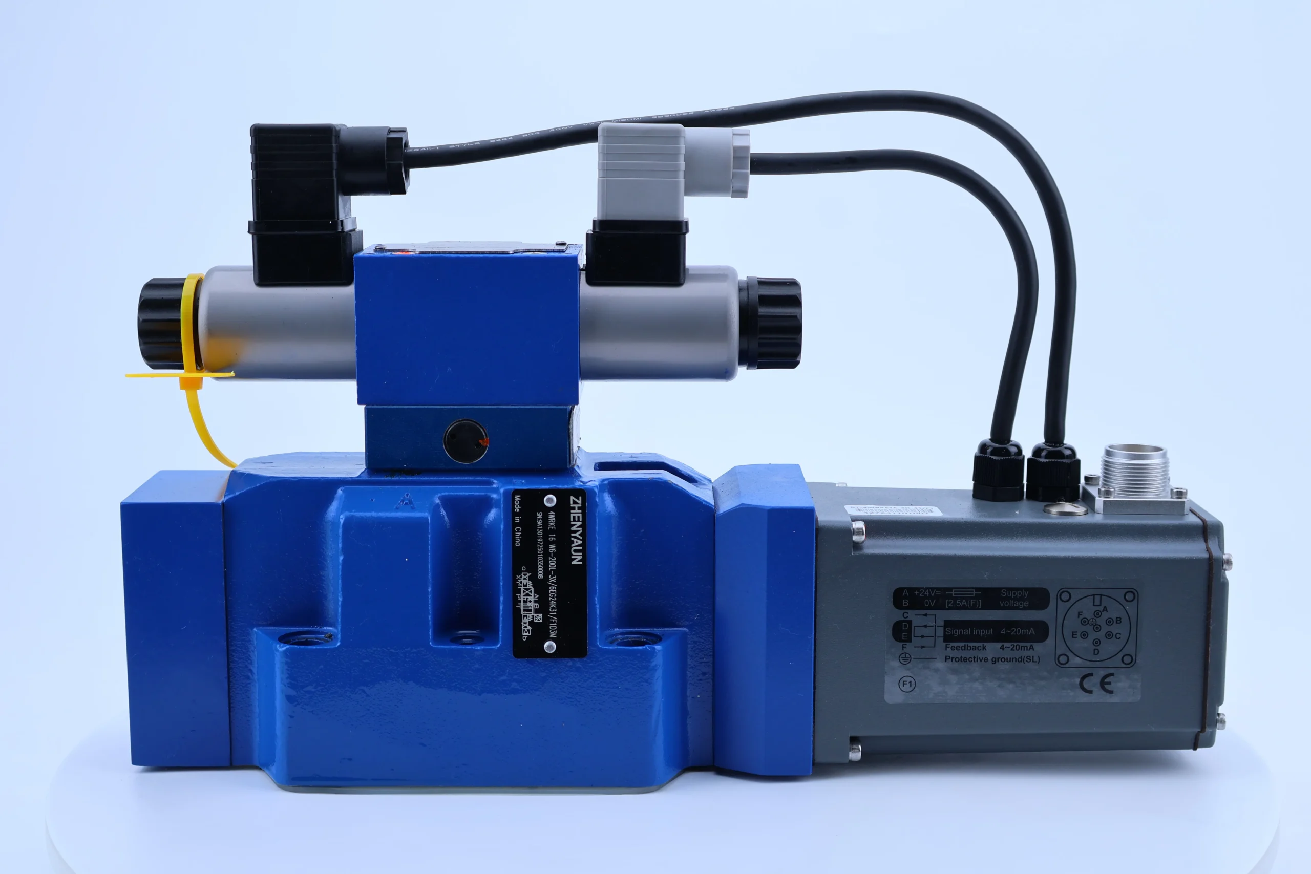


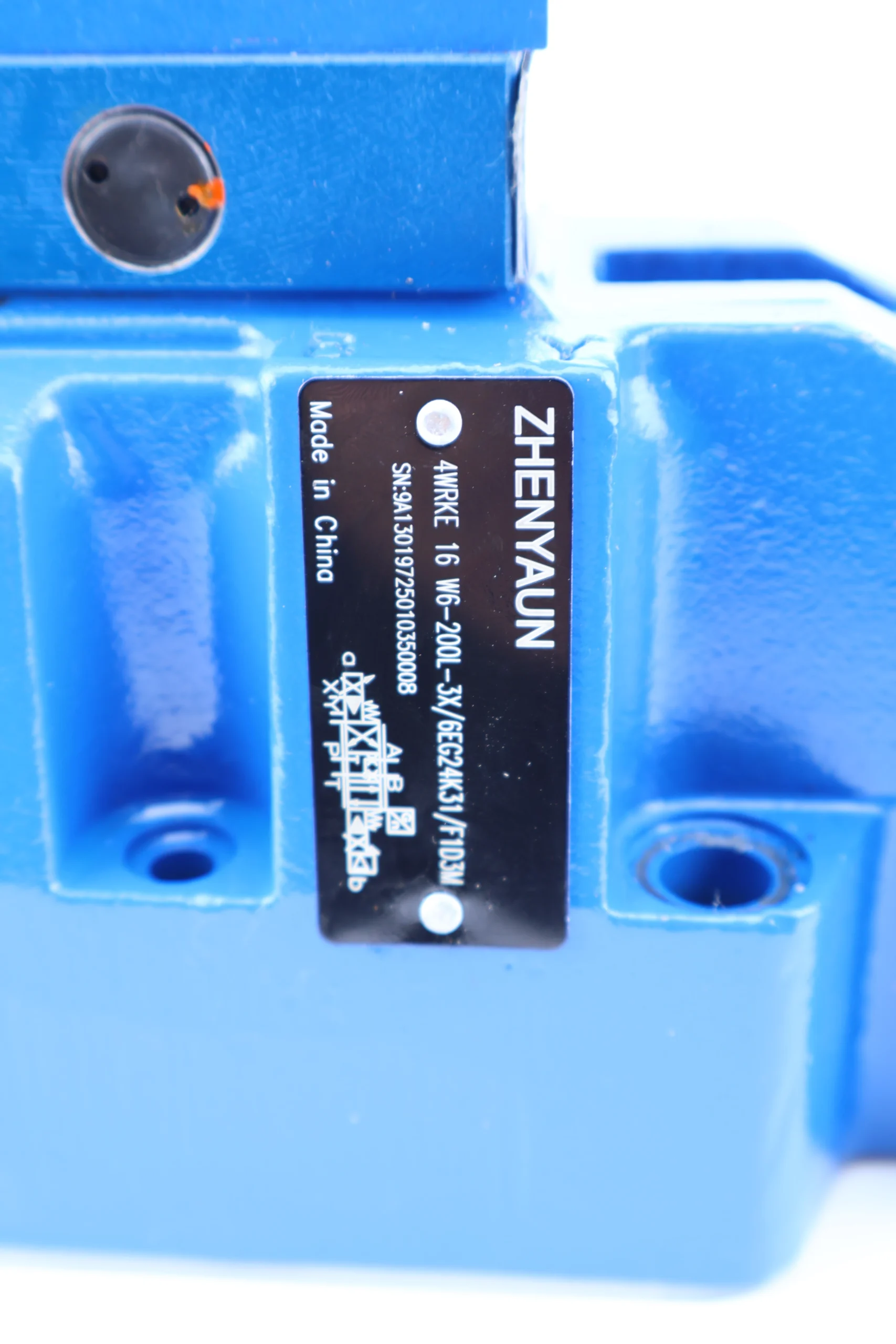

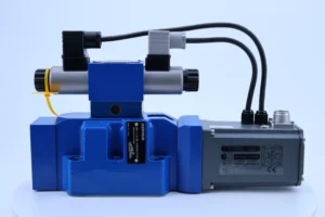
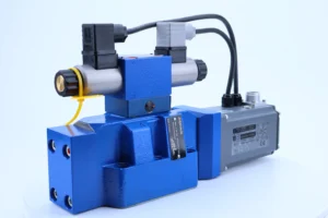

4WRKE16W6-200L-3X/6EG24K31/F1D3M Hydraulic Proportional Valve 4WRKE 4WRTE 10 16 25 27 32 Proportional Directional Control Valve
This model is a benchmark product for medium and high voltage electro-hydraulic proportional directional valves, with parameters that meet the strict requirements of precision hydraulic control systems. The specific indicators are as follows:
Pressure specification: Rated working pressure 31.5MPa, short-term maximum pressure up to 35MPa, meeting the high-pressure regulation requirements of heavy-duty equipment.
Flow performance: Nominal flow rate is 200L/min (” 200 “in the model indicates the core flow rate), and the flow stability deviation under rated pressure is ≤±2%.
Control accuracy: The repeat accuracy of valve core displacement is ≤±0.3%, and the position control accuracy can reach 0.1mm, making it suitable for high-precision positioning scenarios.
Response speed: Step response time ≤50ms (90% signal response), frequency response ≥10Hz, can quickly adapt to dynamic load changes.
Electrical parameters: It adopts a DC24V proportional electromagnet (marked with “24” in the model), with a control current range of 400-800mA, and is compatible with 4-20mA/0-10V standard signals.
Medium and environment: Compatible with ISO VG 32/46/68 anti-wear hydraulic oil, working temperature -20 ℃ to 70℃, anti-pollution grade up to ISO 4406 20/18/15.
Installation standard: The installation surface complies with ISO 4401-03 standard (marked with “3X”), adopts SAE flange connection, and is compatible with industrial general installation layout.2. Working Principle
This valve adopts a pilot-operated electro-hydraulic proportional control structure, achieving precise regulation through a three-level conversion of “electrical signal – hydraulic signal – mechanical action”. The specific process is as follows:
Signal input and amplification: The analog electrical signal (such as 4-20mA) output by the external controller enters the proportional electromagnet. The electromagnet converts the current signal into proportional electromagnetic force, driving the pilot valve core to move.
Pilot pressure regulation: The displacement of the pilot valve core changes the flow area of the control oil, generating a pilot pressure (0.4-2.5MPa) proportional to the electrical signal. This pressure is applied to the end of the main valve core through the internal oil passage.
Main valve flow distribution: Under the drive of the pilot pressure, the main valve core undergoes A linear displacement. The V-shaped control groove on its surface gradually opens, enabling the oil flow from port P to port A/B and from Port B/A to port T. The flow rate is directly proportional to the displacement of the valve core.
Closed-loop feedback correction: The built-in displacement sensor (marked with “F1”) monitors the position of the valve core in real time, feeds the signal back to the controller for comparison with the input signal, amplifies the deviation value and corrects the thrust of the electromagnet to ensure that the position of the valve core precisely matches the command.
Neutral reset mechanism: When the electromagnet is de-energized, the reset spring pushes the main valve core back to the neutral position, cutting off the connection between port P and port A/B, thus achieving the system’s pressure-holding or shutdown state.
3. Product features and advantages
Core features
Load sensitive compensation: Integrated pressure compensation valve (marked “K31”), which can sense changes in load pressure in real time, maintain stable flow by adjusting the opening degree of the main valve, and is not affected by load fluctuations.
Anti-pollution enhanced design: The valve core adopts hardening treatment (surface hardness HRC 58-62), combined with polytetrafluoroethylene combined seal, which can withstand ISO 4406 20/18/15 grade contaminated oil, reducing the risk of jamming.
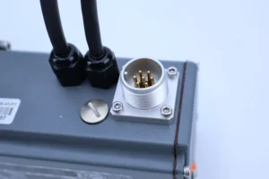
Modular integrated structure: The pilot stage, main valve stage and feedback module are independently packaged, supporting the replacement of vulnerable parts separately, and can expand the bus communication interface (such as PROFINET).
Safety redundancy design: Equipped with a manual emergency button, it can mechanically drive the main valve to act when the electromagnet fails. It also has overcurrent protection function to prevent electrical components from burning out.
Outstanding advantages
High control accuracy: Through closed-loop feedback control, the control deviations of flow and position are both 30% lower than the industry average, and 0.1mm-level positioning can be achieved in hydraulic cylinder drive scenarios.
Remarkable energy-saving effect: Compared with traditional on-off valves, by distributing flow on demand to reduce overflow loss, the system energy consumption can be reduced by 15% to 20%, which is in line with the requirements of green manufacturing.
Strong operational stability: It can operate continuously for 1,000 hours without failure at a rated pressure of 31.5MPa, and the service life of the sealing system reaches 12,000 hours, far exceeding the industry average of 8,000 hours.
Low maintenance cost: The modular design reduces the replacement time of vulnerable parts such as electromagnets and seals to within 2 hours, eliminating the need to disassemble the entire hydraulic circuit.
4. Usage functions and purposes
Core usage functions
Direction and flow coordinated control: By adjusting the displacement of the valve core, it simultaneously realizes the switching of the oil flow direction and flow distribution, driving the oil cylinder and hydraulic motor to complete actions such as extension, contraction and rotation.
Dynamic load adaptation: The pressure compensation function ensures a stable flow rate when the load changes (such as when an excavator is digging materials of different hardness), avoiding action lag or impact.
Precise speed control: In conjunction with the analog signals output by the PLC, it enables stepless speed regulation of the actuating elements, such as the segmented precise control of the injection speed of injection molding machines.
System status monitoring: Some models can provide feedback on valve core position, working pressure and other data through the bus interface, supporting predictive maintenance.
Main uses
As the “nerve center” of the hydraulic system, it achieves precise control over the actuating elements, overcomes the limitations of the traditional “start-stop” regulation of on-off valves, and is widely used in industrial and construction machinery scenarios that require continuous speed change and high-precision positioning.
5. Applicable machines and scenarios
Applicable machines
Construction machinery: The boom and bucket rod drive circuits of hydraulic excavators, and the luffing and slewing mechanisms of crawler cranes, ensure smooth operation under heavy loads.
Industrial machinery: The clamping and injection systems of injection molding machines, the clamping and ejection mechanisms of die-casting machines, and the pressure and speed coordination requirements that adapt to the molding process.
Machine tool equipment: The worktable feed system of large CNC floor boring and milling machines, and the slider motion control of presses, meeting the positioning accuracy requirements of 0.1mm grade.
Energy equipment: Yaw and pitch hydraulic systems for wind power equipment, roll gap adjustment mechanisms for metallurgical rolling mills, suitable for high reliability and long-term operation requirements.
Applicable scenarios
In the field of precision manufacturing: automotive parts stamping production lines, through segmented speed regulation, the stamping process can switch between “fast advance – working advance – fast retreat”, thereby enhancing the forming accuracy.
Heavy-duty operation scenarios: Hydraulic rock drills for mines can steplessly adjust the impact frequency and propulsion speed according to the hardness of the rock strata, reducing equipment wear and tear.
Automated production line: The hydraulic push mechanism of the intelligent logistics sorting equipment, in conjunction with the PLC, achieves synchronous actions at multiple stations, meeting the demands of flexible production.
Outdoor harsh environment: The lifting system of port cranes can still maintain stable control performance in environments with dust and large temperature differences.
6. Relevant models
Model of the same series and the same diameter
4WRKE16W6-100L-3X/6EG24K31/F1D3M (100L/min, suitable for low flow rates)
4WRKE16W6-150L-3X/6EG24K31/F1D3M (150L/min, medium flow compatible)
4WRKE16W6-250L-3X/6EG24K31/F1D3M (250L/min, suitable for large flow rates)
Derivative models with different diameters
4WRKE10W6-100L-3X/6EG24K31/F1D3M (10 bore, suitable for small devices)
4WRKE25W6-350L-3X/6EG24K31/F1D3M (25 bore, suitable for heavy-duty equipment)
4WRKE32W6-500L-3X/6EG24K31/F1D3M (32 bore, suitable for ultra-high flow rate)
Special function model
4WRKE16W6-200L-3X/6EG24K31/A1D3M (with fault alarm output function)
4WRKE16W6-200L-3X/6EG24K31/F1V (with manual flow regulation throttle port)
4WRKE16W6-200L-3X/6EG24K31/F1J (Supports PROFINET bus communication)


