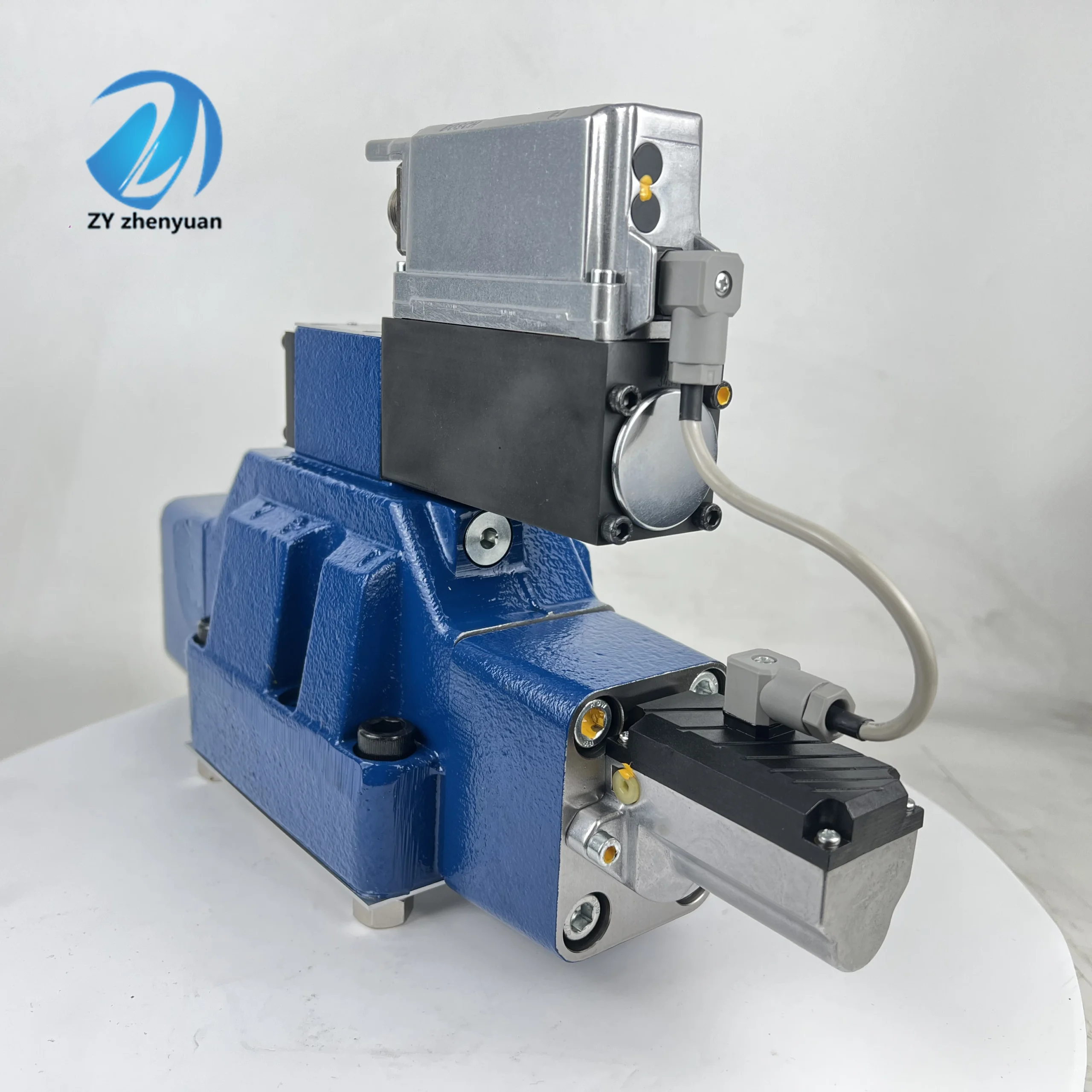
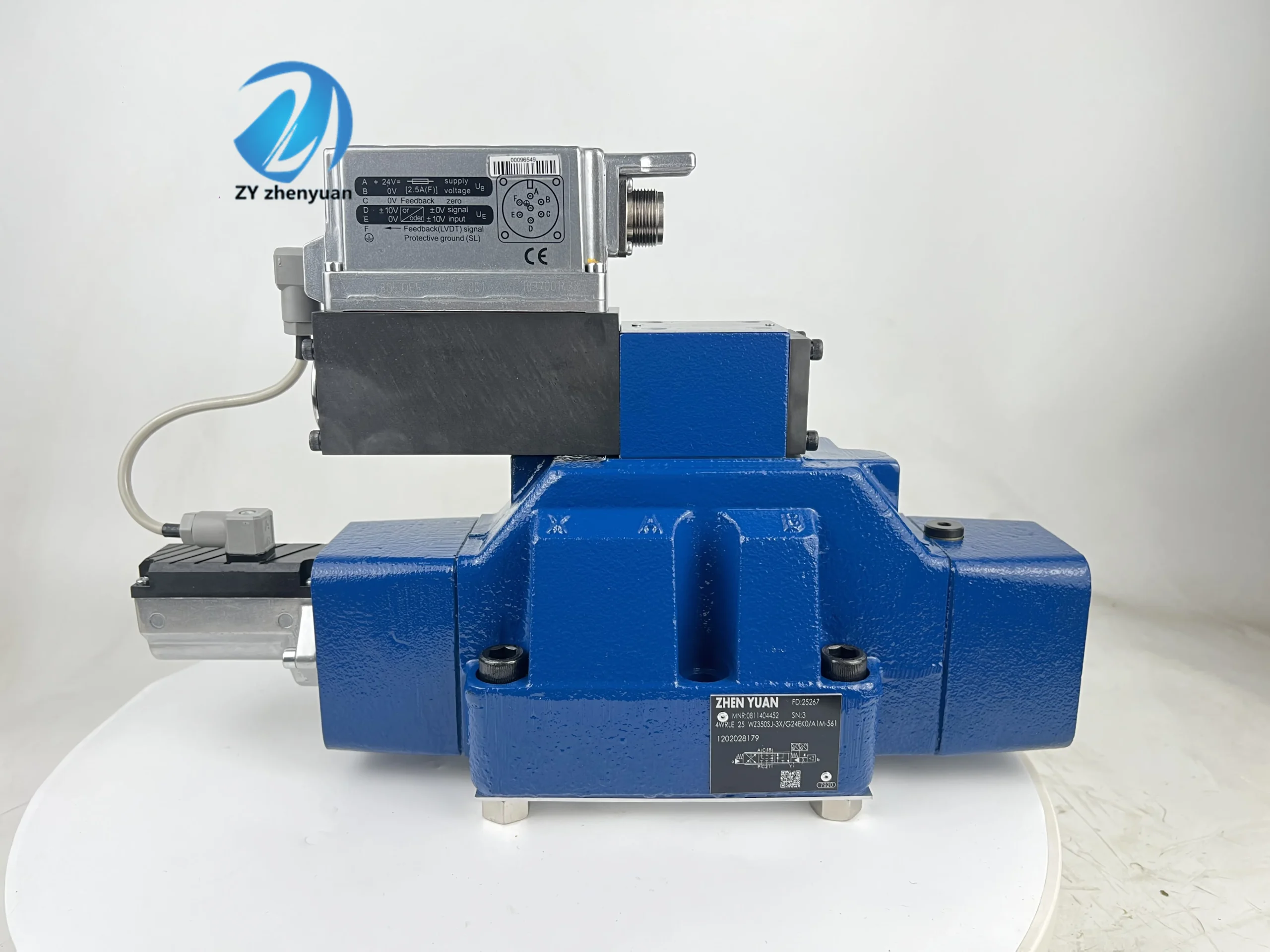
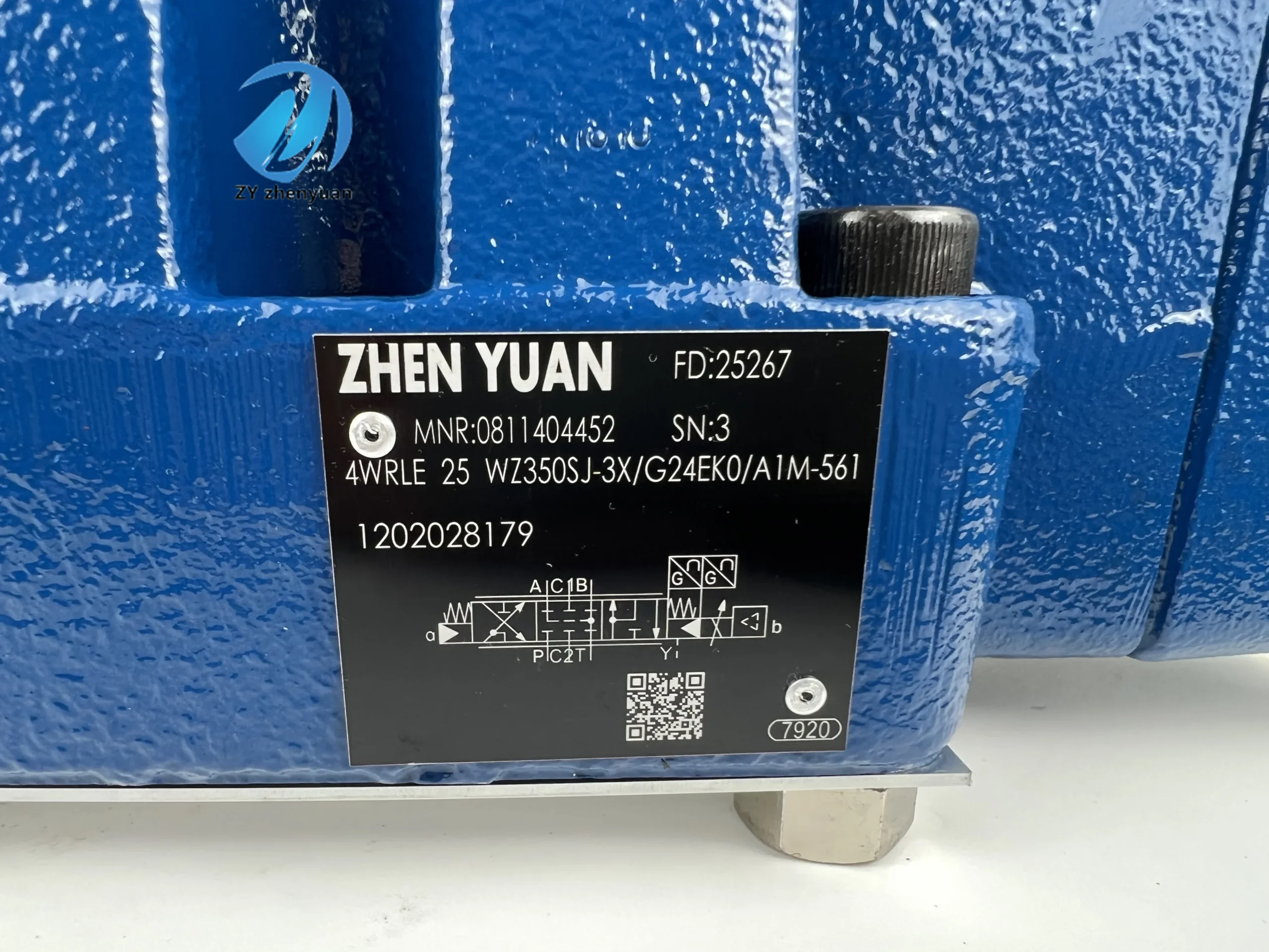

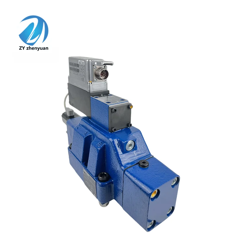
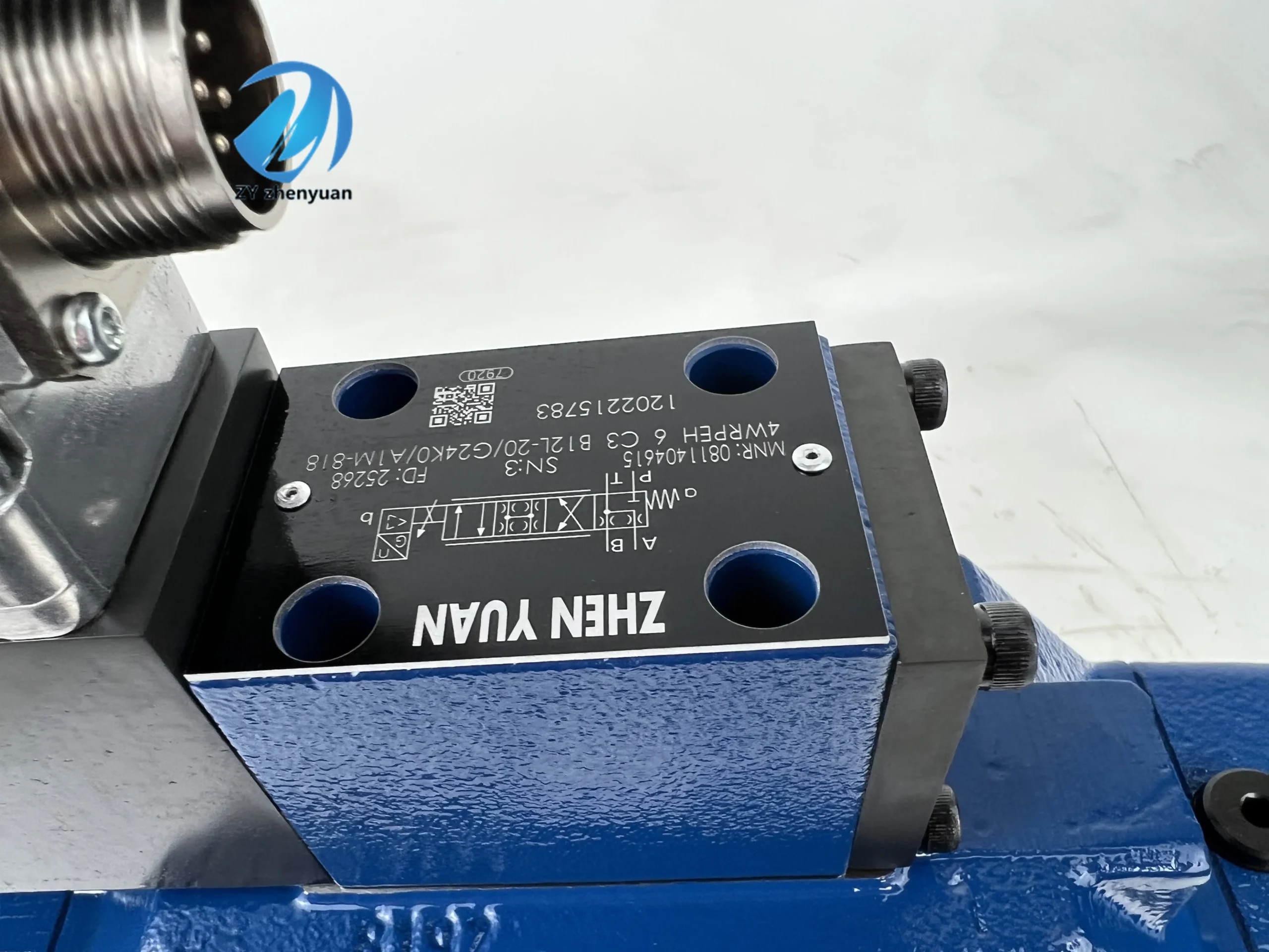


4WRPE 4WRKE 4WRSE 4WRZE 4WRPEH Series 4WRPH 10 C4 B100L-20/G24Z4/M Hydraulic Proportional Directional Valve
Core performance parameters
– Valve type: Direct-acting electro-hydraulic proportional directional control valve, servo-level control accuracy, with electronic position feedback function, in the 4/4 safe position when failure occurs; It is suitable for medium and high voltage high response ratio control scenarios, supports open-loop/closed-loop control, and can achieve precise and coordinated regulation of flow and direction.
– Pressure and flow rate: Rated working pressure 31.5 MPa, peak pressure 35 MPa (sustained for ≤3 seconds); Rated flow rate: 100 L/min (under conditions of 31.5 MPa and valve pressure drop of 1 MPa), flow regulation range: 10-100 L/min (corresponding to control signal: 4-20mA). Back pressure tolerance ≤8 MPa.
– Control performance: Compatible with DC4-20mA current signals or ±10V voltage signals, signal resolution ≤0.05mA; Flow control accuracy: ±0.5% (at rated flow), position repeatability accuracy: ±0.01mm; The response time is ≤20ms (when the flow rate increases from 10% to 90%), and the hysteresis is ≤1%.
– Power and efficiency: The rated voltage of the proportional electromagnet is DC24V, and the rated power is 20W. The total efficiency of the valve group is ≥92% (under rated working conditions), and the internal leakage is ≤0.2 mL/min (at 31.5 MPa).
2. Structure and connection parameters
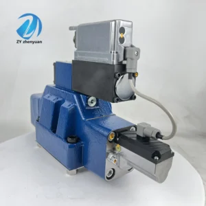
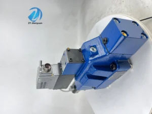
– Structural type: Direct-acting valve core structure + integrated electronic feedback module, including main valve core, proportional electromagnet, displacement sensor, and built-in electronic amplifier; Supports horizontal installation, the installation surface is compatible with the ISO 6264 standard, and features a single-ended driver design.
– Core material: The main valve body is made of 42CrMo forged steel (quenched and tempered, hardness HB220-250); The valve core is made of stainless steel 17-4PH (surface nitrided treatment, hardness HV800-1000). The sealing parts are made of high-pressure resistant perfluoroether rubber (with a temperature resistance range of -20℃ to 120℃). The core of the electromagnet is DT4C high-permeability pure iron.
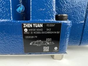
– Connection specifications: The diameters of the oil inlet (P port), return oil port (T port), and working port (A/B port) are all Φ10mm, and the interface thread is M27×1.5. The control signal interface is an M16 aviation plug (with shielding). The total weight of the valve assembly is approximately 10 kg, and its external dimensions (length × width × height) ≈220×140×160mm.
3. Medium and Environmental requirements
– Medium requirements: It is recommended to use L-HM 46/68 anti-wear hydraulic oil. For low-temperature environments (below -30℃), L-HV 46 anti-wear hydraulic oil is selected. The kinematic viscosity of the oil is 10-400 mm²/s, the moisture content is ≤0.03%, and the acid value is ≤0.5 mgKOH/g.
– Cleanliness standard: The oil cleanliness must reach ISO 4406 15/12 grade. The system must be equipped with a 3-5 μm fine filter, and a 100 μm coarse filter must be placed in front of the oil suction port. The pressure difference alarm threshold of the fine filter is set at 0.3 MPa.
– Environmental parameters: Operating environment temperature -20℃ to 80℃, relative humidity ≤95% (short-term condensation is allowed); With protection grades of IP65 (valve body) and IP67 (control plug), it is suitable for medium pollution working conditions in industrial production lines, construction machinery, etc.Ii. Working Principle
This proportional valve is a direct-acting servo-level proportional directional control valve. Its core achieves high-response control through precise proportional conversion of “electrical signal – mechanical displacement – hydraulic parameters” and a closed-loop feedback mechanism. The specific process is as follows:
1. Basic control process
The controller outputs a 4-20mA proportional signal to the built-in electronic amplifier. The amplifier amplifies the signal and drives the proportional electromagnet, which generates an electromagnetic force proportional to the signal strength, directly pushing the main valve core to move along the axis (without the need for a pilot stage transition). The movement of the valve core is collected in real time by the integrated displacement sensor and fed back to the amplifier to form a closed-loop control, ensuring that the position of the valve core precisely matches the input signal. By changing the flow area between the valve core and the valve sleeve and the direction of oil flow, synchronous proportional control of the flow rate (10-100 L/min) and the direction of the oil circuit can be achieved.
2. Safety and compensation mechanism
– Failure safety: When the control signal is interrupted or the system loses power, the valve core automatically returns to the 4/4 middle position (closing ports P, A, and B, and allowing flow to pass through port T) under the action of the reset spring, cutting off the working oil circuit to prevent unexpected load actions and enhance system safety.
– Anti-interference compensation: Built-in pressure compensation valve. When the system pressure fluctuates within ±2 MPa, it automatically adjusts the opening degree of the valve core throttle port to maintain a stable flow rate (fluctuation ≤0.5%). The electronic amplifier is designed to resist electromagnetic interference and can withstand the interference of high-frequency electromagnetic radiation on the control signal.
Iii. Product Features and Advantages
– Servo-level control accuracy: The direct-acting structure eliminates the error of the pilot stage, with a flow control accuracy of ±0.5% and a position repeatability accuracy of ±0.01mm, which is 60% higher than the accuracy of ordinary pilot-operated proportional valves. The 20ms rapid response enables high-frequency adjustment (≤50 times per minute), making it suitable for precision forming and dynamic load control scenarios.
– High reliability and safety: Fail-safe median design + closed-loop position feedback to prevent equipment loss of control caused by signal interruption; The 17-4PH valve core has excellent wear resistance. Under rated working conditions, its trouble-free operation life reaches 20,000 hours, which is 30% longer than that of ordinary proportional valves.
– Strong integration and adaptability: Equipped with built-in electronic amplifiers, displacement sensors and pressure compensation valves, no additional control modules are required, reducing system integration costs by 40%. Compatible with 4-20mA/±10V dual signals, it can be directly connected to mainstream controllers such as PLCS and numerical control systems, and is suitable for upgrading new and old equipment.
– Energy conservation and low loss: The direct-acting structure reduces pressure loss, and the valve group efficiency reaches 92%, saving 15-20% energy compared to pilot-operated proportional valves. The internal leakage is ≤0.2 mL/min, which reduces the heat generation of the oil. The system oil temperature can be lowered by 8-12℃, and the service life of the oil can be prolonged.
– Wide working condition adaptability: 31.5MPa high-pressure compatibility +IP67 protection, capable of stable operation in complex environments such as bumpy construction machinery and industrial workshop dust. Designed with a wide temperature range of -20℃ to 80℃, it is suitable for construction in cold regions and high-temperature production scenarios.
Iv. Usage Functions and Purposes
1. Core usage functions
– Precise flow regulation: By linearly controlling the flow rate from 10 to 100 L/min through proportional signals, the load speed can be precisely adjusted steplessly (such as the speed regulation of machine tool spindles and the gradual change of injection speed in injection molding machines), with a regulation resolution of up to 0.1 L/min.
– High-frequency reversing control: 20ms rapid response + precise position control, achieving high-frequency and smooth switching of the oil circuit direction (such as hydraulic robot joint drive), with no pressure shock during the switching process (shock pressure ≤1 MPa).
– Closed-loop dynamic compensation: Dual closed-loop of pressure compensation and position feedback. When the load or system pressure fluctuates, the flow correction is completed within 5ms to maintain the stability of control parameters (such as precise control of the pressing force of the press).
– Status monitoring and Diagnosis: The built-in electronic amplifier can output status signals such as the valve core position and working current, supporting real-time monitoring by the controller. It is equipped with overcurrent and over-temperature fault diagnosis functions, and automatically switches to safe mode when a fault occurs.
2. Main application fields
– Industrial manufacturing field: Spindle drive for large CNC lathes, injection/holding pressure control for 1000-2000 ton injection molding machines, and pressing control for high-precision hydraulic presses, suitable for precision forming and processing scenarios.
In the field of construction machinery: 20-30 ton excavator bucket/boom compound action control, large loader lifting/steering coordinated control, crawler crane luffing mechanism speed regulation, suitable for complex dynamic load scenarios.
– Testing and special fields: Dynamic loading control of hydraulic component test benches, speed regulation of ship propulsion systems, precise drive of aerospace component test benches, suitable for high-demand testing and special power control scenarios.
V. Applicable Machines and Scenarios
1. Adapt to the core machine
– Industrial equipment: CNC lathes with a diameter of over 500mm, injection molding machines with a capacity of 1000-2000 tons, precision hydraulic presses with a capacity of 800-1500 tons, and hydraulic servo robots.
– Construction machinery: 20-30 ton crawler excavators, 5-8 ton wheel loaders, 25-50 ton truck cranes.
– Test equipment: Hydraulic valve test bench, simulation test bench for hydraulic systems of construction machinery, hydraulic loading test bench for aviation components.
2. Typical application scenarios
– Excavator compound action scene: As a proportional valve for the coordinated control of the 25-ton excavator boom and bucket arm, it receives a 4-20mA signal from the controller and synchronously adjusts the two flow rates (30-80 L/min for the boom and 20-60 L/min for the bucket arm), achieving precise loading and rotation compound actions. The flow rate correction response when the load fluctuates is ≤5ms, making it suitable for mining operations.
– Precision control scenarios for injection molding machines: It is equipped with a 150-ton injection molding machine injection system. During the injection stage, a 20mA signal is output with a flow rate of 100 L/min to achieve rapid advancement (1.2m /s speed). During the pressure-holding stage, the pressure is reduced to a 5mA signal corresponding to a stable flow rate of 10 L/min. The dimensional error of large automotive bumpers is ≤0.2%, making it suitable for batch precision injection molding scenarios.
Dynamic loading scenario of the test bench: It is used for loading control of the hydraulic motor test bench. By linearly adjusting the loading pressure (0-31.5MPa) and flow rate (10-100L /min) through a 4-20mA signal, it simulates the load under different working conditions of the motor. The repeatability error of the test data is ≤0.5%, making it suitable for the factory inspection scenario of hydraulic components.
Six. Similar models
1. Alternative models of the same series
-4WRPH 8 C4 B60L-20/G24Z4/M: A small-bore model of the same structure, with a bore diameter of Φ8mm, a rated flow rate of 60L /min, consistent pressure parameters, compatible installation dimensions, suitable for small precision hydraulic systems (such as CNC milling machines), and a cost 30% lower than the original model.
-4WRPH 12 C4 B150L-20/G24Z4/M: Large-diameter model of the same series, with a diameter of Φ12mm, a rated flow rate of 150L /min, and the same pressure parameters. It is suitable for excavators over 30 tons and injection molding machines over 2,000 tons. The cost is 40% higher than that of the original model.
2. Cross-series alternative models
-4WRPH 10 C4 B100L-20/G12Z4/M: Low-voltage model, proportional electromagnet rated voltage DC12V, flow and pressure parameters are the same as the original model, suitable for 12V power supply systems in vehicles (such as small construction machinery), with the same cost.
-4WRPH 10 C4 B100L-20/G24Z4/B: An upgraded bus control model that supports CANopen/EtherCAT bus communication, replacing traditional analog signals. It is suitable for centralized control scenarios of multiple valve groups (such as automated production lines), and its cost is 50% higher than that of the original model.
-4WRPH 10 C4 B100L-20/G24Z4/H: High-temperature upgraded model, with the temperature resistance of the sealing parts increased to 150℃. The valve core is coated with ceramic, suitable for high-temperature working conditions in metallurgy, coking and other industries (oil temperature ≤130℃). The cost is 35% higher than that of the original model.
Vii. Precautions for Use
1. Oil management
– L-HM 46/68 anti-wear hydraulic oil must be selected. It is strictly prohibited to mix different grades or deteriorated oils. After the new valve has been in operation for 300 hours for the first time, it is mandatory to change the oil. Subsequently, the oil should be changed every 1000 hours. Before changing the oil, the oil tank, pipelines and filters should be flushed with the same grade of oil to ensure that the residual impurity is ≤5mg/L.
– Check the oil level daily (not less than 2/3 of the oil tank capacity), test the pressure difference of the fine filter weekly (replace it immediately if > 0.3 MPa), and take samples monthly to test the cleanliness of the oil (to meet ISO 4406 15/12 grade), moisture (≤0.03%) and viscosity; When emulsification, discoloration or presence of metal debris in the oil is detected, the system should be thoroughly disassembled and cleaned, and the oil replaced.
2. Installation and commissioning
The installation location should be far away from vibration sources such as pumps and motors (vibration acceleration ≤5 m/s²). If necessary, shock-absorbing brackets should be added. The connection between the pipeline and the valve body must be precisely aligned to avoid forced screwing which may cause deformation of the valve body. Apply hydraulic special sealant at the threaded connection (do not use PTFE tape).
Before debugging, disconnect the control signal and circulate low-pressure oil (2-3 MPa) to flush the inner cavity of the valve body for 30 minutes. After the signal is connected, apply the minimum signal of 4mA first and slowly increase it to the maximum signal of 20mA to calibrate the flow linearity (deviation ≤0.5%). When debugging under load, gradually increase the pressure to the rated value and confirm the response time and compensation performance.
Electrical connections must use shielded wires, with the shielding layer grounded at one end (grounding resistance ≤1Ω), and the distance from the power cable should be no less than 50cm. Aviation plugs should be coated with waterproof grease and tightened to prevent dust and oil from entering and causing signal distortion.
3. Operation and Maintenance
During operation, real-time monitoring of the valve group temperature (normal ≤60℃, maximum ≤80℃), inlet and outlet pressures, and control signals is carried out. If there is a sudden temperature rise of more than 10℃, a pressure fluctuation of more than 1 MPa, or a flow deviation of more than 1%, immediately stop the machine to check for oil contamination, valve core jamming or electromagnet failure.
– Regular maintenance every 2000 hours: Replace the seals and fine filter elements; Check the fit clearance between the valve core and the valve sleeve (replace if it is greater than 0.03mm). Calibrate the displacement sensor and electronic amplifier to ensure control accuracy; Clean the aviation plugs and check the tightness of the terminal blocks.
It is prohibited to disassemble the valve assembly when the system is under pressure. When the valve core is stuck, do not pry it with hard objects. Instead, reverse flush it with low-pressure oil or have it disassembled by professionals. Before a long-term shutdown (> 7 days), reset the valve core to the neutral position and fill the cylinder with oil to prevent rust.
4. Storage protection
When stored for a long time, use a special plug to seal the oil port, fill the valve body with anti-rust oil (fill the interior), and put a dust and waterproof cap on the control plug. Store in a dry and well-ventilated warehouse (0-40℃, humidity ≤60%), avoid direct sunlight and heavy object compression. Check the condition of the anti-rust oil monthly.
Before being put into use after being idle for more than 6 months, thoroughly clean the inner cavity of the valve body and replace the sealing parts. Test the flexibility of the valve core with low-pressure oil, connect the signal to calibrate the flow and position parameters, and run continuously for one hour without any abnormalities before connecting to the system.


