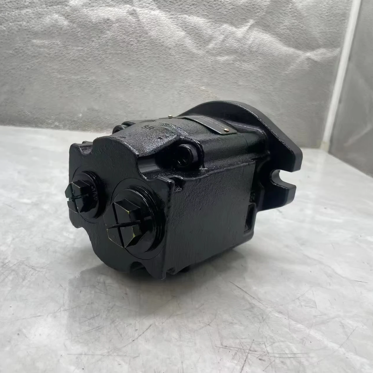
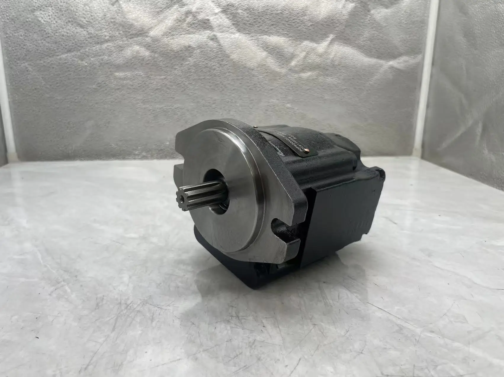
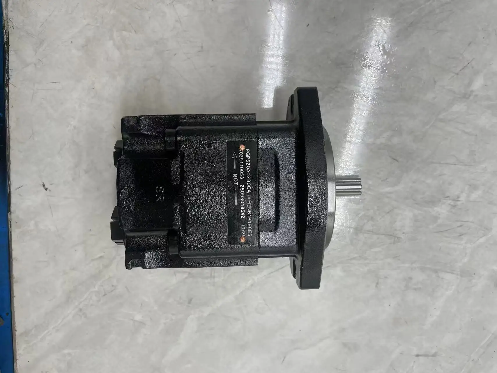
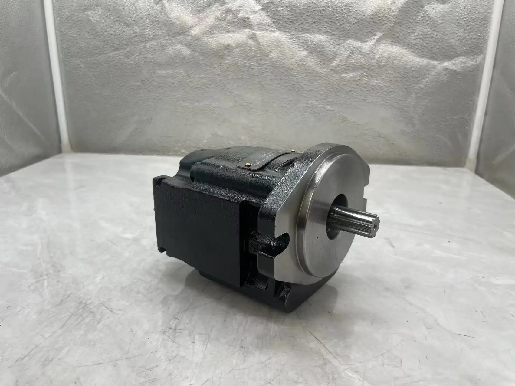
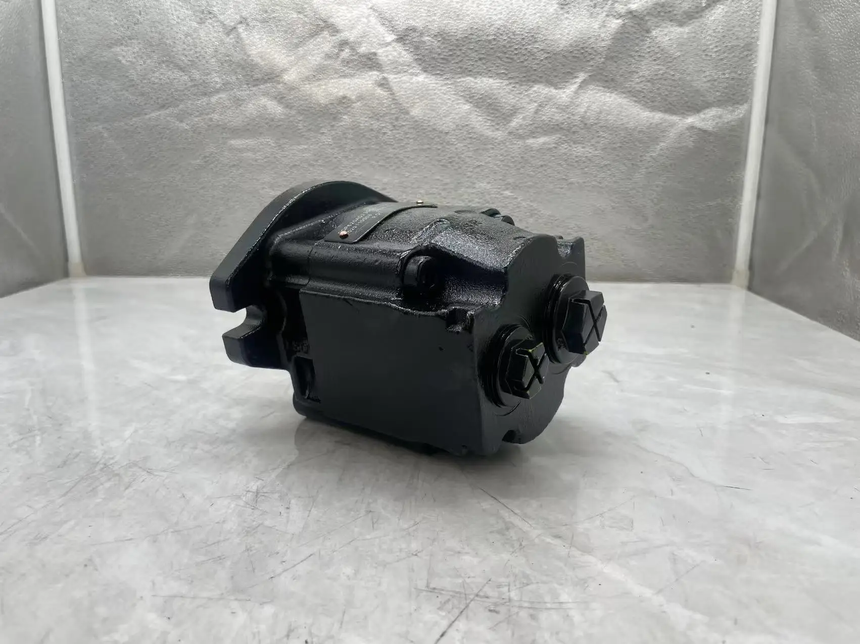


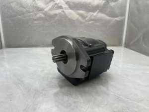
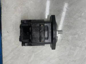


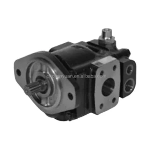
7029110058 Hydraulic Gear Pump 7029120005 7029120058 PGP505 PGP530 Excavator Hydraulic Gear Pump for Backhoe Loader
Core performance parameters- Pump type: External meshing gear fixed displacement pump, single-stage medium and high-pressure design, unidirectional oil suction and discharge, suitable for medium and large hydraulic systems, providing a stable flow power source for multiple actuators.
– Displacement and pressure parameters: Rated displacement 100 mL/r; Rated working pressure: 16 MPa, maximum allowable pressure: 18 MPa (short-term ≤10 seconds); The rated speed is 1500 r/min, the maximum speed is 1800 r/min (short-term ≤5 minutes), and the minimum stable speed is 400 r/min.
– Efficiency and flow parameters: Rated working condition volumetric efficiency ≥88%, total efficiency ≥82%; The output flow rate at the rated speed is 150 L/min (calculated by multiplying the displacement by the speed). The driving power is approximately 40 kW (under rated working conditions).
– Operating characteristics: Continuous operating oil temperature ≤85℃, rated working condition noise value ≤90 dB (measured at 1 meter); The fault-free operating life under rated conditions is ≥ 8,000 hours.
2. Structure and connection parameters
– Structural type: External meshing involute gear structure, integrating ductile iron pump body, alloy gear pair, floating shaft sleeve, pressure compensation plate and skeleton oil seal; The floating bushing is adopted to automatically compensate for the wear clearance. The built-in pressure relief valve prevents overpressure, and the pump body is equipped with reinforcing ribs to resist impact.
– Core material: The driving/driven gears are made of chromium-nickel alloy steel (surface carburized and quenched, hardness HRC60-64); The bushing is made of tin bronze ZCuSn6Zn6Pb3 (precision ground). The pump body is made of ductile iron QT500-7 (tensile strength ≥500MPa). The sealing part is a combination of high-pressure resistant nitrile rubber and polytetrafluoroethylene (with a temperature resistance of ≤100℃).
– Connection specifications: Oil port flange connection (suction port S is DN50, outlet port P is DN40); The installation method is foot mounting (compatible with GB/T 5801 standard foot mounting). The input shaft is connected by a flat key (specification: 20×60). The overall weight is approximately 45 kg, and the external dimensions (length × width × height) ≈520×350×300 mm.
3. Medium and Environmental requirements
– Medium requirements: L-HM 46 anti-wear hydraulic oil is suitable for normal temperature. L-HM 32 is selected for low-temperature environment (below -20℃). The allowable medium viscosity is 10-400 mm²/s, the moisture content is ≤0.03%, and the solid particle size is ≤20 μm (the anti-pollution ability is superior to that of the plunger pump).
– Environmental parameters: The oil cleanliness should reach ISO 4406 16/13 grade, and a 20 μm filter should be placed in front of the oil suction port. The operating environment temperature ranges from -30℃ to 90℃, with a relative humidity of no more than 95%. The protection grade is IP65. It is suitable for scenarios such as construction machinery, industrial hydraulic stations, and mining equipment.
Ii. Working Principle
This pump is an external meshing gear quantitative pump. Its core converts mechanical energy into hydraulic energy through a mechanism of “motor-driven gear rotation – changing the volume between teeth for oil suction and discharge – clearance compensation for pressure stabilization”. The specific process is as follows:
1. The basic process of oil suction and discharge
The motor drives the driving gear to rotate through the flat key, and the meshing of the driving gear drives the driven gear to rotate in the opposite direction. When the meshing teeth of the two gears gradually separate in the oil suction area (on the left side of the pump body), a vacuum chamber is formed between the teeth, and the hydraulic oil is sucked into the teeth through the oil suction port S under the action of atmospheric pressure. As the gears rotate, the teeth carrying the oil move to the oil pressure area (on the right side of the pump body). The meshing teeth gradually mesh, reducing the volume between the teeth. The oil is squeezed into high-pressure oil and discharged into the system through the oil outlet P, completing the oil suction and discharge cycle.
2. Gap compensation and voltage stabilization process
The pump is equipped with an internal floating shaft sleeve and pressure compensation plate structure: High-pressure oil enters the rear end of the floating shaft sleeve, pushing the shaft sleeve to closely adhere to the gear end face, automatically compensating for the wear gap between the gear and the shaft sleeve, and maintaining the long-term stability of volumetric efficiency. When the system pressure exceeds 18 MPa, the built-in pressure relief valve opens to release some high-pressure oil back into the suction chamber, preventing the gears and pump body from being damaged due to overpressure and ensuring the stability of the output pressure.
3. Lubrication and heat dissipation mechanism
During the gear meshing process, the oil also plays a lubricating role, reducing the wear of the gear tooth surface and the shaft sleeve. The pump body is integrated with a heat dissipation oil circuit, which is connected to the system return oil to carry away the heat generated by the rotation and friction of the gears. Combined with the heat dissipation characteristics of the ductile iron pump body, it maintains the oil temperature within a safe range.
Iii. Product Features and Advantages
– Large flow stable supply: Designed with a displacement of 100 mL/r and a rated flow rate of up to 150 L/min, it can simultaneously drive 2-3 medium and large actuators (such as loading boom + steering coordination). The quantitative output feature is suitable for multi-action synchronous control scenarios. The flow fluctuation is ≤3%, and the flow stability is improved by 15% compared with the plunger pump of the same displacement.
– Strong anti-pollution ability: The external meshing structure has no precision plunger pair, allowing the oil to contain particles smaller than 20 μm, and the anti-pollution grade is one level higher than that of plunger pumps. The wear-resistant combination of chromium-nickel alloy steel gears and tin bronze bushings can maintain a long service life even in conditions with trace impurities, making it suitable for dusty environments such as mines and construction machinery.
– Robust structure and long service life: The ductile iron pump body is equipped with reinforcing ribs, capable of withstanding an impact pressure of up to 25 MPa, making it suitable for the frequent start-stop impact loads of construction machinery. The floating bushing clearance compensation design keeps the volumetric efficiency stable at over 88% for a long time, and the fault-free life under rated working conditions is ≥ 8,000 hours, which is 30% longer than that of ordinary gear pumps.
– Easy installation and maintenance: Standardized feet and flange connection, which can directly replace products of the same specification but different brands. The key components (gears, shaft sleeves) are modularly designed. During fault maintenance, there is no need for overall disassembly, and the maintenance time is reduced by 60% compared with the plunger pump. The built-in pressure relief valve eliminates the need for an additional system relief valve, simplifying integration costs.
Iv. Usage Functions and Purposes
1. Core usage functions
– Medium and high-pressure quantitative oil supply: It provides a stable and quantitative oil source for medium and high-pressure systems, replacing the “parallel operation of multiple small-displacement pumps” solution, simplifying the system structure, and adapting to scenarios where multiple actuators operate synchronously (such as the coordinated operation of the loader bucket and boom).
– Anti-pollution power output: It can still operate stably in conditions with low oil cleanliness (such as mines and construction sites), without the need for frequent filter replacement, reducing operation and maintenance costs. The built-in pressure relief valve provides overpressure protection for the system, eliminating the need for additional safety valves.
– Long-term continuous operation: The heat dissipation oil circuit and wear-resistant structure design support 24-hour continuous operation, suitable for continuous production scenarios such as industrial hydraulic stations and large mixing plants. The operational stability is 25% higher than that of ordinary gear pumps.
2. Main application fields
In the field of small and medium-sized construction machinery: hydraulic systems for 10-20 ton wheel loaders, luffing mechanisms for 10-15 ton crawler cranes, and walking drives for 15-ton and above bulldozers, suitable for outdoor heavy-load operations.
– Industrial hydraulics field: Hydraulic stations for medium-sized metallurgical equipment, hydraulic systems for concrete mixing plants (HZS120 and above), drive circuits for heavy-duty conveying equipment, suitable for continuous high-flow production scenarios.
– Mining and special fields: Hydraulic systems for small-scale mining loaders, drives for medium-sized port loading and unloading equipment, and hydraulic actuators for large agricultural machinery (such as combine harvesters), suitable for dusty and heavy-load scenarios.
V. Applicable Machines and Scenarios
1. Adapt to the core machine
– Construction machinery: 10-20 ton wheel loaders, 10-15 ton crawler cranes, 15-20 ton bulldozers.
– Industrial equipment: Metallurgical hydraulic stations over 300 tons, HZS120-HZS180 concrete mixing plants, heavy-duty belt conveyors (belt width ≥1.2 meters).
– Special equipment: Small-scale mine loaders, medium-sized container stackers for ports, large combine harvesters.
2. Typical application scenarios
– Loader operation scenario: As the main pump of a 15-ton wheel loader, when the input speed is 1500 r/min, the output flow is 150 L/min and the pressure is 16 MPa. It simultaneously drives the bucket lifting, boom flipping and walking mechanism, with smooth coordinated action response. IP65 protection is suitable for the dusty environment of construction sites. It can operate continuously for 12 hours a day without failure.
– Hydraulic system scenario of the mixing plant: It is matched with the HZS150 concrete mixing plant, providing oil for multiple actuating mechanisms such as the mixing host, discharge door, and conveyor belt. The output pressure is 14 MPa and the flow rate is 140 L/min. It supports 24-hour continuous mixing operation. The anti-pollution design extends the filter replacement cycle to 1500 hours, which is 50% longer than that of ordinary pumps.
– Mining scraper drive scenario: It drives the walking and bucket mechanisms of small mining scrapers, with an output pressure of 16 MPa and a flow rate of 130 L/min. It can still operate stably under the condition that the oil contains trace amounts of rock debris. The floating shaft sleeve compensation design maintains the volumetric efficiency above 86%, and it can work for an average of 28 days per month without failure or shutdown.
Six. Similar models
1. Alternative models of the same series
-7029110048: Small-displacement model of the same structure, with a rated displacement of 80 mL/r and a rated flow rate of 120 L/min. The pressure parameters are consistent. It is suitable for 10-15 ton loaders, HZS100 mixing plants and other equipment. The cost is 25% lower than the original model.
-7029110068: Large-displacement model of the same series, with a rated displacement of 125 mL/r and a rated flow rate of 187.5 L/min. The pressure parameters are the same. It is suitable for ultra-heavy-duty and high-flow equipment such as 20-25 ton loaders and HZS200 mixing plants. The cost is 35% higher than that of the original model.
2. Cross-series alternative models
-7029110058-H: High-pressure enhanced model, rated working pressure 20 MPa, consistent displacement and flow parameters, suitable for ultra-high pressure scenarios in mines (such as small tunnel boring machines), with a cost 25% higher than the original model.
-7029110058-F: Different installation form models (with feet changed to flange installation), suitable for equipment with limited space (such as auxiliary hydraulic stations for small shield machines), with the cost remaining the same.
-7029110058-D: Low-temperature compatible model. The sealing parts are made of low-temperature resistant fluororubber. The working temperature range is -40℃ to 90℃. It is suitable for construction machinery in extremely cold regions. The cost is 30% higher than that of the original model.
Vii. Precautions for Use
1. Medium and Selection management
– Strictly select L-HM 32/46 anti-wear hydraulic oil. It is strictly prohibited to mix oils of different grades or use inferior oils with corrosiveness and high moisture content. Select the type based on the system flow rate (≤150 L/min) and pressure (≤16 MPa). It is strictly prohibited to use the equipment beyond the specified parameters to avoid wear on the gear tooth surface.
Before the new system is used for the first time, the pipelines and pump chambers should be flushed with clean oil for more than 150 minutes to remove the remaining iron filings and welding slag from the installation. The diameter of the oil suction pipeline should be no less than 50mm and the length no more than 3 meters to avoid excessive oil suction resistance causing cavitation.
2. Installation and commissioning
When installing, confirm the direction of the oil port (S for oil suction and P for oil discharge). It is strictly forbidden to connect them in reverse to prevent damage to the pump body. The input shaft and the motor are connected by an elastic coupling, with a coaxiality error of no more than 0.15mm, to prevent abnormal gear meshing or shaft sleeve wear caused by eccentric loading.
Before debugging, manually turn the wheel 3 to 5 times to confirm there is no jamming or abnormal noise. When starting up for the first time, introduce low-pressure oil (5 MPa) and run it at low speed (600 r/min) without load for 30 minutes. Gradually increase it to the rated parameters and check the pressure stability and leakage rate (a leakage rate of ≤8 mL/min at the rated pressure is normal).
When installed outdoors or in mines, apply oil-resistant sealant to the connection points of the pump body feet and install dust covers. The pump body foundation needs to be reinforced and shock-absorbing pads installed to prevent pipeline loosening or increased impact from gear meshing caused by vibration.
3. Operation and Maintenance
During operation, the pump body temperature (normal ≤80℃, maximum ≤90℃), outlet pressure and noise should be monitored weekly. If the temperature rises sharply by more than 15℃, the pressure fluctuates by more than 1.5MPa, or the noise abnormally increases (> 98dB), stop the machine immediately for inspection, with a focus on checking the oil contamination level, gear wear or shaft sleeve clearance.
– Regular maintenance every 4,000 hours: Disassemble and clean the pump body, and check the wear of the gear tooth surface (replace when the tooth thickness wear is greater than 0.5mm). Replace the sealing parts, shaft sleeves and filters, reassemble and test the volumetric efficiency (≥85% is considered up to standard).
– It is strictly prohibited to run the gear without oil for more than 5 seconds (idling for more than 5 seconds may cause sintering of the gear tooth surface). It is strictly prohibited to operate for a long time at the maximum speed (> 1800 r/min) or the maximum pressure (> 18 MPa). Before shutting down, first reduce to low speed and run no-load for 10 minutes. Wait until the oil temperature drops below 60℃ before turning off the motor.
4. Storage protection
When stored for a long time, use a special plug to seal the oil port, inject anti-rust oil into the pump cavity, and apply lithium-based grease to the keyway of the input shaft. Store in a dry warehouse with a temperature ranging from 0 to 45℃ and a humidity of no more than 60%. Avoid direct sunlight, heavy object compression and corrosive gas erosion. Manually turn the machine once every three months.
Before putting the pump into use after being idle for more than 18 months, thoroughly clean the pump cavity and replace all seals and filters. After adding new oil, conduct a low-speed test run for 30 minutes to check the pressure stability, leakage volume and gear meshing sound. Only when all meet the standards can it be connected to the system.


