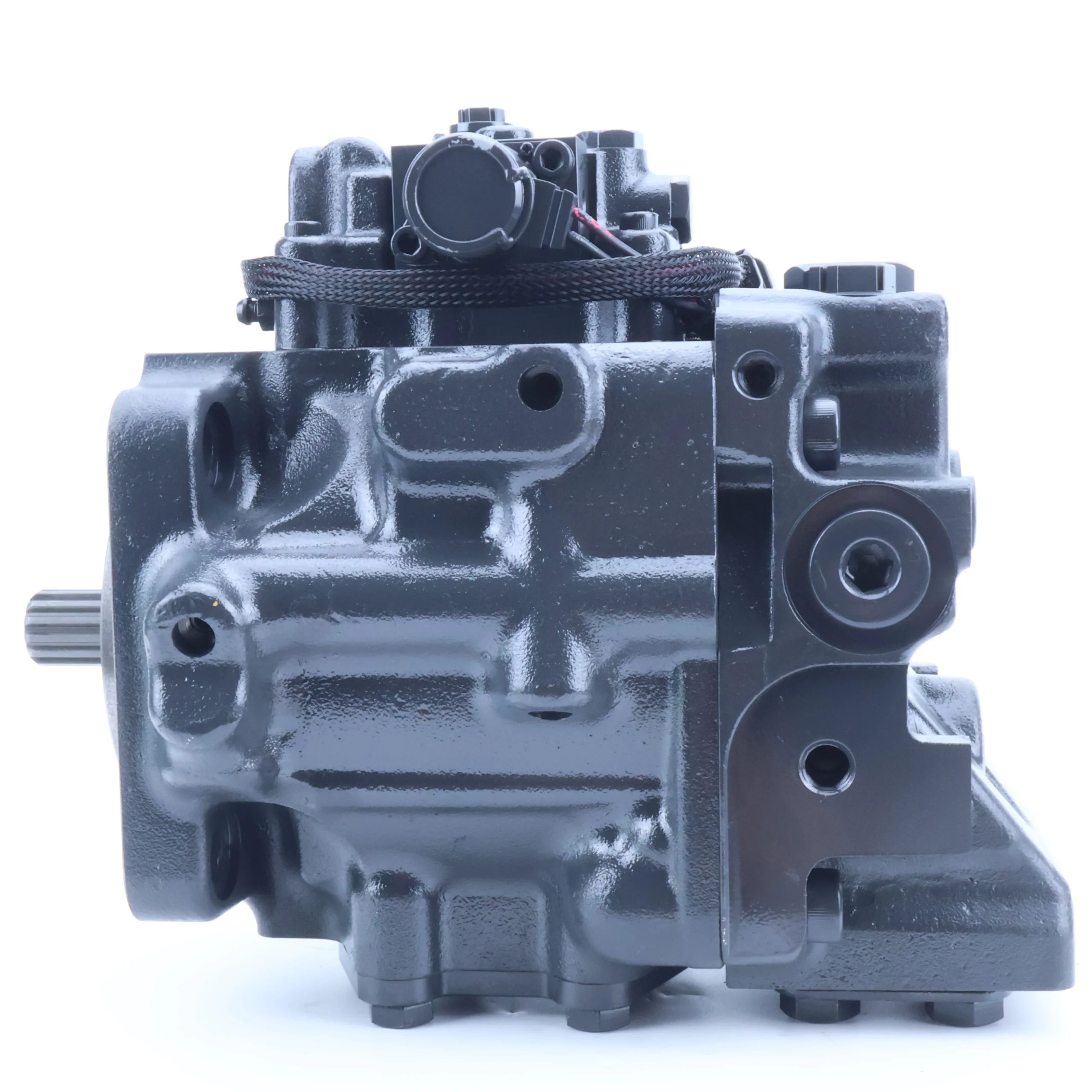
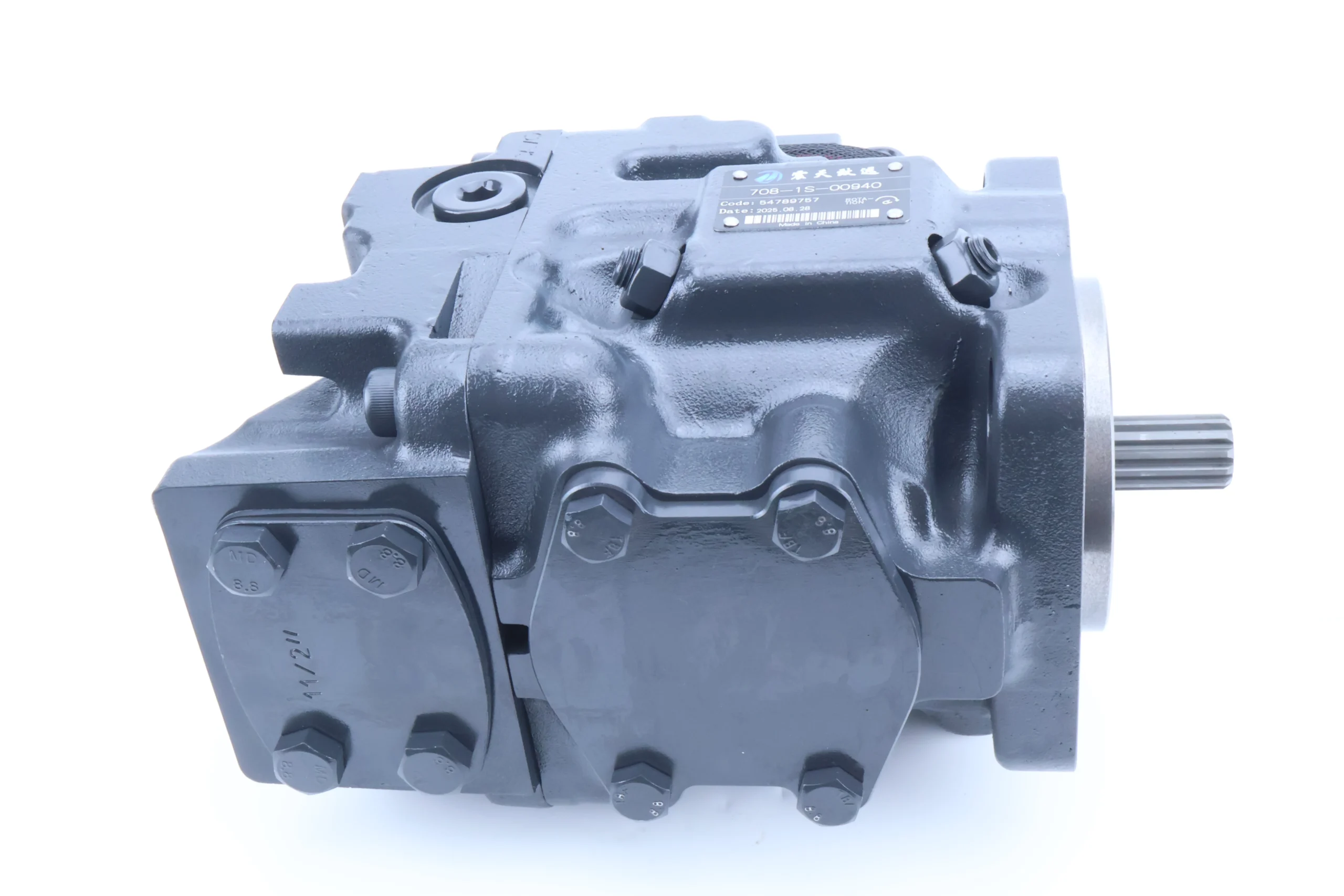
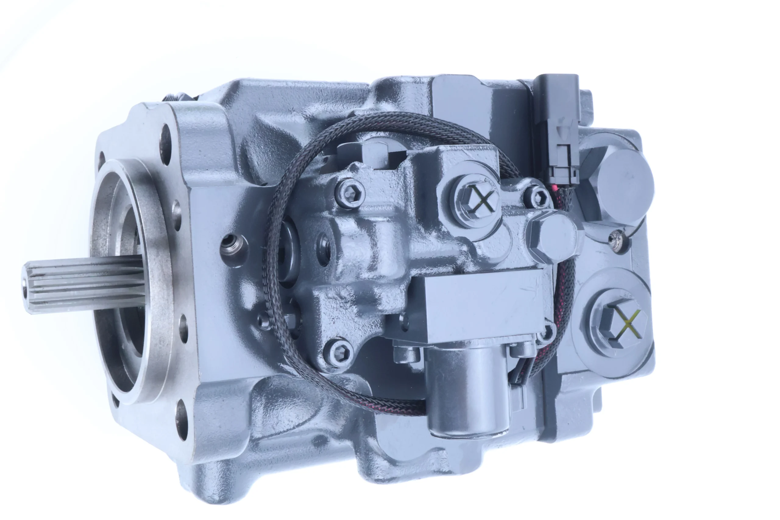
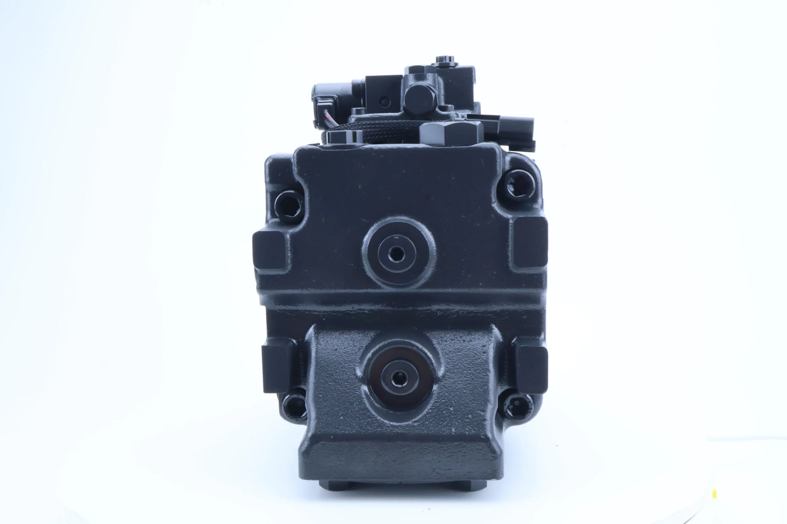


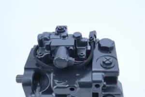
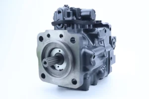
708-1S-00241 708-1S-00240 708-1T-00630 7081S00940 Hydraulic Piston Pump Fan Pump for WA380-6 Loader Pump 708 708-1S 708-1T
Displacement and pressure
Theoretical displacement: 70-80 mL/r (milliliters per revolution), which belongs to the medium displacement specification and is suitable for the power requirements of medium-sized hydraulic systems.
Rated pressure: 25-31.5 MPa (250-315 bar), capable of withstanding long-term cyclic heavy-load operations. Instantaneous peak pressure: 35 MPa (350 bar), single duration ≤10 seconds, capable of withstanding start-up shock or sudden load changes.
2. Speed range
Rated speed: 1500-2500 rpm, with excellent matching performance with the output speed of medium-sized engines and industrial motors.
Maximum allowable speed: 3000 rpm, minimum stable speed ≤80 rpm, pressure fluctuation error under low-speed conditions ≤1.5%.
3. Structural form
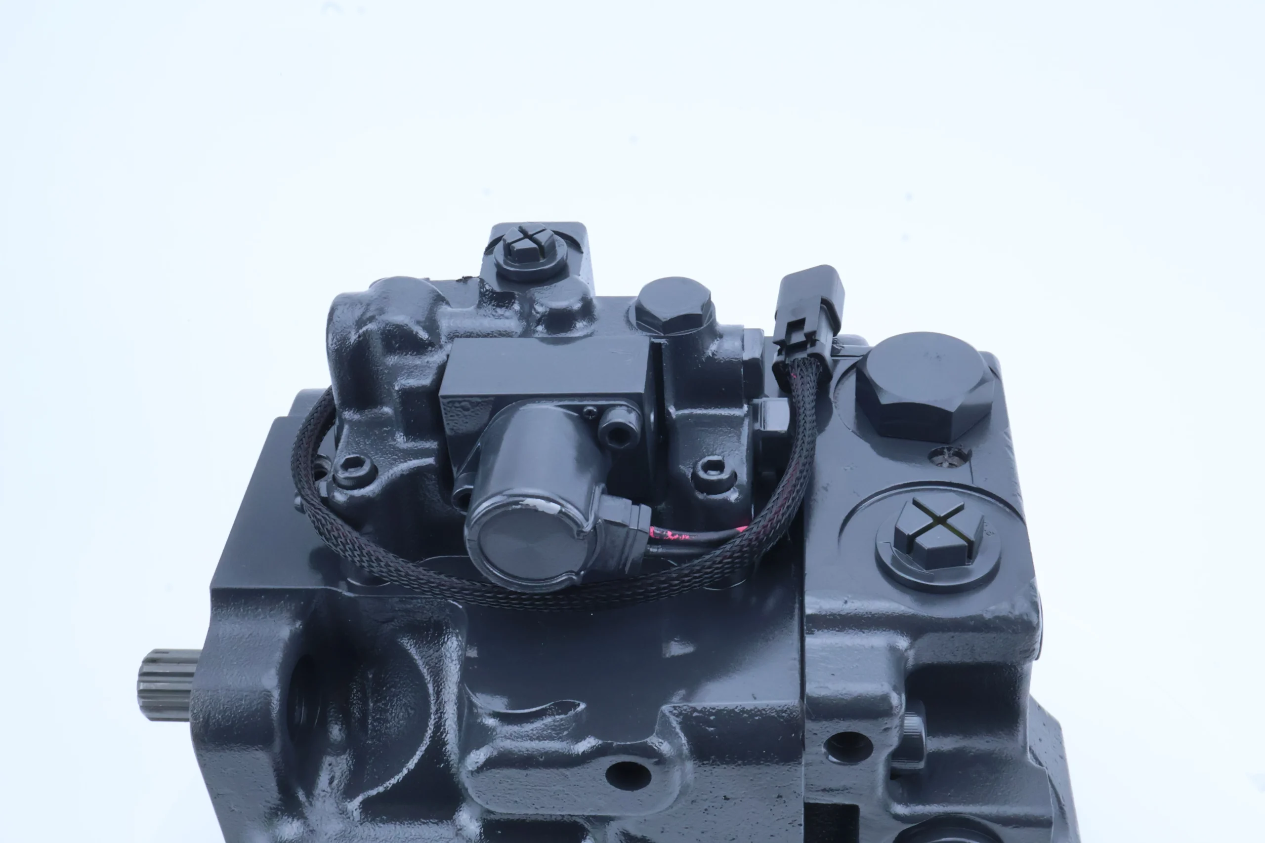
Type: Axial piston variable pump (may integrate constant power or load sensitive control mechanism), the piston is made of nitrided alloy steel, the cylinder body is high-strength forged aluminum alloy, and the oil distribution plate is copper-based wear-resistant alloy.
Sealing configuration: Double-lip skeleton oil seal + integrated pressure compensation valve, suitable for high-pressure environments (the “S” mark may correspond to the high-pressure stage).
4. Oil requirements
Applicable oil type: L-HM 46 or 68 anti-wear hydraulic oil is recommended. For cold regions (below -30℃), L-HV 68 low-temperature anti-wear hydraulic oil should be selected, with a viscosity range of 15-400 mm²/s.
Working oil temperature: -20℃ to 80℃. The oil cleanliness should reach ISO 16/13 grade (NAS 7 grade). A 10μm high-pressure filter is installed at the oil inlet, and a 20μm fine filter is added at the oil return port.
5. Installation and adaptation
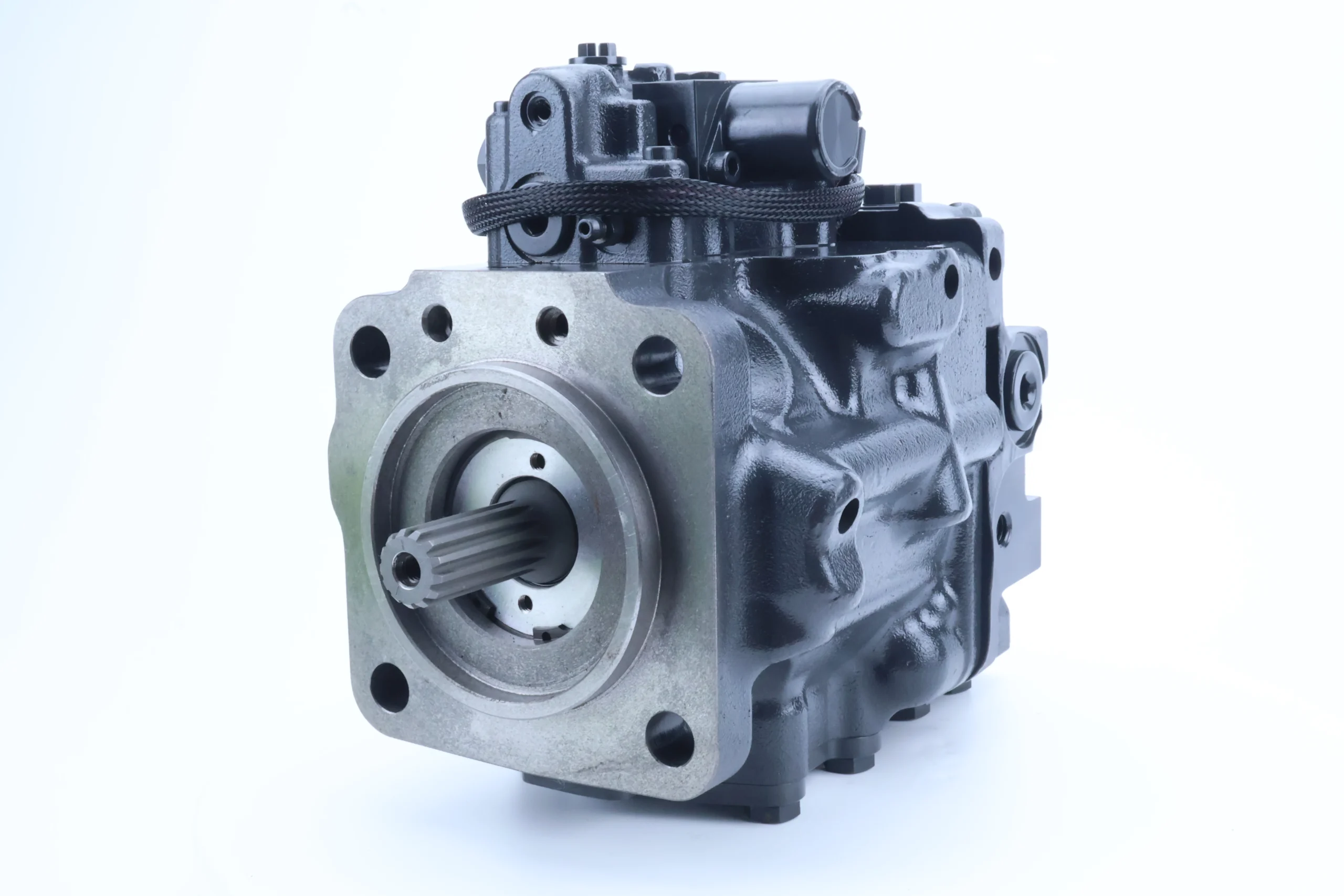
Installation type: SAE C3 flange installation, shaft end with Φ45mm flat key connection, keyway specification 14× 9mm, positioning pin diameter Φ8mm, shell sealing adopts fluororubber O-ring.
Oil port specifications: Suction port G2.5, pressure port G2, supports unidirectional rotating oil supply, overall weight approximately 30-35kg, recommended for horizontal installation (tilt Angle ≤15°).
6. Other parameters
Volumetric efficiency ≥95% (under rated conditions), total efficiency ≥91%, no-load noise value ≤83 dB (at 2000 rpm), radial runout at the shaft end ≤0.1 mm, working life ≥ 12,000 hours (under rated conditions).Ii. Working Principle
Power transmission and plunger movement
The power source (engine, motor) drives the transmission shaft to rotate through a coupling, which in turn rotates the cylinder block synchronously. Under the action of centrifugal force and return spring, the ball head of the plunger always adheres closely to the surface of the swash plate, forming a stable force transmission structure.
Due to the inclined Angle of the swash plate, the plunger rotates along with the cylinder block and moves back and forth in a straight line along the cylinder block holes. When it moves from the lower position to the higher position of the swash plate, it extends out of the cylinder block, increasing the volume of the sealed cavity to form a vacuum, and then sucks oil through the oil suction window of the oil distribution plate. Conversely, when moving from a high position to a low one, the cylinder retracts, the cavity volume shrinks, and the oil is squeezed and output to the system through the pressure oil window.
2. Variable adjustment mechanism
Constant power control: When the system pressure rises to the set threshold (such as 25 MPa), the constant power mechanism pushes the swash plate to reduce the tilt Angle and lower the displacement to maintain power stability and prevent engine overload.
Load sensitive control: Real-time collection of the load pressure of the actuator. When the load decreases, the swash plate Angle is quickly increased through pressure feedback to enhance the displacement and meet the flow demand, achieving “on-demand fuel supply”. Compared with single-variable mechanisms, it saves 20% to 25% of energy.
3. Pressure compensation and stable output
The built-in pressure compensation valve balances the intake oil pressure and system pressure in real time. When the load suddenly changes and causes pressure fluctuations, the compensation valve quickly adjusts the opening degree of the valve core to stabilize the rate of change in the swash plate Angle and avoid system shock caused by sudden changes in displacement.
Iii. Product Features and Advantages
1. High-pressure wear resistance and reliability
The surface hardness of the plunger is HV900-1000. The fit clearance between the cylinder body and the plunger is controlled within 0.005-0.01mm. The volumetric efficiency is ≥95%, and the energy loss during long-term operation is low. Under a rated pressure of 31.5MPa, the working life exceeds 12,000 hours, which is 30% longer than that of ordinary plunger pumps.
2. Dynamic response and energy efficiency
The load-sensitive response time is ≤50ms. It only takes 0.3 seconds to switch from low speed and small flow to high speed and large flow, which is 40% faster than the response speed of traditional pumps. The annual energy-saving cost of compound variable regulation is reduced by 20% to 25% compared with traditional quantitative pumps.
3. Wide operating condition compatibility
The oil temperature range of -20℃ to 80℃ covers most working environments, and the wide viscosity range of 15-400mm²/s is suitable for different regional climates. With a speed range of 80 to 3000rpm and a power source of 100 to 200 horsepower, it is suitable for low-speed precise fine-tuning (such as fixture clamping) to high-speed heavy-load (such as loader lifting).
4. Integration and convenient maintenance
It integrates functions such as constant power, load sensitivity, and pressure compensation, and its volume is 40% smaller than that of the split solution. The modular design enables individual replacement of vulnerable parts, reducing maintenance time to within one hour.
Iv. Usage Functions and Purposes
1. Usage function
Power output: As the core power source of the medium-sized hydraulic system, it outputs high-pressure oil at 31.5MPa to drive the actuating elements to perform heavy-duty actions such as lifting, digging, and pressing.
Energy-saving and precise control: The compound variable regulation enables pressure and flow to be matched as needed, with a pressure fluctuation error of ≤1.5%, and the operation accuracy is improved (for example, the error of the pressing force of the press is ≤2%).
Continuous operation guarantee: It can operate continuously for 24 hours under rated working conditions, making it suitable for long-term operation scenarios such as mines and infrastructure construction.
2. Uses
Construction machinery: Main hydraulic system for 15-25-ton class excavators, oil supply for lifting/tipping buckets of 10-15-ton class loaders, and oil supply for luffing/telescopic of 8-12-ton class hydraulic cranes.
Industrial and special machinery: Power source for 800-1500-ton hydraulic presses, drive for medium-sized underground loaders in mines, and fuel supply for lifting small container cranes in ports.
V. Applicable Machines and Scenarios
1. Applicable machines
Construction machinery: 15-25 ton excavators, 10-15 ton loaders, 8-12 ton cranes, medium-sized road rollers.
Industrial equipment: Hydraulic presses, metallurgical roll adjustment devices, small cranes for ports.
2. Applicable scenarios
Medium and heavy-load compound operation: continuous excavation and rotation by excavators, loading and unloading and walking by loaders. The 31.5MPa pressure and 71L/min flow rate meet the multi-action coordination, and the operation efficiency is increased by 35%.
Harsh environments: underground rock powder in mines, dust at construction sites, salt spray environments in ports. Strong anti-pollution performance (compatible with ISO 16/13 grade oils) can extend the maintenance cycle to over 1,500 hours.
Six. Similar models
1. Models of the same series
708-1S-00970: Its parameters are similar to those of 708-1S-00940, but its rated pressure may be higher (35 MPa), making it suitable for extremely heavy-load scenarios in mines.
708-1S-01940: With different displacement or control methods, it is suitable for medium-sized loaders or bulldozers.
2. Similar alternative models
A4VSO71DR/31R-PPB13N00: Axial piston variable pump, displacement 71 mL/r, electro-hydraulic proportional variable control, suitable for industrial scenarios requiring precise flow regulation.
PVH106QIC-RF-1S-10-C25-31: High-pressure plunger pump, displacement 71 mL/r, dual oil distribution plate structure, shock resistance 25% higher than 708 series, suitable for mining equipment.
Vii. Precautions for Use
1. Oil management
Strictly use L-HM 46/68 or L-HV 68 anti-wear hydraulic oil. It is prohibited to mix different brands and grades. Before changing the oil, flush the pump chamber and pipelines with new oil (the flushing oil volume should be no less than 1.5 times the system volume).
The cleanliness of the 10μm filter at the oil inlet should be checked every 800 hours, and the 20μm fine filter at the oil return port should be replaced every 1200 hours. Hydraulic oil should be replaced every 2,000 to 2,500 hours, and the moisture content of the oil should be no more than 0.1%.
2. Installation and alignment
Elastic couplings are adopted for connection. The coaxiality error of the two shafts is ≤ 0.15mm, and the angular error is ≤0.5°, avoiding the bending of the transmission shaft caused by radial force.
The diameter of the oil suction pipeline is ≥Φ60mm, the length is ≤2m, the number of elbows is ≤2, and the oil suction resistance is ≤0.02MPa (anti-cavitation).
3. Startup and operation monitoring
Before the first start, fill with clean hydraulic oil and manually turn the wheel 5 to 8 times. When starting at temperatures below -20℃, heat the oil to above -10 ℃ and run it at a low speed of 1000 RPM without load for 10 minutes. After the oil temperature reaches 30℃, gradually load it (at a rate of ≤5MPa/minute).
During operation, monitor the oil temperature at 30-85℃, the pressure at ≤31.5MPa, and the leakage at the shaft end at ≤5 drops per minute. In case of abnormal noise, sudden drop in pressure or oil temperature ≥95℃, stop the machine immediately for inspection.
4. Maintenance and care
Check the shaft seal every 1000 hours. Replace the fluororubber double-lip oil seal if the leakage exceeds the standard. Disassemble and inspect every 6,000 hours. Replace the plunger when the scratch is greater than 0.02mm or the flatness error of the oil distribution plate is greater than 0.01mm.
Calibrate the compound variable mechanism every 2000 hours to ensure that the displacement adjustment error is ≤2% and the pressure and flow matching is precise.
5. Security and Storage
Before maintenance, cut off the power source, release the pressure to 0MPa, and ensure the oil temperature is no more than 40℃ before disassembling. If the machine is to be shut down for a long time (more than 3 months), drain the oil, inject anti-rust oil, seal the oil port shaft end, and store it in a dry environment with a humidity of no more than 60%.


