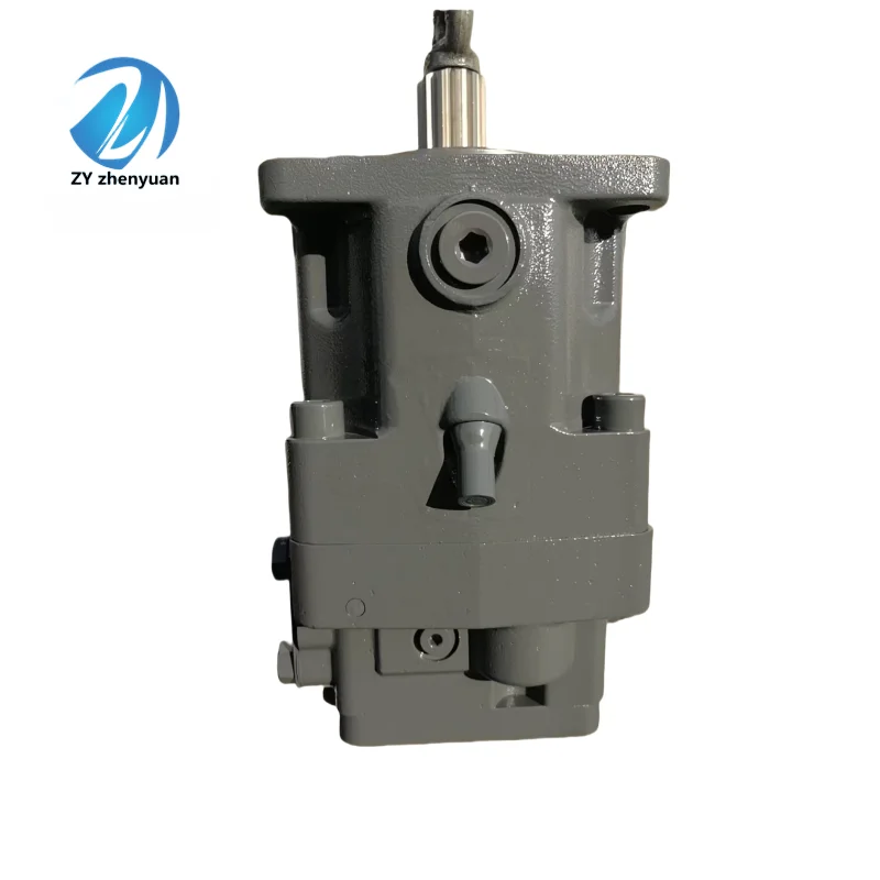


A11VO Hydraulic Pump 95 130 190 145 75 260 Series A11VO95HD2/10R-NZD12K01 Hydraulic Axial Piston Variable Displacement Pump
1. Basic performance parameters- Pump body type: Open-circuit axial piston variable pump, swash plate structure, integrated hydraulic control variable system and high-pressure protection valve group, supports unidirectional rotation, suitable for medium and high-pressure hydraulic transmission systems
– Displacement and pressure parameters: Rated displacement 95 cc/rev (core parameter indicated on the model), variable range 0-95 cc/rev continuously adjustable; Rated working pressure: 350 bar, maximum allowable pressure: 400 bar (short-term tolerance: ≤10 seconds, suitable for heavy-load impact conditions); The back pressure of the return oil is ≤5 bar, the pressure at the drain port is ≤2 bar, and the pressure difference of the hydraulic control variable is ≤18 bar
– Rotational speed and flow parameters: Rated rotational speed 1800 rpm (compatible with standard industrial power sources), maximum rotational speed 2350 rpm (short-term ≤5 minutes), minimum stable rotational speed 500 rpm; The maximum output flow at the rated speed is 171 L/min (95 cc/rev×1800 rpm÷1000), the flow pulsation rate is ≤2.5%, and the response time of the hydraulic control variable is ≤200 ms
– Efficiency parameters: Rated working condition volumetric efficiency ≥95%, total efficiency ≥88%; The control power consumption of the hydraulic control system is ≤300 W, and the system pressure loss at the rated flow is ≤5 bar
2. Structure and connection parameters
– Structural type: High-strength cast iron pump body (tensile strength ≥300 MPa), surface cathodic electrophoresis anti-corrosion treatment; The 9 plungers are evenly distributed in the cylinder body. The alloy steel plungers (hardness HRC62-65) are nitrided, and the surface of the swash plate is high-frequency quenched (hardness HV850-900). The static pressure balanced distribution plate is equipped with a self-lubricating coating and is supported by double-row tapered roller bearings. The combination of mechanical seal and fluororubber lip seal is adopted, with a static leakage rate of ≤1.5 mL/min. Integrated shock-proof buffer valve
– Installation and connection specifications: Flange installation complies with SAE J744-hole standard, output shaft is flat key connection (specification 14× 35mm, conforming to ANSI B92.1 standard); Oil port thread specifications: Suction port G1½, outlet port G1, hydraulic control interface X1 is G1/4. The overall weight is approximately 54 kg, and the external dimensions (length × width × height) ≈420×240×230 mm. It supports through-shaft drive design
– Protection grade: IP65, dust-proof and water-proof, suitable for dusty and medium to low vibration (vibration acceleration ≤ 10g) environments in industrial workshops, supports horizontal axial installation
3. Medium and Environmental requirements
– Medium requirements: Compatible with L-HM 46/68 anti-wear hydraulic oil. L-HM 32 low pour point type can be selected for low-temperature working conditions. The allowable medium viscosity range is 7-400 mm²/s, and the optimal working viscosity is 14-50 mm²/s. The moisture content should be ≤0.02%, and the degree of solid particle contamination should reach ISO 4406 14/11 grade
– Environmental parameters: Working environment temperature -30℃ to 80℃, ideal working oil temperature 50±4℃; Storage temperature: -40℃ to 100℃, relative humidity: ≤95% (no condensation). In harsh working conditions (such as in mines and metallurgy), the oil cleanliness needs to be improved to grade 13/10
– Filtration requirements: A coarse filter screen of ≥80 mesh must be installed on the oil suction side. A high-pressure filter with an accuracy of ≤10 μm should be added to the oil outlet. A magnetic filter with a filtration accuracy of ≤25 μm should be equipped on the oil return side. It is recommended that the system integrate an oil contamination degree monitoring interface
Ii. Working Principle
This pump is a swashplate axial plunger hydraulic variable pump. Its core achieves efficient conversion of mechanical energy and hydraulic energy through “plunger reciprocating volume change + hydraulic swashplate Angle adjustment”, and is adapted to dynamic load conditions with multiple protection mechanisms. The specific operation mechanism is as follows:
1. Core mechanism of power transformation
The motor or engine drives the transmission shaft to rotate the cylinder block synchronously. Under the combined action of the thrust from the inclined surface of the swash plate and the return spring, the plunger moves back and forth along the plunger holes of the cylinder block in a straight line. When the plunger rotates with the cylinder body to the oil suction zone, the plunger extends outward, increasing the volume of the plunger hole and creating a negative pressure vacuum environment. The hydraulic oil is then sucked in through the oil suction port, the coarse filter screen and the oil suction chamber of the distribution plate. When the plunger rotates to the oil pressure zone, the swash plate forces the plunger to retract inward, causing the volume of the plunger hole to sharply shrink. The oil is compressed to generate high pressure, which is then guided to the hydraulic actuator (cylinder, motor, etc.) through the oil pressure chamber of the distribution plate and the high-pressure filter, completing the conversion of mechanical energy into hydraulic energy and outputting power. The output flow rate is positively correlated with the inclination Angle of the swash plate. The greater the inclination Angle, the longer the plunger stroke, and the greater the output flow rate.
2. Hydraulic control variables and protection mechanisms
The HD2 type hydraulic variable mechanism is adopted. A pilot pressure of ≥4 bar is input through the X1 control port to drive the variable piston to move along the axis. The piston drives the swash plate to deflector around the fulcrum through the connecting rod mechanism, achieving stepless displacement adjustment from 0 to 95 cc/rev. The system integrates a pressure cut-off function. When the output pressure rises to the rated value of 350 bar, the hydraulic control valve automatically fine-tune the inclination Angle of the swash plate to maintain pressure stability. When the pressure exceeds the maximum limit of 400 bar, the variable mechanism quickly reduces the inclination Angle of the swash plate to the minimum, and at the same time, the high-pressure relief valve opens to unload, guiding the oil back to the oil tank. The double protection prevents the pump body and pipelines from overloading. The static pressure balanced distribution plate can automatically compensate for the wear clearance, always maintaining a close fit with the cylinder body, ensuring that the volumetric efficiency remains stable at a high level for a long time.
Iii. Product Features and Advantages
– High efficiency, energy conservation and precise control: The hydraulic variable control system can adjust the displacement in real time according to the load demand. When the load is light, it automatically reduces the displacement to lower energy consumption, saving more than 30% energy compared with the fixed displacement pump. The pressure control accuracy reaches ±2 bar, and the flow regulation response time is ≤200 ms. It is suitable for working conditions with frequent load changes, such as press pressurization and compound actions of excavators
– High pressure resistance and long service life: Designed with a rated pressure of 350 bar, it is suitable for medium and high pressure system requirements, and has a short-term pressure resistance capacity of 400 bar to handle shock loads. The plunger and swash plate are made of high-strength wear-resistant materials and coated with a self-lubricating coating. The wear is ≤ 0.02mm per 10,000 hours, and the rated working condition fault-free operation life is ≥ 15,000 hours. The 9-plunger uniform distribution design reduces flow pulsation, and the operating noise at 1 meter is ≤78 dB
– Compact structure and flexible expansion: The unit power density is 15% higher than that of products in the same level, and the compact size is suitable for equipment with limited installation space. The through-shaft drive design supports the integration of a gear pump or a plunger pump of the same specification at the rear end of the output shaft, achieving multi-loop power supply and simplifying the system layout. With an IP65 protection rating, it is suitable for dusty and water-splashing environments, and is applicable to both industrial and construction machinery scenarios
– Easy maintenance and wide adaptability: The modular valve group design ensures that the core component replacement time is no more than 1 hour, and basic maintenance can be completed on-site. It supports the replacement of multiple control methods such as DR (constant voltage), LR (constant power), and EP (electrical proportional), and can be adapted to different brands of engines or motors through adapter parts, reducing the cost of equipment upgrades
Iv. Usage Functions and Purposes
1. Core usage functions
– Stepless variable oil supply: By precisely regulating the output flow through the pilot pressure signal, it can continuously change from 0 to 171 L/min, meeting the different speed requirements of the actuator, such as the switch between the rapid advancement of the injection molding machine during mold closing and the slow operation during pressure holding
Constant pressure stable control: After setting the working pressure, the system can automatically balance the relationship between flow and pressure. The pressure fluctuation is ≤2 bar, which is suitable for constant pressure demand scenarios such as press pressing and precision press-fitting, ensuring processing accuracy
– Overload safety protection: Dual protection mechanisms of pressure cut-off and relief valve enable rapid unloading when the load is overloaded or the pipeline is blocked, preventing damage to the pump body, motor and pipeline, and reducing the cost of fault maintenance
– Multi-loop integrated drive: With the through shaft drive function, it can simultaneously provide power for multiple independent hydraulic circuits, such as driving the boom, bucket arm and slewing mechanism of an excavator at the same time, reducing the number of power sources and saving installation space
2. Main uses
As a core power component of medium and high-pressure hydraulic systems, it is used to convert the mechanical energy of motors or engines into hydraulic energy, providing stable power for the actuating elements. It is widely adaptable to equipment with frequent load changes and high requirements for pressure/flow control accuracy. It is a key component in fields such as construction machinery, industrial manufacturing, and metallurgical processing, and is particularly suitable for hydraulic systems that require energy conservation, consumption reduction, and precise control.
V. Applicable Machines and Scenarios
1. Adapt to the core machine
– Construction machinery: Main hydraulic systems for 6-20 ton crawler excavators, steering and lifting systems for small and medium-sized loaders, conveying mechanisms for concrete pump trucks, hoisting and luffing mechanisms for truck cranes, power systems for hydraulic drilling RIGS
– Industrial machinery: 500-1000 ton medium-sized presses, 200-500 ton injection molding machine clamping and injection systems, rolling mill roll gap adjustment mechanisms, heavy-duty machine tool worktable feed systems, die-casting machine injection systems
– Special equipment: Vibration system for continuous casting molds in metallurgical equipment, propulsion mechanism for mine tunnel boring machines, drive system for deck cranes on ships, power source for hydraulic test benches
2. Typical application scenarios
– Excavator compound action scenario: Compatible with the main pump of a 12-ton excavator, when simultaneously performing the compound action of the boom lifting and bucket harvesting, the hydraulic control system completes the flow distribution within 180 ms. The lifting circuit achieves a flow rate of 90 L/min, and the bucket harvesting circuit achieves a flow rate of 60 L/min. When excavating hard rock under heavy load, the pressure rises to 350 bar, and the displacement automatically maintains 95 cc/rev to output the maximum power. When transferring under light load, the displacement drops to 30 cc/rev, and the combined fuel consumption is reduced by 28%
– Medium-sized press stamping scenario: Equipped with a 630-ton press, during the rapid downward stage, it outputs a large displacement of 95cc /rev with a flow rate of 171L /min, achieving rapid positioning within 1.5 seconds. During the pressurization stage, it automatically reduces to a small displacement of 25 cc/rev, maintaining a constant pressure of 320 bar, with a pressure holding accuracy of ±1%. The energy consumption per shift is 35% lower than that of traditional fixed displacement pumps
– Metallurgical rolling mill control scenario: For the 1200mm cold rolling mill roll gap adjustment system, the hydraulic variable control system adjusts the flow rate in real time based on the feedback signal of the rolling thickness to ensure that the roll gap adjustment accuracy is ≤ 0.05mm. The system pressure is stabilized at 280 bar, and the oil temperature during continuous rolling is controlled within 65℃. The equipment has been operating continuously for over 12,000 hours without failure
Six. Similar models
1. Different models of the same series displacement
-A11VO75HD2/10R-NZD12K01: Rated displacement: 75 cc/rev, rated speed: 1800 rpm, flow rate: 135 L/min, rated pressure: 350 bar. Suitable for medium and small-sized equipment such as 5-15 ton excavators and 300-500 ton presses. Weight: approximately 48 kg, volume reduced by 12% compared to the original model
-A11VO130HD2/10R-NZD12K01: The rated displacement is 130 cc/rev, the rated speed is 1800 rpm, the flow rate is 234 L/min, and the maximum pressure is 400 bar. It is suitable for large equipment such as 20-30 ton excavators and 1000-1500 ton presses. The power is 37% higher than the original model, and the weight is approximately 68 kg
-A11VO40HD2/10R-NZD12K01: Rated displacement 40 cc/rev, rated speed 1800 rpm, flow rate 72 L/min, rated pressure 350 bar, suitable for light-load equipment such as small construction machinery and machine tool auxiliary systems. It weighs only 32 kg and has a more compact structure
2. Models with the same displacement but different functions
-A11VO95DR /10R-NZD12K01: Constant pressure control type. Once the system pressure reaches the set value, it automatically reduces the displacement to the minimum value required for pressure maintenance. It is suitable for scenarios with constant pressure requirements such as clamping devices and hydraulic test benches. The control accuracy is ±1 bar, and the cost is 15% lower than that of the hydraulic control type
-A11VO95LR /10R-NZD12K01: Constant power control type, with output power maintained at a constant level. The pressure and flow rate have an inverse hyperbolic relationship, which can fully utilize the power of the power source. It is suitable for construction machinery with large load fluctuations such as loaders and bulldozers, and the energy-saving effect is improved by 10%
-A11VO95EP /10R-NZD12K01: Electric proportional control type, supports 4-20mA or 0-10V electrical signal input, flow regulation accuracy ±0.5%, can be integrated with PLC system to achieve automatic control, suitable for intelligent production lines and precision processing equipment, cost 40% higher than hydraulic control type
A11VLO190DR/11R-NPD12N00 A11VLO190DRG/11R-NPD12N00 A11VLO190DRS/11R-NPD12N00 A11VO190DR/11R-NPD12N00 A11VO190DRG/11R-NPD12N00
A11VO190DRS/11R-NPD12N00 A11VLO190EP2/11R-NPD12N00 A11VLO190LRDU2/11R-NZD12K02P-S A11VLO190LRDU2/11R-NZD12K83P
A11VLO190LRDU2/11R-NZD12K84P A11VLO190LRDS/11R-NSD12K01 A11VLO190LRDS/11L-NSD12K01 A11VLO190LE2S/11R-NZG12K04
A11VLO190LRDH2/11R-NZD12K02 A11VLO190LRDH2/11R-NZD12K01 A11VLO260DR/11R-NZD12N00 A11VLO260DR/11R-NPD12N00
A11VLO260DRG/11R-NPD12N00 A11VLO260DRS/11R-NPD12N00 A11VO260DR/11R-NPD12N00 A11VO260DRG/11R-NPD12N00 A11VO260DRS/11R-NPD12N00
A11VLO260EP2/11R-NPD12N00 A11VLO2600LRDU2/11R-NZD12K02P-S A11VLO260LRDU2/11R-NZD12K84P A11VLO2600LRDH2/11R-NZD12K02
A11VO145LRDS/11R-NZD12N00 A11VO145LRDS/11R-NZD12K83 A11VLO145LRDS/11R-NSD12K02 A11VLO145LE2S/11R-NZG12K07
A11VLO145LE2S/11R-NZG12K04 A11VLO145LE2S/11R-NZG12K01 A11VO145LRDS/11L-NZD12N00 A11VO145LRDS/11L-NZD12K83
A11VLO145LRDS/11R-NZD12K01-Y A11VLO145LE2S/11L-NZD12K01P A11VLO145LRDS/11R-NZG12K07 A11VLO130LRDU2/10R-NZD12K02P-S
A11VLO130LRDH1/10R-NZD12K61 A11VLO130LRDH1/10R-NZD12K07 A11VLO130DRS/10R-NZD12K02 A11VLO130LRDS/10R-NSD12K02
A11VO130LRDS/10R-NZD12K07 A11VLO130LE2S/10L-NZD12K02P-K A11VO95LRDS/10R-NSD12N00 A11VO95LRDS/10R-NZD12K02
A11VO95LRDU2/10R-NZD12K02 A11VO95LRDS/10L-NSD12N00 A11VO95EP2D/10R-NZD12N00 A11VO95EP2D/10R-NZD12N82P A11VO75LRDS/10R-NSD12N00
A11VO75DR/10R-NPD12N00 A11VO75DRS/10L-NZD12K02 A11VO60DRS/10R-NSC12N00 A11VO60LRDS/10R-NZD12N00 A11VO40DRG/10R-NZC12K02
A11VO40DRG/10R-NPC12N00 A11VLO190DR/11R-NZD12N00
Installation and commissioningWhen installing, it is necessary to ensure that the coaxiality error between the pump shaft and the drive shaft is ≤ 0.05mm. Elastic couplings should be used for connection. Rigid connection or direct radial force (≥ 120N) acting on the pump shaft is strictly prohibited. The pump body fixing bolts are selected as 8.8 grade high-strength bolts, with a pre-tightening torque of ≥80 N·m to prevent loosening caused by vibration
The oil suction pipeline should follow the principle of “short, straight and thick” : length ≤1.5 meters, inner diameter ≥30 mm, and the distance from the oil suction port to the bottom of the oil tank ≥150 mm. The pipeline connection adopts high-pressure resistant sealing rings to ensure no air leakage. A vacuum gauge (≤0.015 MPa) needs to be installed on the oil suction side to monitor the vacuum degree to prevent cavitation
Before the first start-up, fill the pump chamber with clean hydraulic oil (about 1 L), and manually turn the machine 5-6 times to confirm that the plunger can extend and contract smoothly. The hydraulic control interface X1 needs to first establish a pilot pressure of 4-7 bar, then run it no-load at low pressure (50 bar) and low speed (1000 rpm) for 30 minutes. Gradually increase the pressure and speed to the rated parameters, and at the same time calibrate the variable mechanism and the pressure set value
A heat dissipation space of ≥ 250mm and a maintenance space of ≥ 150mm should be reserved around the pump body. When the ambient temperature exceeds 45℃, a forced cooling device should be installed. Before starting in northern winter, the hydraulic oil should be preheated to above 10℃ to avoid increased viscosity at low temperatures, which may cause starting wear
2. Operation and Maintenance
During operation, key parameters need to be monitored in real time: pump body temperature (normal ≤80℃, maximum ≤95℃), outlet pressure (fluctuation ≤5 bar), and operating noise (≤78 dB). In industrial scenarios, inspections should be conducted every 4 hours, and in construction machinery, every 2 hours. If there is a sudden temperature rise exceeding 10℃, abnormal pressure or sudden noise changes, the machine should be stopped immediately for investigation
– Regular maintenance cycle: Under normal working conditions, replace the hydraulic oil and the three-stage filter every 2,000 hours. Replace every 1,000 hours in harsh working conditions such as mines and metallurgy. Disassemble and inspect every 8,000 to 10,000 hours. Replace the plunger when the diameter wear is ≥ 0.03mm and the surface scratch of the swash plate is ≥ 0.02mm. At the same time, replace the sealing parts and the return spring. Calibrate the pressure protection valve group every 1500 hours
It is strictly prohibited to run the engine without oil (idling for more than 3 seconds may cause the plunger and cylinder block to be scratched). Continuous operation at a maximum pressure of 400 bar is prohibited (for no more than 10 seconds at a time). When adjusting the displacement, it should be operated under low pressure (≤50 bar) to avoid mechanism jamming caused by adjustment under high pressure. Before shutting down, it should be reduced to low pressure and run no-load for 5 minutes. When the oil temperature is ≤60℃, the power should be cut off
3. Storage and Protection
When stored for a long time (more than 30 days), seal all oil ports with special plugs, inject special anti-rust oil (about 500 mL) into the pump cavity, and apply lithium-based grease to the keyway of the output shaft. Store in a dry and well-ventilated warehouse with a temperature ranging from 0 to 40℃ and a humidity of no more than 60%. Avoid direct sunlight, heavy object compression and oil contamination. Manually turn the wheel once every month and adjust the variable mechanism back and forth once
Before being put into use after being idle for more than 12 months, the pump cavity and pipelines must be thoroughly cleaned and all seals replaced


2.We has now developed into an international trading company that supplies various hydraulic machinery parts, oil pumps and valves.
3.Professional team and injectionmolding equipment.
4.In quality , quality management procedures are carried out in accordance with international standards and are implemented throughout the production process.
5.High quality service, and ensure timely delivery.
6.There is a perfect after-sale system.


