

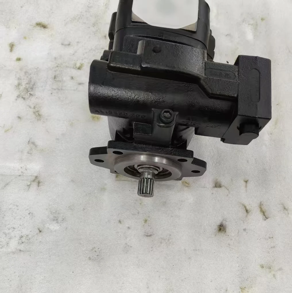

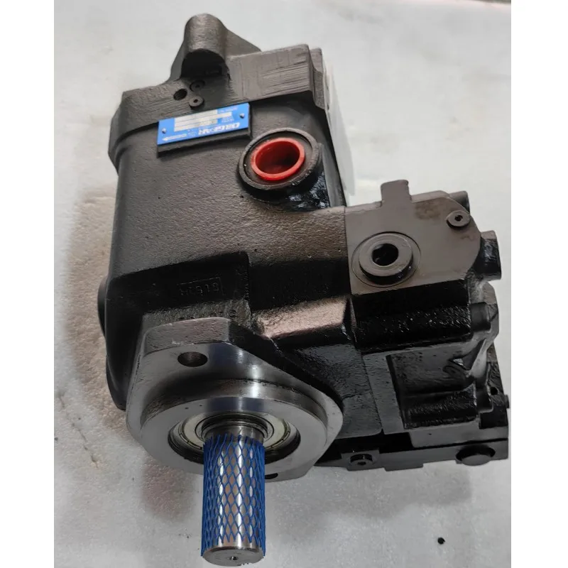
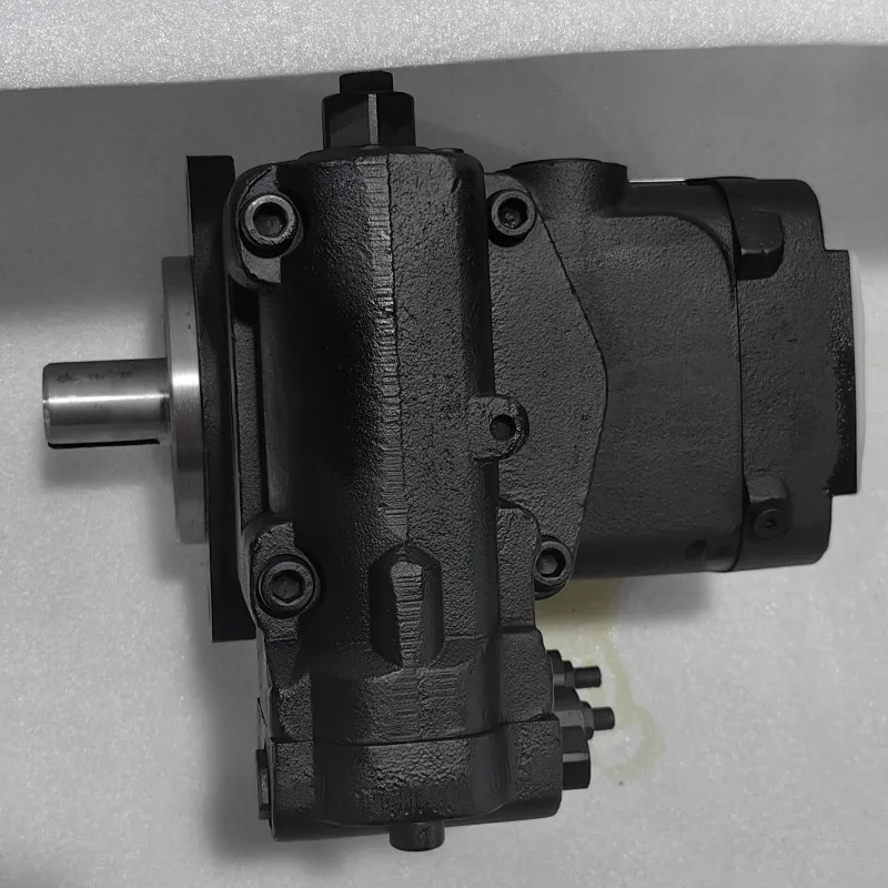
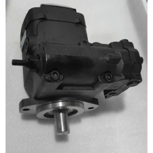
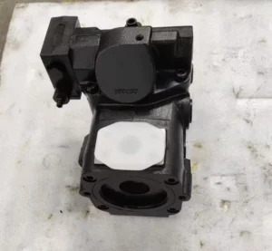


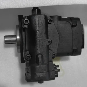
Hot Sell at Hydraulic Piston Pump AT180926 AT186167 AT197383 AT172064 AT172603 High Pressure Piston Oil Pump
•
Displacement: Based on the model specifications of the same series, the theoretical displacement is approximately 110 mL/r, which belongs to medium and large-sized displacement specifications and is suitable for medium and high-pressure high-flow working conditions.
•
Working pressure: Rated working pressure 28 MPa (280 bar), peak pressure up to 35 MPa (350 bar), with stable high-pressure output capability, suitable for heavy-duty load scenarios.
•
Speed range: Rated speed 1500 rpm, maximum speed 2500 rpm, minimum stable speed no less than 80 rpm, compatible with continuous operation at medium and high speeds and smooth operation at low speeds.
•
Control mode: Integrates dual control of load sensitivity (LS) and pressure compensation, supports optional electro-hydraulic proportional regulation, and can dynamically adjust the displacement in real time according to the system load, adapting to the collaborative working conditions of multiple actuating elements.
•
Structural form: Swash plate axial piston structure, single cylinder block multi-piston configuration, adopts integral pump casing design, key friction pairs are precisely ground.
•
Oil requirements: Anti-wear hydraulic oil with viscosity ranging from 15 to 400 mm²/s is suitable. The working oil temperature range is from -15℃ to 85℃, and the oil cleanliness must reach NAS level 8 (ISO 18/14).
•
Installation and adaptation: The shaft ends are connected by flat keys, and the shaft diameter complies with the ISO 3019-2 standard. The flange connection complies with the SAE J518C specification. The oil port is arranged at the tail end and supports horizontal installation.Ii. Working Principle
This plunger pump adopts a swashplate axial plunger structure. Its core components include the drive shaft, cylinder block, plunger, swashplate, oil distribution plate and load-sensitive control valve group. During operation, the prime mover drives the drive shaft to rotate the cylinder block at high speed. Under the combined action of centrifugal force and the return disc, the spherical ends of the evenly distributed plungers inside the cylinder block always closely adhere to the outer surface of the swash plate. Due to the inclination Angle between the swash plate and the cylinder block axis, the plunger moves back and forth along the cylinder bore axis during the rotation of the cylinder block. When the plunger rotates to the high side area of the swash plate, the squeezing effect of the swash plate causes the plunger to move towards the interior of the cylinder block. The volume of the sealed cavity formed by the plunger and the cylinder bore decreases, and the oil pressure inside the cavity increases. The oil is then pushed out of the system through the oil discharge window of the oil distribution plate, completing the oil pressing process. When the plunger rotates to the lower side area of the swash plate, the return force pushes the plunger to extend out of the cylinder block, increasing the volume of the sealed cavity and creating a local vacuum. Under the action of atmospheric pressure, the oil in the oil tank is sucked into the cavity through the oil suction window of the oil distribution plate, completing the oil suction process.
The load-sensitive control mechanism detects the system load pressure in real time through pressure sensors. When the load increases, the control valve group pushes the swash plate to increase the tilt Angle, the plunger stroke extends, and the displacement increases simultaneously. When the load decreases, the inclination Angle of the swash plate reduces, and the displacement decreases accordingly, achieving a precise match between the flow rate and the load. The pressure compensation function serves as an auxiliary protection. When the system pressure reaches the set threshold, it automatically limits the increase in displacement to prevent overpressure operation.
Iii. Product Features and Advantages
•
Strong adaptability to high pressure and large flow: The parameter combination of a rated pressure of 28 MPa and a displacement of 110 mL/r can stably output high pressure and large flow power, meeting the requirements of medium and heavy-duty hydraulic systems in 20-30 ton class construction machinery and other applications.
•
Outstanding performance in high efficiency and energy conservation: The typical value of volumetric efficiency is ≥94%, and the total efficiency is ≥90%. Load sensitive control can effectively reduce energy waste in “high flow and low load” scenarios, and the system temperature rise is reduced by more than 15%.
•
Anti-pollution and high reliability: The plunger and cylinder bore are designed with optimized clearance sealing, and the oil distribution plate is made of wear-resistant alloy material. Combined with a double-lip dust-proof sealing structure, it has excellent resistance to solid particle contamination and a service life of over 6,000 hours in dusty working conditions.
•
Rapid control response: The load-sensitive control response time is ≤0.3 seconds, and the displacement adjustment range is 5%-100%. It can quickly adapt to load fluctuations and ensure the coordination and smoothness of the actions of multiple actuators.
•
Good maintenance convenience: It adopts a modular pump core design. After wear, the pump core assembly can be replaced separately without disassembling the entire pump body. The key seals are of standardized specifications, with clear replacement cycles and relatively low maintenance costs.
Iv. Usage Functions and Purposes
1. Usage function
As the core power source of the hydraulic system, it converts the mechanical energy of the prime mover (motor, engine) into the pressure energy of the hydraulic oil, providing high-pressure oil for the actuating components such as hydraulic cylinders and hydraulic motors, and driving the equipment to achieve linear or rotational movements such as digging, lifting, rotating and squeezing. Through the coordinated control of load sensitivity and pressure compensation, dynamic flow distribution and pressure protection for multiple actuating elements are achieved, ensuring the operational efficiency and safety of the system under complex working conditions.
2. Uses
It is widely applied in medium and high-pressure high-flow hydraulic systems, covering fields such as construction machinery, industrial manufacturing, mining machinery, and port machinery. It provides stable power support for the core working mechanisms of equipment, especially suitable for scenarios with high requirements for power output stability and energy efficiency.
V. Applicable Machines and Scenarios
1. Applicable machines
•
Construction machinery: 20-30 ton excavators, medium-sized loaders, crawler cranes, main power units of hydraulic crushing stations.
•
Industrial equipment: Medium-sized injection molding machines (800-1200 tons), hydraulic presses (300-500 tons), roller drive systems for metallurgical production lines.
•
Mining and port machinery: Hoisting and luffing mechanisms for small mining excavators and port container handling machines.
•
Special equipment: Main hydraulic power units for large pavers and rotary drilling RIGS.
2. Applicable scenarios
It is suitable for high-pressure and high-flow, medium and heavy-duty loads, and multi-actuator collaborative operation conditions, such as earthwork excavation and material transfer in construction, large-scale injection molding and metal stamping in factory workshops, small-scale tunneling and crushing operations in mines, and container loading and unloading in ports. It is especially suitable for continuous operation scenarios where strict control over equipment energy consumption and large fluctuations in working conditions and loads are required.
Six. Similar models
This model belongs to the AT series swash plate axial piston pump. Similar models are mainly distinguished by displacement, pressure rating and control mode. Common ones include:
•
AT172054: Displacement 90 mL/r, rated pressure 28 MPa, control mode consistent with AT172064, suitable for small flow medium and high pressure systems.
•
AT172074: Displacement 130 mL/r, rated pressure 28 MPa, peak pressure 35 MPa. It is a high-flow model in the same series and is suitable for high-flow high-pressure systems.
•
AT172064-P: Consistent with the target model in terms of displacement and pressure, it features standard electro-hydraulic ratio control and is suitable for automated scenarios with higher requirements for flow accuracy.
•
Similar alternative models: A series 110 displacement plunger pumps (such as A110-30), with the same structural principle, rated pressure of 31.5 MPa, suitable for working conditions with higher pressure requirements.
Vii. Precautions for Use
•
Oil management regulations: Strictly select anti-wear hydraulic oil with a viscosity of 20-200 mm²/s. It is strictly prohibited to mix oils of different brands or grades. A ≥100 μm screen filter is installed at the oil suction port, and a 25 μm fine filter is added to the return oil pipeline. The contamination degree of the filter element is checked every 500 hours, and the hydraulic oil is replaced and the oil tank is cleaned every 2000 to 3000 hours.
•
Installation accuracy requirements: Connect to the prime mover with an elastic coupling. The coaxiality error of the two shafts should be ≤ 0.1mm, and the angular error should be ≤0.5° to avoid excessive radial force causing premature wear of the drive shaft bearings. The length of the oil suction pipeline shall be no more than 1.5m, and its diameter shall not be less than that of the pump’s oil suction port to reduce oil suction resistance and prevent cavitation.
•
Start-up and operation monitoring: Before the initial start-up, the pump body should be filled with clean hydraulic oil, and the pump body should be manually turned by hand for 3 to 5 turns to ensure there is no jamming. When starting, run it at low speed (800 rpm) without load for 10 minutes. After the oil temperature rises above 30℃, gradually increase the load to the rated pressure. During operation, monitor the oil temperature (30-70℃ is the best, and the maximum should not exceed 85℃) and pressure (it is strictly prohibited to exceed the rated pressure for a long time). If any abnormal noise, leakage or sudden drop in pressure occurs, stop the machine immediately for inspection.
•
Maintenance and care nodes: Check the sealing condition of the shaft seal every 1000 hours. When the leakage exceeds 3 drops per minute, the seal needs to be replaced. Disassemble and inspect the oil distribution plate, plunger and other friction pairs every 3,000 hours. If there are scratches on the surface or the wear exceeds 0.03mm, timely repair or replacement is required. Before long-term shutdown (more than 30 days), drain the oil in the pump or inject anti-rust oil, and seal the oil port to prevent impurities from entering.
•
Control parameter setting: The parameters of the load sensitive valve and the pressure compensation valve must be set by professionals according to the working conditions. It is strictly prohibited to arbitrarily increase the pressure or flow limit values. After replacing the control module, parameter calibration is required to ensure that the control signal is linearly matched with the displacement output and to avoid system shock.


2.We has now developed into an international trading company that supplies various hydraulic machinery parts, oil pumps and valves.
3.Professional team and injectionmolding equipment.
4.In quality , quality management procedures are carried out in accordance with international standards and are implemented throughout the production process.
5.High quality service, and ensure timely delivery.
6.There is a perfect after-sale system.


