


Hot Sell AT172603 at Hydraulic Pump AT180926 AT186167 AT197383 High Pressure Piston Pump AT302661 Oil Pump
Core performance parameters
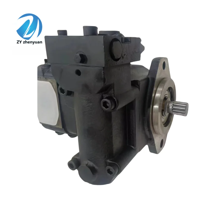
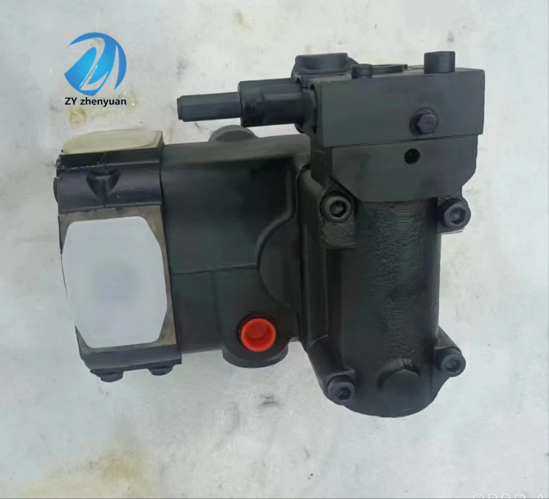
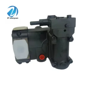
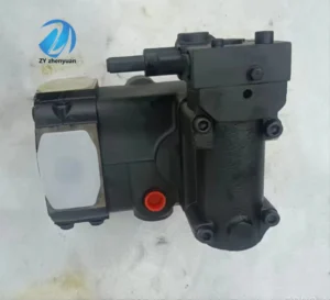
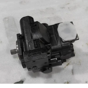
– Pump type: Axial variable piston pump, swash plate structure, right-rotating steering, suitable for high-pressure open hydraulic circuits, supports stepless displacement adjustment, providing high-pressure stable oil supply for light to medium and small-sized heavy-duty single actuators.
– Displacement and pressure parameters: Rated displacement 17 mL/r (estimated based on model “17”); Rated working pressure: 31.5 MPa, maximum allowable pressure: 35 MPa (for a duration of ≤10 seconds); Rated speed: 1500 r/min, maximum speed: 2000 r/min (short time ≤5 minutes).
– Flow and efficiency parameters: Maximum flow at rated speed of 25 L/min, variable range 0-25 L/min continuously adjustable; Volumetric efficiency ≥92%, total efficiency ≥84%; The flow regulation accuracy is ±3%.
– Operating characteristics: Continuous operating oil temperature ≤85℃, rated working condition inlet vacuum degree ≤ 0.025MPa; Noise value ≤81 dB (measured at 1 meter); The fault-free operating life under rated conditions is ≥ 10,000 hours.
2. Structure and connection parameters
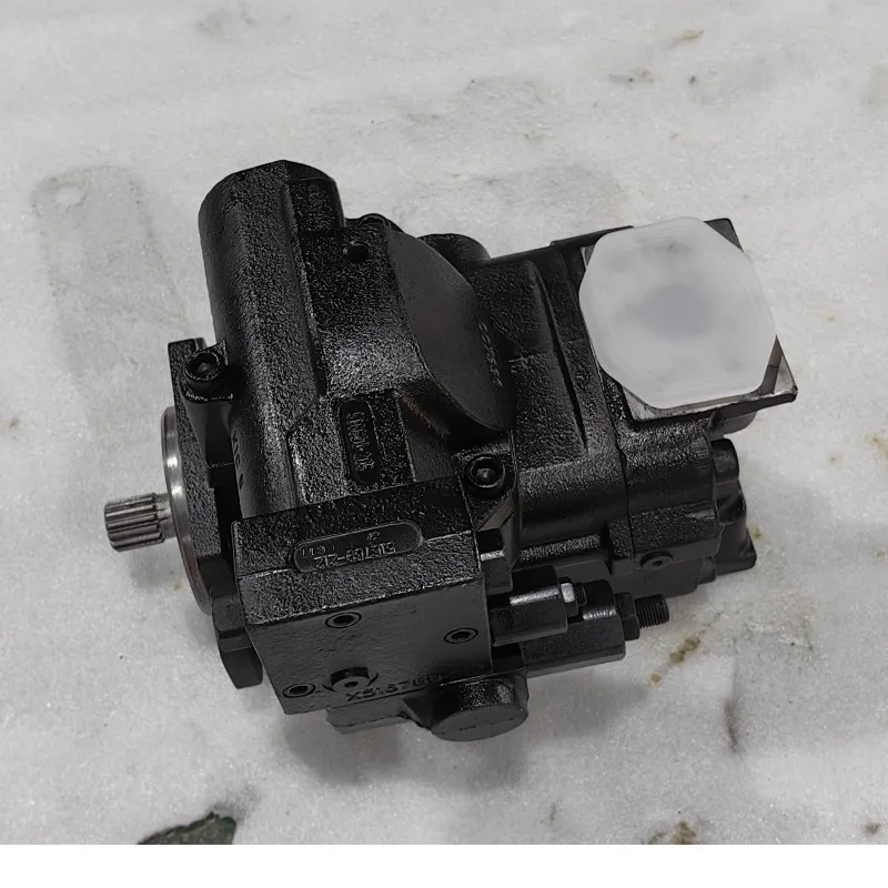
– Structural type: Swash plate axial plunger structure, integrating a single plunger cylinder body, variable swash plate, return plate and built-in high-pressure relief valve; It adopts constant power + load sensitive compound control and supports dual adjustment of manual and hydraulic pilot. Flange installation design, equipped with a high-efficiency oil-absorbing filter screen.
– Core material: The plunger is made of stainless steel 17-4PH (quenched and tempered, hardness HRC40-43); The cylinder block is made of alloy cast iron QT500-7 (aged treatment). The swash plate is made of bearing steel GCr15 (quenched treatment). The sealing part is a high-pressure resistant fluororubber combination (temperature resistance ≤110℃).
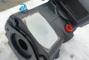
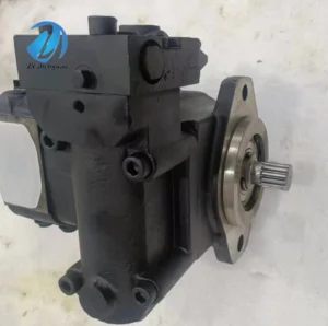
– Connection specifications: The oil suction port (S) is a DN50 flange, and the oil outlet port (P) is a DN40 flange. The drive shaft is spline connected (specification: 8×30×35). Install flange bolts with a center distance of 150×100 mm. The weight of the pump body is approximately 55 kg, and its external dimensions (length × width × height) ≈420×260×300 mm.
3. Medium and Environmental requirements
– Medium requirements: L-HM 46/68 anti-wear hydraulic oil is suitable for normal temperature, and L-HM 32 is selected for low-temperature environment; The allowable medium viscosity is 20-400 mm²/s, and the moisture content is ≤0.03%. It is strictly prohibited to use media containing solid particles (particle size > 5 μm) or corrosive media.
– Cleanliness standard: The oil cleanliness should reach ISO 4406 15/12 grade. A 5 μm fine filter should be placed in front of the oil suction port. The filter should be replaced immediately when the pressure difference of the filter is greater than 0.06 MPa.
– Environmental parameters: Operating environment temperature -20℃ to 90℃, relative humidity ≤95% (short-term condensation is allowed); With a protection grade of IP54, it is suitable for scenarios such as light construction machinery, industrial hydraulic stations, and small mining equipment.Ii. Working Principle
This pump is a swashplate type axial variable piston pump. The core achieves high-pressure oil supply through the mechanism of “piston reciprocating volume change – swashplate Angle adjustment of displacement – load adaptation pressure control”. The specific process is as follows:
1. Core process of oil suction and discharge
The drive shaft rotates the cylinder block at high speed. Under the combined action of the spring force of the return disc and the hydraulic force, the plunger inside the cylinder block is always in close contact with the surface of the swash plate. When the plunger rotates with the cylinder block to the side of the swash plate that is farther from the center, the plunger extends outward, increasing the volume of the plunger chamber in the cylinder block and creating a negative pressure. Hydraulic oil is then drawn into the chamber through the suction port and the filter screen. When the plunger rotates to the side of the swash plate closer to the center, the inclined surface of the swash plate compresses the plunger to retract inward, causing a sharp reduction in volume. The oil is then discharged from the oil outlet under high pressure, completing the continuous oil suction and discharge cycle.
2. Variables and Safety Protection
– Stepless variable regulation: The variable mechanism is controlled by the load sensitive valve to change the inclination Angle of the swash plate (adjustable from 0 to 14°). An increase in the Angle leads to an increase in the plunger stroke and flow rate, while a decrease in the Angle results in a decrease in flow rate. The response time is ≤0.5 seconds, adapting to the dynamic changes in load requirements.
– Safety Assurance: Equipped with a built-in high-pressure relief valve, it automatically unloads when the system pressure exceeds 33 MPa, and the overpressure oil flows back to the oil suction chamber. Constant power control limits the maximum flow rate based on the power of the power source to avoid overload. The oil replenishment valve in the oil suction chamber prevents cavitation caused by excessive vacuum.
Iii. Product Features and Advantages
– Small displacement and high pressure compatibility: With a rated pressure of 31.5MPa and a displacement of 17 mL/r, as well as a maximum flow rate of 25 L/min, it precisely matches the single actuator of 10-25 ton class equipment, taking into account the flexibility of high-pressure power and flow regulation, and is suitable for light and heavy load scenarios.
– Load sensitive energy saving: Load sensitive control can dynamically output flow according to the demand of the actuator. The non-working flow can be reduced to below 2.5L /min, and the idle consumption is reduced by 35%. The pressure fluctuation under high-pressure conditions is ≤1.8%, making it suitable for single-action high-frequency operations.
– Anti-wear, reliable and durable: The plunger is precisely ground with the cylinder block, with a fit clearance of ≤ 0.008mm and a volumetric efficiency of ≥92%. The core components are made of reinforced materials that are wear-resistant and can withstand a short-term high-pressure impact of 35 MPa. The rated working condition fault-free operation life is ≥ 10,000 hours.
– Compact and easy to install: Integrates core components such as relief valves and oil replenishment valves, eliminating the need for additional valve groups; Weighing only 55 kg, it is 30% lighter than the split system of the same displacement. The installation size is suitable for the limited space of light equipment and supports quick assembly.
– Convenient operation and maintenance: External oil level observation window and pressure test interface, no need to disassemble the pump body for operation and maintenance. The wear parts have strong universality and are compatible with the mainstream small-displacement plunger pump accessories on the market, with relatively low annual maintenance costs.
Iv. Usage Functions and Purposes
1. Core usage functions
High-pressure variable oil supply: It provides adjustable flow rates ranging from 0 to 25 L/min for light-duty and heavy-duty systems, meeting the full working condition requirements from rapid action of the actuator (such as mold closing in small hydraulic presses), uniform operation (such as lifting in small loaders) to high-pressure pressure holding (such as in small forging).
– Dynamic load adaptation: Real-time monitoring of system load pressure, automatic adjustment of output flow to prevent excessive flow overflow loss, and adaptation to multi-stage operations of “no-load fast feed – heavy-load working feed – pressure holding” for a single actuator.
Single-pump single-loop drive: As the core power of the system, it provides a stable high-pressure oil source for a single heavy-duty actuator, enhances system integration, and reduces the configuration cost of the power end for light equipment.
2. Main application fields
In the field of light construction machinery: 10-25 ton wheel loaders (lifting circuits), 15-20 ton crawler excavators (auxiliary circuits), 50-80 ton truck cranes (luffing circuits), suitable for urban and rural infrastructure construction and small-scale construction site operations.
– Industrial equipment field: 300-800 ton small hydraulic presses (main cylinder circuit), medium-sized machine tool hydraulic systems (clamping circuit), 500-800 ton injection molding machines (mold closing circuit), suitable for medium and small tonnage precision operations in factories.
– Small-scale special fields: small-scale mining crushing stations (crushing hammer circuits), small-scale agricultural machinery (hydraulic drive circuits), 10-20 ton cranes in ports (lifting circuits), suitable for intermittent heavy-load operation scenarios.
V. Applicable Machines and Scenarios
1. Adapt to the core machine
– Light construction machinery: 10-25 ton wheel loaders, 15-20 ton crawler excavators, 50-80 ton truck cranes, small hydraulic crushing stations.
– Industrial equipment: 300-800 ton hydraulic presses, medium-sized CNC lathes, 500-800 ton injection molding machines, small forging machines.
– Small special equipment: small mine tunnel boring machines, hydraulic systems for large agricultural tractors, 10-20 ton gantry cranes for ports, small deck machinery for ships.
2. Typical application scenarios
– Loader operation scenario: As the main pump of the lifting circuit of a 20-ton wheel loader, it outputs a flow rate of 25 L/min when loading and unloading materials to drive the lifting cylinder to rise rapidly. When heavily loaded, it automatically drops to 12 L/min to maintain pressure, and the pressure is stable at 31.5MPa, which is 30% more energy-efficient than traditional pumps.
– Small hydraulic press forming scenario: It is used in a 600-ton factory hydraulic press. When closing the mold quickly, it outputs a flow rate of 25 L/min to improve efficiency. When pressing parts, it reduces to a small flow rate of 6 L/min for pressure holding (pressure 31.5MPa), which is suitable for the stamping forming requirements of metal parts.
– Small-scale crushing station scenario: It is equipped with a single crushing hammer crushing station for small-scale mines, providing 31.5MPa high-pressure oil for the crushing hammers. The flow rate is automatically adjusted according to the rock hardness (8-22 L/min), and the impact-resistant structure is suitable for stone crushing operations, meeting the mining needs of small-scale mines.
Six. Similar models
1. Alternative models of the same series
-AT122603: A small-displacement model of the same structure, with a rated displacement of 12 mL/r and a maximum flow rate of 18 L/min. The pressure parameters are consistent. It is suitable for 5-10 ton class light equipment (such as 10-ton loaders), and the cost is 18% lower than that of the original model.
-AT222603: A mid-displacement model in the same series, with a rated displacement of 22 mL/r and a maximum flow rate of 33 L/min. It has the same pressure parameters and is suitable for 25-30 ton class equipment (such as the main circuit of a 25-ton excavator). Its cost is 22% higher than that of the original model.
2. Cross-series alternative models
-AT172603-L: Left-rotating model, with exactly the same structure and parameters, suitable for power sources with left-rotating drive shafts (such as some small diesel engines), and the cost is the same as the original model.
-AT172603-H: High-temperature compatible model, with the temperature resistance of the sealing parts increased to 150℃, suitable for high-temperature working conditions of metallurgical auxiliary equipment, etc. The cost is 40% higher than that of the original model.
-AT172603-D: Quantitative version model, fixed displacement 17 mL/r, consistent pressure parameters, suitable for high-pressure systems with stable flow requirements (such as fixed-station hydraulic presses), with a cost 15% lower than the original model.
Vii. Precautions for Use
1. Medium management
At normal temperature, L-HM 46/68 anti-wear hydraulic oil is selected; at low temperature, L-HM 32 is selected. It is strictly prohibited to mix oils of different grades. Before the new pump is used for the first time, the pump body and pipelines should be flushed with clean oil in a circulating manner for ≥15 minutes to ensure that the cleanliness meets ISO 4406 15/12 grade.
– Check the pressure difference of the oil suction filter weekly (replace the filter element when it exceeds 0.06 MPa), test the moisture content of the oil monthly (≤0.03%), and take samples to test the cleanliness quarterly. When emulsification, discoloration or presence of metal impurities in the oil is detected, immediately stop the machine, change the oil and clean the pump body.
2. Installation and commissioning
When installing, ensure that the coaxiality of the drive shaft and the motor shaft is no more than 0.05mm (using an elastic coupling for positioning), and the flange bolts are evenly tightened with a torque of 350 N·m. The diameter of the oil suction pipeline should be no less than DN50, the length no more than 2.5m, and the number of elbows should not exceed 2 to avoid excessive oil suction resistance.
Before debugging, add hydraulic oil to the upper limit of the oil level gauge in the oil tank, and manually turn the wheel 3 to 5 times to confirm there is no jamming. Jog the motor to verify the rotation direction (right rotation), run it at low speed (1000 r/min) without load for 10 minutes, and then test the variable adjustment performance (no lag in flow regulation and stable pressure).
The oil suction port should be at least 400mm lower than the oil level in the oil tank, and a 0-40MPa high-pressure pressure gauge should be installed at the oil outlet. Install rain and dust covers outdoors to ensure that the protection level remains at IP54. After the hydraulic pipelines are connected, they need to be vented to prevent cavitation.
3. Operation and Maintenance
During operation, real-time monitoring of the pump body temperature (normal ≤80℃, maximum ≤90℃), outlet pressure and noise is carried out. If the temperature rises sharply by more than 15℃, the pressure fluctuates by more than 1.8MPa, or the noise abnormally increases (> 86dB), stop the machine immediately for inspection, with a focus on checking for oil contamination or plunger wear.
– Regular maintenance every 1500 hours: Clean the oil suction filter screen and relief valve, and check the fit clearance between the plunger and the cylinder block (replace the matching parts when > 0.015mm). Replace the high-pressure seals and hydraulic oil, and recalibrate the relief valve pressure to 33 MPa.
– Do not run without oil (running without oil for more than 3 seconds may cause the plunger to sinter). It is strictly prohibited to operate at an excessive speed (> 2000 r/min) or under long-term overpressure (> 35 MPa). When adjusting variables, avoid sudden changes in flow rate to prevent system shock from damaging the pipelines.
4. Storage protection
When stored for a long time, use special plugs to block the oil suction port and the oil outlet, inject anti-rust oil into the pump body, and apply grease to the splines of the drive shaft. Store in a dry warehouse with a temperature ranging from 0 to 45℃ and a humidity of no more than 60%. Avoid direct sunlight and heavy object compression. Manually turn the machine once a month to prevent component adhesion.
Before putting the pump into use after being idle for more than 18 months, thoroughly clean the inner cavity of the pump and replace all high-pressure seals. After adding new oil, conduct a low-speed trial run for 1.5 hours to test the variable performance and pressure stability. Once no abnormalities are confirmed, connect to the system.


