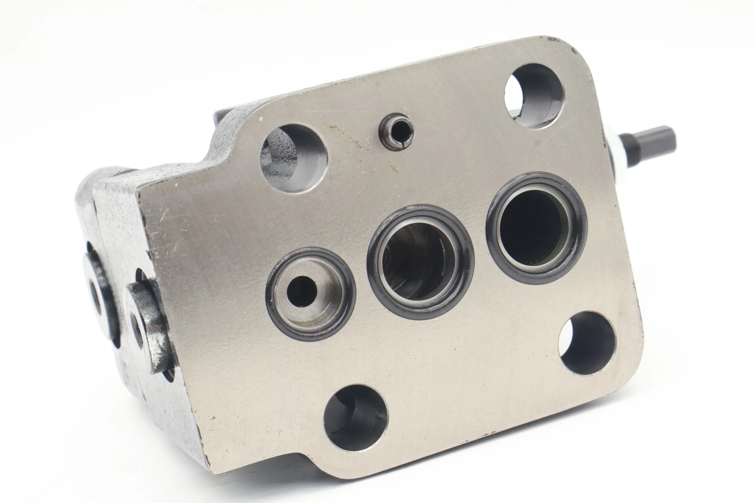
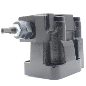
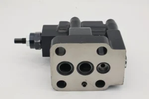
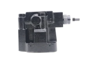

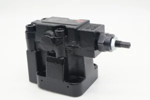

CG2V-6FW-10 Hydraulic Electro Proportional Valve CG2V CG5V XG2V Solenoid Valve CG2V-8-FW-10 Hydraulic Pressure Relief Valve
Basic specifications
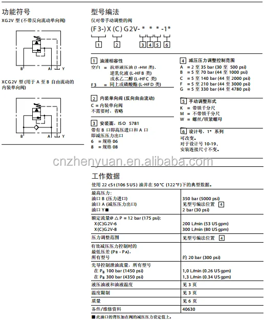
Type: CG2V series two-stage pilot-operated relief valve, 6 indicates the diameter, FW10 indicates the pressure regulation range (1000-3000 psi/69-207 bar)
Rated pressure: 350 bar (5000 psi), and the maximum working pressure shall not exceed this value
Maximum flow rate: approximately 22.7 L/min (6 US gpm), and some data indicate up to 120 L/min, depending on the model and application scenario
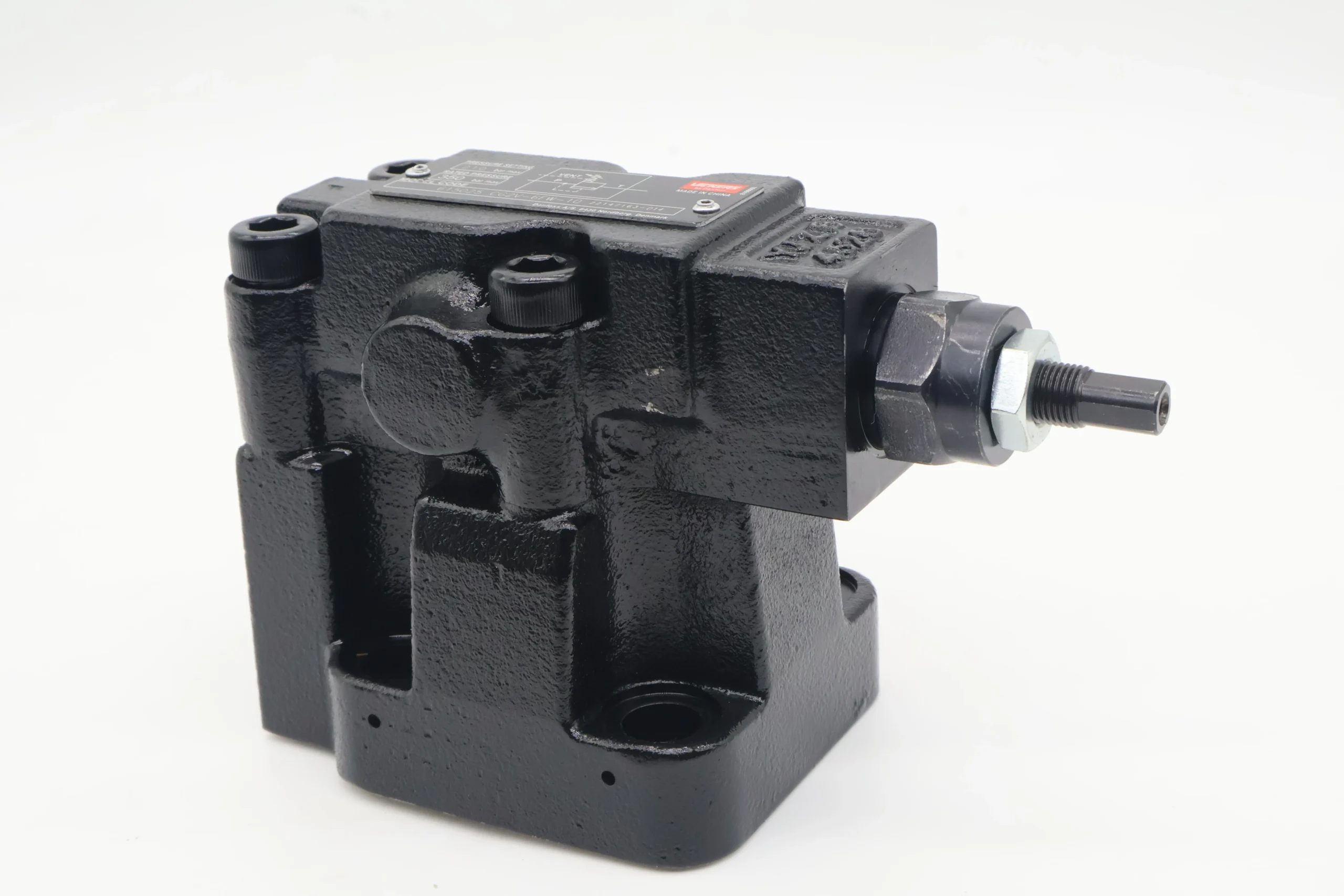
Adjustment range: 69-207 bar (1000-3000 psi). The system protection pressure can be precisely set through the adjustment handle
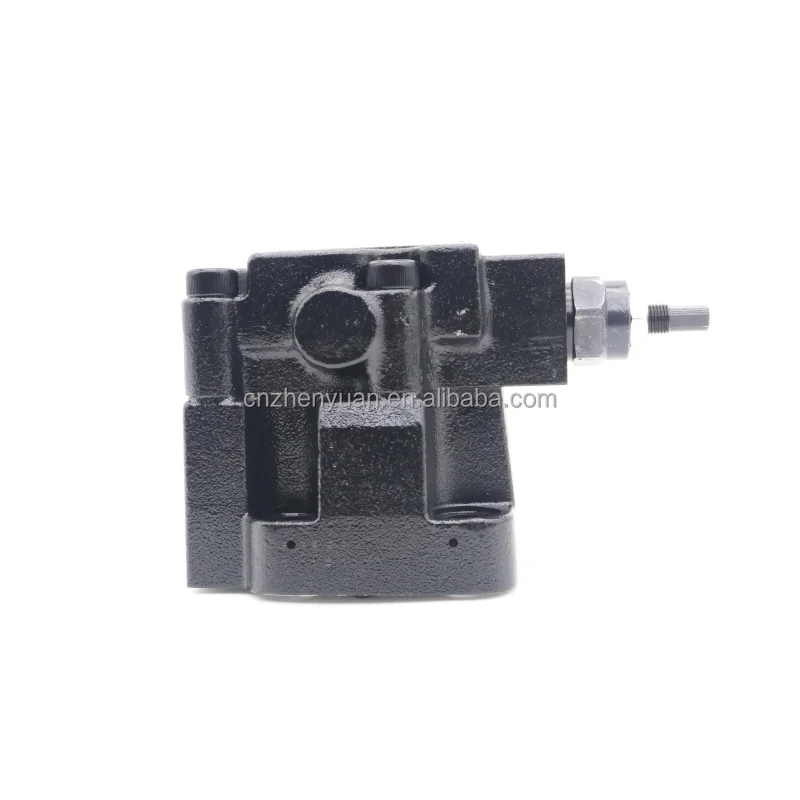
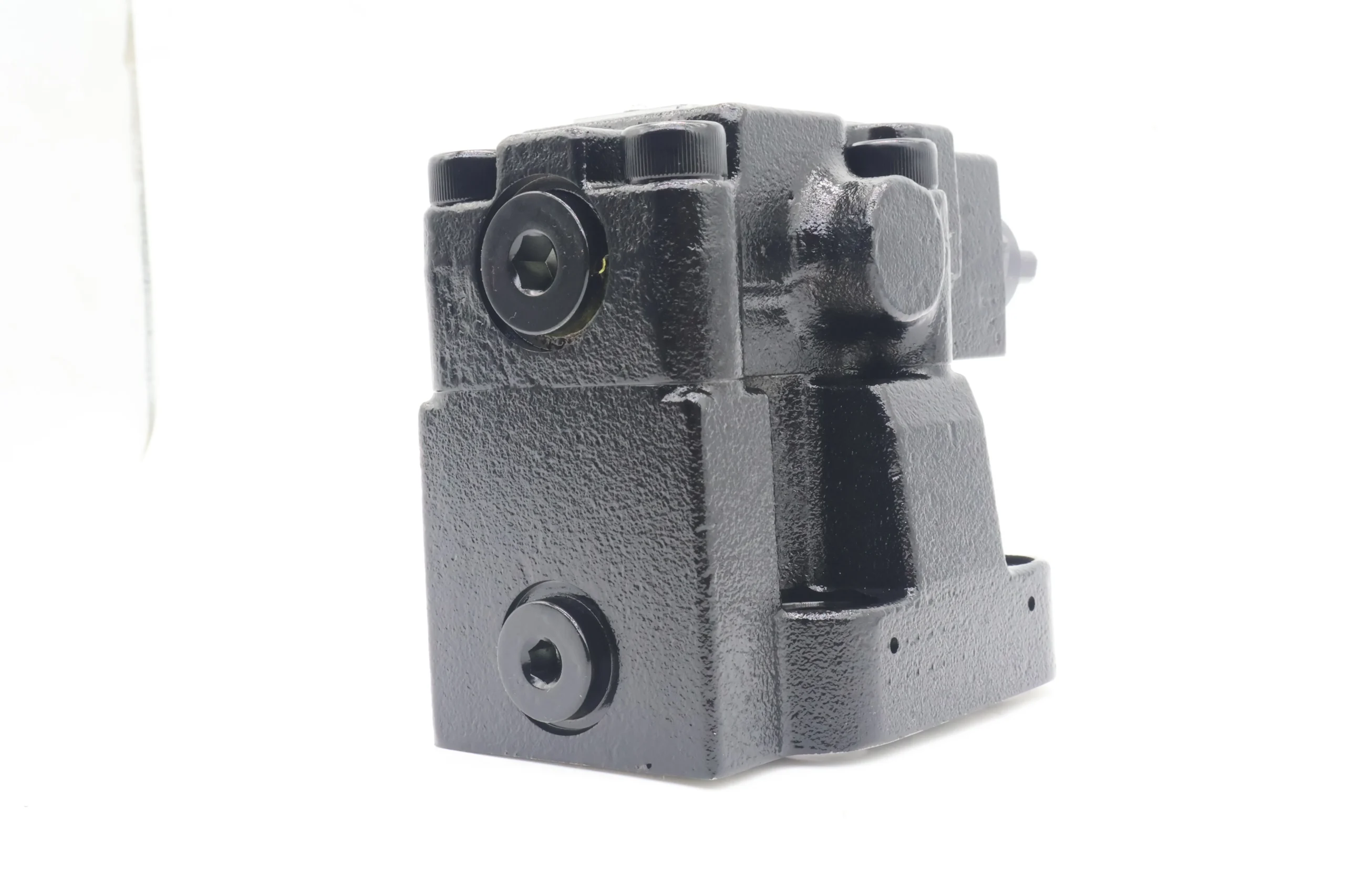
Connection method: Plate connection, standard interface, convenient for installation and maintenance
Weight: Approximately 2-3 kg, compact structure, suitable for hydraulic systems with limited space
Medium temperature: -20℃ to 70℃, recommended working temperature: 30-50℃. Avoid high-temperature environments affecting performance
Applicable oil: Mineral oil-based hydraulic oil, viscosity range 10-40 cSt (mm²/s), L-HM anti-wear hydraulic oil is recommended
Oil cleanliness: ISO 4406 18/15 grade. A 60-100 mesh oil filter protection valve core needs to be installed at the oil inletIi. Working Principle
Working mechanism of two-stage pilot-operated relief valve
Structural foundation
It is composed of two major parts: the pilot valve and the main valve. The pilot valve is responsible for precise pressure regulation, while the main valve is responsible for overflow pressure control
The main valve consists of the main valve core, the main valve spring and the damping hole. The pilot valve consists of a pilot valve core and a pilot spring
The valve body is equipped with a P port (oil inlet), a T port (oil outlet/return to the oil tank), and a remote control port (X port), enabling remote control or unloading
Work process
Closed state: When the system pressure is lower than the set value, the main valve core presses the valve seat under the action of the main valve spring, all oil ports are closed, and there is no overflow
When the system pressure rises, the oil enters from port P, passes through the radial hole of the main valve core → the damping hole → the upper chamber of the main valve core → the pilot valve chamber
Pilot opening: When the pressure reaches the set value, the hydraulic pressure overcomes the force of the pilot spring, and the pilot valve opens. A small amount of oil flows back to the oil tank through the pilot valve port
Main valve action: Due to the throttling effect of the damping hole, a pressure difference is formed between the upper and lower chambers of the main valve core. This pressure difference pushes the main valve core upward, opening the main valve port. A large amount of oil flows directly from port P to port T and returns to the oil tank, achieving overflow pressure relief
Pressure stability: When the system pressure drops slightly below the set value, the pilot valve closes, and the main valve core falls back under the action of the spring force, reducing overflow and maintaining the system pressure stable near the set value, with a fluctuation range of no more than ±3% of the set pressure
Control characteristics
Remote control: By connecting a remote pressure regulating valve to port X, remote adjustment of the system pressure can be achieved. Or connect an electromagnetic valve to achieve system unloading (when the electromagnetic valve is powered on, the system pressure drops to nearly zero)
Multi-level protection: Multi-level pressure protection can be achieved by connecting multiple relief valves in series. Different opening pressure values can be set to protect different circuits of the system
Iii. Product Features and Advantages
1. Precise pressure control capability
High-precision pressure stabilization: The pressure fluctuation is controlled within ±3% of the set value to ensure the stability of the system pressure and improve the movement accuracy of the actuator
Fine adjustment: Equipped with a dedicated pressure regulating handle, it can precisely set the system protection pressure, with high adjustment accuracy, making it suitable for precision hydraulic systems
Good opening and closing characteristics: The pilot-operated structure makes the valve open and close more smoothly, with small pressure lag (≤5% of the set pressure), reducing water hammer effect and system shock
2. Reliability and stability
Two-level protection design: The pilot valve opens first to detect pressure, while the main valve is responsible for large flow overflow. The division of labor is clear, ensuring high reliability and a long service life
Strong anti-pollution ability: Compared with direct-acting relief valves, it is less sensitive to oil contamination and can adapt to harsh working environments
Stable flow characteristic: Even when the system pressure fluctuates, it can maintain a stable overflow flow to ensure system safety
Back pressure stability: It can be installed on the return oil line to form a stable back pressure, improve the smoothness of the actuator’s movement, and reduce crawling phenomena
3. Functional diversity
Multi-functional application: It can be used as a system safety valve (to prevent overpressure), a constant pressure valve (to maintain a constant system pressure), and also enables remote control and system unloading
Remote control interface: Standard remote control port (X port) is provided, facilitating centralized control and automation of the system and reducing operational intensity
System unloading function: When used in conjunction with a small-flow solenoid valve, it can achieve rapid unloading of the system, save energy and extend the pump’s service life
4. Ease of installation and maintenance
Compact structure: Small in size and light in weight, it is convenient to install in hydraulic systems with limited space
Plate connection: Standardized installation interface, no special pipe fittings required, reducing installation difficulty and cost
Easy maintenance: Modular design allows for individual disassembly and inspection of the pilot valve or main valve, resulting in low maintenance costs and convenient replacement
Iv. Usage Functions and Purposes
Core functions
Constant pressure overflow: In a quantitative pump system, it works in conjunction with a throttling element to maintain a constant system pressure by overflowing the excess flow
Safety protection: When the system pressure exceeds the set value, it automatically opens the overflow to prevent damage to hydraulic components and pipelines due to overpressure. It acts as the “fuse” of the hydraulic system
System unloading: By connecting the solenoid valve through the remote control port, unloading of the system under no-load conditions is achieved, reducing energy consumption and extending the service life of the pump and motor
Remote pressure regulation: By connecting to the remote pressure regulating valve through the remote control port, the system pressure can be remotely adjusted, which is convenient for operation and automatic control
Main application fields
Industrial hydraulic system
Machine tool hydraulic system: Used in CNC lathes, machining centers and other equipment, it protects system safety, stabilizes the pressure of actuating elements, and ensures processing accuracy
Injection molding machines and die-casting machines: Control the clamping force and injection pressure, prevent system overload, and improve product quality and equipment reliability
Hydraulic presses and pressure machines: Precisely control working pressure, protect molds and workpieces, and achieve constant pressure processing
Hydraulic system for construction machinery
Excavators and loaders: Protect working devices and traveling systems, prevent hydraulic shock, and extend the service life of hydraulic components
Cranes and rollers: Ensure the stability of the boom extension and retraction, outrigger movement and vibration system pressure to enhance operational safety
Electric power industry
Power plant fire-resistant oil system: It is used in the steam turbine control system to stabilize oil pressure and protect the safe operation of the steam turbine. It is an important protective component in power plants
Hydraulic systems for auxiliary power station equipment: such as the hydraulic regulation systems for feed water pumps and fans, to ensure the stable operation of the equipment
Ship and Ocean Engineering
Deck machinery: such as the hydraulic systems of anchor winches and winches, to prevent overload and ensure the safe operation of ships
Steering gear system: Stably control oil pressure to ensure smooth and reliable steering of the ship
V. Applicable Machines and Scenarios
1. Typical applicable machines
Injection molding machine
Small and medium-sized injection molding machines (clamping force ≤1000 tons) : Installed at the outlet of the hydraulic pump, the set pressure is slightly higher than the maximum working pressure (usually 160-200 bar) to prevent system overpressure from damaging hydraulic components and molds. At the same time, it maintains a stable pressure during the pressure-holding stage to ensure the quality of product molding
Hydraulic press
Metal forming hydraulic press: Set the pressure at 1.05-1.1 times the rated working pressure to protect the mold and workpiece, maintain a stable pressure during the pressing process, and improve processing accuracy and product consistency
Construction machinery
5-10 ton excavators: Installed at the outlet of the main pump, with a set pressure of approximately 250-300 bar, it protects the boom, bucket arm, bucket and other working devices, prevents hydraulic shock and overload, extends the service life of hydraulic components, and enhances operational safety
Power plant steam turbine control system
Steam turbine EH system (fire-resistant oil system) : As the safety valve and pressure regulating valve of the system, with a set pressure of 14-16 MPa, it ensures the stability of the pressure in the steam turbine speed regulation system and protects the safe operation of the steam turbine. It is a key component of the power plant’s protection system
2. Characteristics of applicable scenarios
Hydraulic systems requiring precise pressure control:
Precision processing equipment and testing equipment require small pressure fluctuations (≤±3 bar). The pilot-operated structure of CG2V-6FW-10 can meet this requirement, ensuring processing accuracy and testing accuracy
A working environment with the risk of pressure shock
During the excavation and loading processes of construction machinery, the load changes sharply and hydraulic shock is prone to occur. The CG2V-6FFW -10 can respond quickly (response time < 50ms) and prevent component damage through the overflow protection system
Applications requiring energy-saving unloading of the system:
During the waiting period of intermittent working equipment (such as injection molding machines and hydraulic presses), the system can be unloaded through the remote control port, reducing power consumption to the no-load level (about 3-5% of the rated power), significantly lowering energy consumption and oil temperature, and extending the pump’s lifespan
Large equipment that requires remote monitoring and control
Large equipment such as ships and power plants can be connected to the electrical control system through remote control ports to achieve remote pressure regulation and system protection, thereby enhancing the level of automation and operational safety
Six. Similar models
1. Different specifications and models of the same series
CG2V-6GW-10: It has the same basic structure as CG2V-6FW-10, but the difference lies in the pressure regulation range (GW10 represents 1500-4000 psi/103-276 bar), and is suitable for higher pressure systems
CG2V-6CM-10: Different pressure regulation ranges (Cm-10 represents 500-1500 psi/34-103 bar), suitable for low-pressure systems, such as auxiliary hydraulic circuits and lubrication systems
CG2V-8FW-10: It has a larger diameter (8mm) and a higher maximum flow rate (approximately 35L /min), making it suitable for medium-sized hydraulic systems with high flow requirements, such as 8-15 ton excavators
2. Different series models of the same type
CG5V-6FW Series
Compared with the CG2V series, it has added an electromagnetic pilot control function, which can achieve remote pressure regulation and system unloading through electrical control signals. It has a higher degree of automation and is suitable for hydraulic systems that require automatic control
Typical applications: Automated production lines, intelligent construction machinery, injection molding machines and other equipment that require precise electrical control
KCG-6FW series
Equipped with a proportional pilot control valve and an internal electronic amplifier, it can achieve continuous proportional pressure control, with higher control accuracy (error ≤±1%) and faster response (≤30ms), making it suitable for high-precision hydraulic control systems
Typical applications: Precision processing equipment, test benches, aerospace hydraulic systems and other occasions with extremely high requirements for control accuracy
3. Domestic similar products
Domestic CG2V series replicas
The CG2V series relief valve substitutes produced by several domestic hydraulic component manufacturers have similar performance parameters and more competitive prices, and have been widely used in construction machinery and industrial equipment
Features: High cost performance, convenient after-sales service, and some products have been improved in terms of anti-pollution ability and reliability
Other domestic pilot-operated relief valves
Series such as Y-type and DB type, with structures and functions similar to the CG2V series, can be selected based on system pressure and flow requirements. Their prices are generally lower than imported products and are suitable for application scenarios with limited budgets
CG2V 6BK 10
CG2V 6BM 10
CG2V 6BW 1 10
CG2V 6BW 10
CG2V 6CK 10
CG2V 6CM 10
CG2V 6CW 1 10
CG2V 6CW 10
CG2V 6FK 10
CG2V 6FM 10
CG2V 6FW 1 10
CG2V 6FW 10
CG2V 6GM 1 10
CG2V 6GM 10
CG2V 6GW 1 10
CG2V 6GW 10
CG2V 8BK 10
CG2V 8BM 10
CG2V 8BW 1 10
CG2V 8BW 10
CG2V 8CK 10
CG2V 8CW 1 10
CG2V 8CW 10
CG2V 8FK 10
CG2V 8FW 1 10
CG2V 8FW 10
CG2V 8GW 1 10
CG2V 8GW 10
CG2V-6FK-1-10
CG5V 6BK D M U A5 20
CG5V 6BW D M U A6 11
CG5V 6BW D M U H5 20
CG5V 6BW D MU A5 20
CG5V 6BW D MU C6 11
CG5V 6BW D MU H7 11
CG5V 6CK D VM U H5 20
CG5V 6CW D M U A5 20
CG5V 6CW D M U A6 11
CG5V 6CW D M U B5 20
CG5V 6CW D M U C5 20
CG5V 6CW D M U C6 11
CG5V 6CW D M U D5 20
CG5V 6CW D M U H5 20
CG5V 6CW D M U H7 11
CG5V 6CW D M U HH5 20 EN 6
CG5V 6CW D M U P5 20
CG5V 6CW D MU B6 11
CG5V 6CW D VM U C6 11
CG5V 6CW D VM U ED6 11
CG5V 6CW D VM U H5 20
1. Installation points
Location selection
It should be installed on the main oil circuit near the outlet of the hydraulic pump first to ensure the protection of the entire system. It can also be installed on a specific branch to protect a local circuit
The installation location should be convenient for operation and maintenance, with sufficient space (≥150mm) left around it to facilitate pressure adjustment and inspection
Avoid installing in high-temperature (>70℃), severely vibrating or humid environments to prevent the valve core from getting stuck and the sealing parts from aging
Pipeline connection
Connect the oil inlet and outlet ports strictly in accordance with the arrow marks on the valve body (P port to the high-pressure side of the system, T port to the oil tank). Reverse installation may cause the valve to fail or be damaged
The inlet and outlet pipe diameters should match the valve’s diameter (for a 6mm diameter, it is recommended that the inner diameter of the oil pipe be ≥10mm) to reduce pressure loss and vibration
The remote control port (X port) pipeline should be connected separately to avoid sharing it with other pipelines to prevent mutual interference. The recommended pipe diameter is 6-8mm
All connection points must be ensured to be well sealed to prevent leakage from affecting the system pressure and polluting the environment
2. Key points for debugging
Pressure setting
The initial set pressure should be 10-15% lower than the normal working pressure of the system, and then gradually increased to the required value. Each adjustment should be no more than 10 bar to prevent sudden pressure changes from damaging the system
Monitor the pressure using a pressure gauge with an accuracy of ≥0.4 grade to ensure the set value is accurate (error ≤±2%).
When used as a safety valve, the set pressure should not exceed 110% of the rated pressure of the system components, leaving sufficient safety margin
Remote control debugging
If the remote control function is used, the main valve pressure setting should be adjusted first, and then the remote pressure regulating valve should be adjusted to ensure that the pressure changes smoothly and without impact during remote control
When the solenoid valve is in control, the unloading function of the system should be tested to ensure that the system pressure can quickly drop to a safe range (≤5 bar) when the solenoid valve is powered on.
3. Operation and maintenance
Daily inspection
Check if there is any leakage at the connection points. A slight leakage (less than 5 drops per minute) is normally allowed. If the leakage increases, timely maintenance should be carried out
Monitor the system temperature. The normal operating temperature should be between 40 and 60 degrees Celsius. If it exceeds 70 degrees Celsius, the machine should be shut down to check whether the cooling system or the viscosity of the oil is appropriate
Listen for the working sound of the valve. Under normal circumstances, it should be stable without any abnormal noise. If there are abnormal sounds (such as whistling or vibration), it may be due to the valve core being stuck or excessive pressure fluctuations in the system. The cause should be investigated immediately
Regular maintenance
Every 250 hours: Check the cleanliness of the oil. Replace the filter element if necessary to ensure that the contamination level of the oil complies with ISO 4406 18/15 grade standards
Every 500 hours: Conduct a comprehensive inspection of the wear of the valve core and valve seat, and replace the vulnerable parts if necessary. Check whether the spring is deformed or fatigued and ensure that the pressure setting is accurate
Every 1000 hours: Replace the hydraulic oil and clean the oil tank and pipelines at the same time to prevent the accumulation of contaminants that may affect the performance of the valves
4. Special Precautions
Prevent dry running: Before the first start-up after installation, the valve should be filled with clean hydraulic oil to avoid damage caused by dry friction between the valve core and the valve seat
Avoid frequent pressure fluctuations
The system design should avoid frequently opening and closing the relief valve (such as more than 10 times per minute) to prevent fatigue of the valve core and spring and shorten their service life
If there are frequent pressure fluctuations in the system, it is necessary to consider adding accumulators or optimizing the control strategy to reduce the working frequency of the relief valve
Prevent cavitation
Ensure that the oil suction pipeline is well sealed to prevent air from entering the system and forming bubbles. Bubbles bursting in high-pressure areas can cause cavitation and damage the surface of the valve core
Regularly check the oil level in the fuel tank to ensure it is at least 200mm higher than the suction port to prevent the oil from being sucked empty
Replacement precautions
When replacing the relief valve, the pressure should be released first and the power source disconnected to ensure the safety of the system. After replacement, exhaust should be carried out to prevent the system from operating with air, which may cause vibration and noise
The regulating characteristics of relief valves from different brands may vary. After replacement, the pressure should be reset and tested to ensure system safety