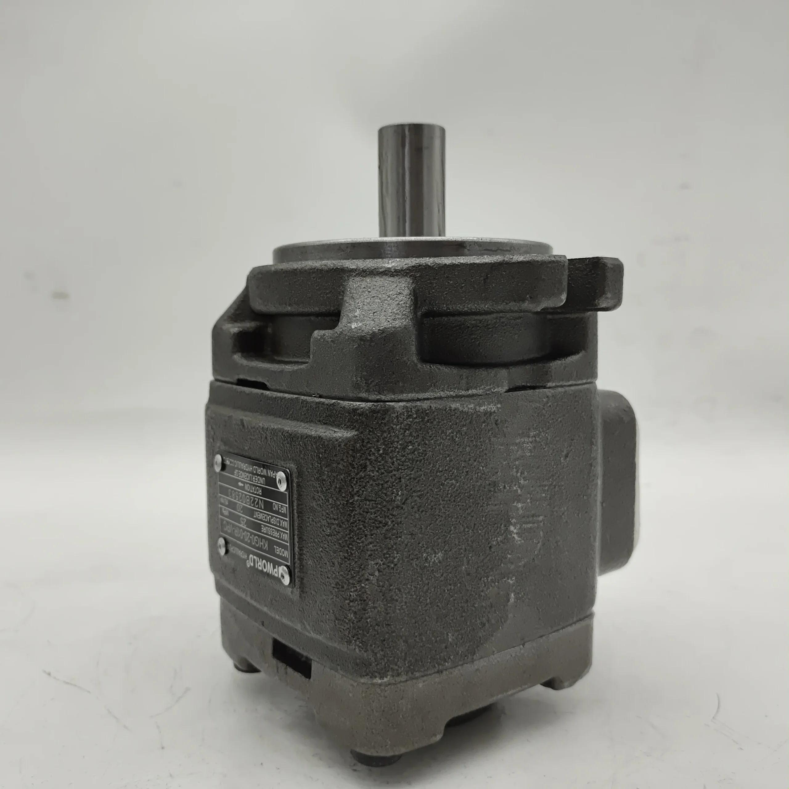
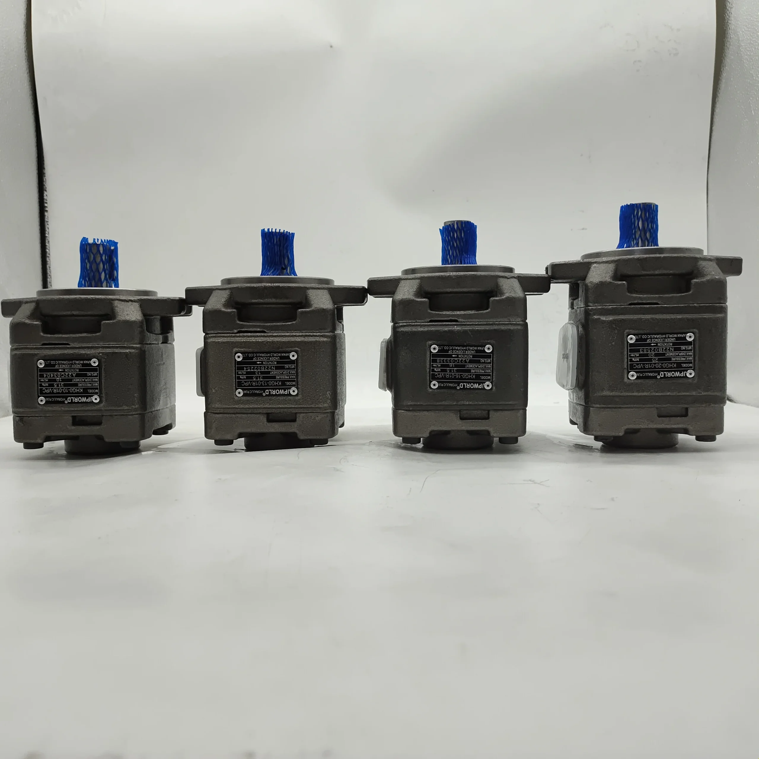
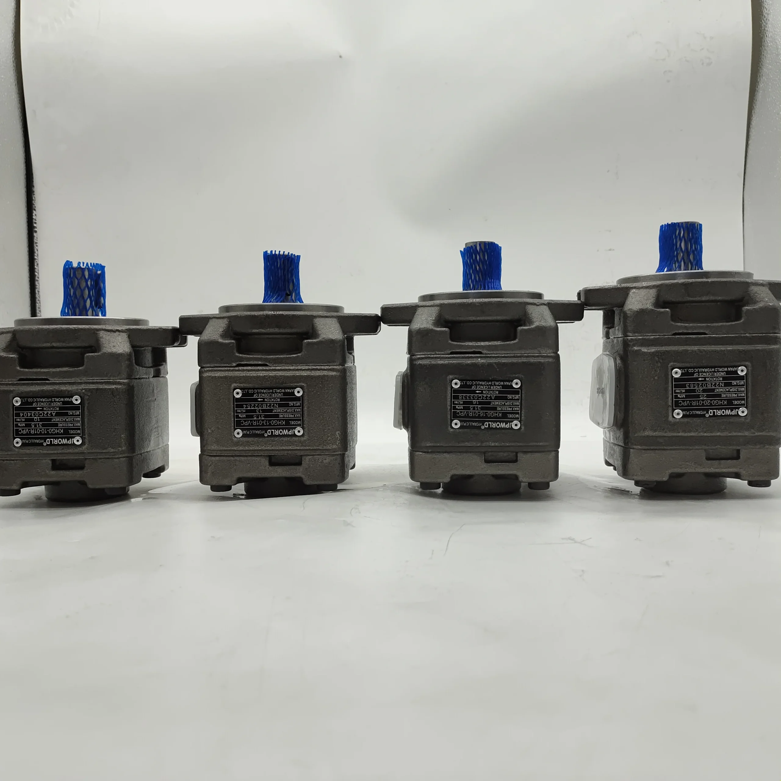
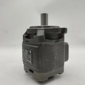
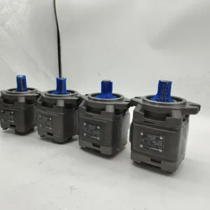
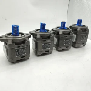
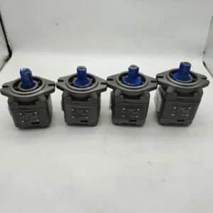
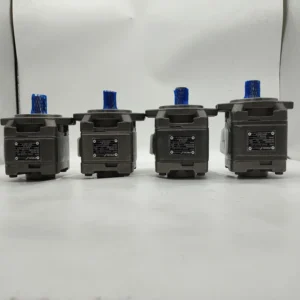

CPO CP1 CP2 HG0 HG1 HG2 HG0-16-01R-VPC HG1-32-01R-VPC-3 High Pressure Oil Hydraulic Pump
| Model Number | HG0-16-01R-VPC, HG1-32-01R-VPC-3 |
|---|
Product Description
CPO CP1 CP2 HG0 HG1 HG2 Internal Gear Pressure Pump HG0-16-01R-VPC HG1-32-01R-VPC-3 High Pressure Oil Hydraulic Pump
1. Basic performance parameters
– Pump body type: Single-stage external meshing fixed displacement gear pump, integrated pressure compensation distribution plate and micro relief valve, supports unidirectional rotary oil supply, suitable for small and medium-sized hydraulic power systems- Displacement and pressure parameters: Rated displacement 16 cc/rev (the “16” in the model corresponds to the displacement specification); The rated working pressure is 160 bar, the maximum allowable pressure is 200 bar (short-term ≤10 seconds), and the return oil back pressure is ≤2 bar
– Speed and flow parameters: Rated speed 3000 rpm, maximum speed 4000 rpm (short time ≤5 minutes), minimum stable speed 500 rpm; The output flow rate at the rated speed is approximately 48 L/min (16 cc/rev×3000 rpm÷1000)
– Efficiency parameters: Rated working condition volumetric efficiency ≥93%, total efficiency ≥88%, pressure loss at rated flow ≤5 bar
2. Structure and connection parameters
– Structural type: Cast iron one-piece formed pump body, surface anti-rust spray treatment; Nitrided alloy steel gears (hardness HRC62-65), tin bronze pressure self-compensating distribution plates, double-end mechanical seals
– Installation and connection specifications: Flange installation (compatible with ISO 3019-1 standard, model “01R” corresponds to right-rotating installation positioning); Oil port threads: Suction port G3/4, outlet port G3/4, control port G1/8; The output shaft is connected by a flat key (specification: 10×25). The overall weight is approximately 8 kg, and the external dimensions (length × width × height) ≈220×160×140 mm
– Protection grade: IP65, suitable for dusty and humid industrial and construction machinery environments
3. Medium and Environmental requirements
– Medium requirements: Compatible with L-HM 32/46/68 anti-wear hydraulic oil, allowable medium viscosity range 10-400 mm²/s, moisture content ≤0.02%, solid particle size ≤10 μm
– Environmental parameters: Operating environment temperature -25℃ to 90℃, relative humidity ≤95%; The cleanliness of the oil should reach ISO 4406 14/11 grade
– Filtration requirements: A filter screen of ≥80 mesh should be installed on the oil suction side, and the filtration accuracy on the oil return side should be ≤25 μm
Ii. Working Principle
This pump is a single-stage external meshing quantitative gear pump. Its core converts mechanical energy into hydraulic energy through the mechanism of “periodic change in gear meshing volume + pressure compensation seal” to achieve stable oil supply. The specific process is as follows:
1. Core mechanism of power transformation
The motor drives the driving gear to rotate, which in turn engages and rotates the driven gear in the opposite direction. A local vacuum is formed in the oil suction area where the two gears disengage. Under the action of atmospheric pressure, the hydraulic oil enters the pump chamber through the oil suction port and fills the gap between the gear tooth grooves. As the gears continue to rotate, the hydraulic oil in the tooth grooves is synchronously carried to the pressure oil zone on the meshing side. As the gears gradually mesh, the volume of the tooth grooves is continuously compressed, and the oil is mechanically squeezed to generate a stable pressure. The high-pressure oil under pressure is guided to the oil outlet through the pressure self-compensating distribution plate and discharged, then enters the hydraulic system to drive the actuating elements such as the cylinder and motor to act.
2. Pressure regulation and protection mechanism
The integrated micro relief valve is connected in parallel between the oil outlet and the oil suction port. When the system pressure rises to the rated value of 160 bar, the valve core of the relief valve begins to open for unloading. When the pressure exceeds the maximum allowable value of 200 bar, the relief valve is fully open to guide the excess oil back to the suction chamber, preventing overload damage to the pump body, pipelines and downstream components. The pressure self-compensating distribution plate automatically adheres to the end face of the gear under the action of high-pressure oil, and compensates for the wear clearance in real time, keeping the volumetric efficiency above 90% for a long time.
Iii. Product Features and Advantages
– High-efficiency and stable fuel supply: The pressure self-compensating distribution plate design ensures a volumetric efficiency of ≥93%, with a pressure fluctuation of ≤2% at the rated flow rate, and a 15% improvement in flow stability compared to conventional gear pumps. The 16cc /rev displacement is suitable for small and medium-sized systems, and the 48L /min flow rate can meet the requirements of most dual-actuator coordinated actions
– High wear resistance and long service life: Nitrided alloy steel gears combined with tin bronze distribution plates have a tooth surface wear of ≤ 0.1mm per 10,000 hours. The static leakage of the double-end mechanical seal is ≤1 mL/min, and the fault-free operation life under rated conditions is ≥ 12,000 hours, which is 30% longer than that of the ordinary gear pump of the same displacement
– Low noise and shock resistance: By using modified involute tooth profiles and high-precision gear meshing (clearance ≤ 0.03mm), the operating noise at 1 meter is ≤ 75dB, which is 5-8dB lower than that of conventional gear pumps. The cast iron pump body has an impact resistance strength of 10 J/cm², making it suitable for the bumpy working conditions of construction machinery
– Strong installation adaptability: Compatible with both flange and foot mounting methods, the oil port supports 360° rotation adjustment, adapting to different equipment layouts. The wide temperature range of -25℃ to 90℃ can adapt to high and low temperature working environments, and the rated pressure of 160 bar covers most medium and low pressure scenarios
Iv. Usage Functions and Purposes
1. Core usage functions
– Quantitative stable oil supply: Continuously provide hydraulic oil with stable pressure and flow for small and medium-sized hydraulic systems. As a power source for single or dual actuating elements, with a flow accuracy of ±2%, it is suitable for synchronous action control scenarios
– System overload protection: The built-in relief valve precisely controls the maximum pressure, replacing external pressure control components and increasing system integration by 20%. The pressure compensation mechanism prevents the flow rate from decaying with pressure and ensures the stable output of the actuator
– High-efficiency power transmission: The total efficiency is ≥88%, which can efficiently convert the mechanical energy of the motor into hydraulic energy. The power transmission loss is 10% lower than that of ordinary gear pumps, and energy consumption can be reduced by 15% in long-term operation
2. Main uses
As a core power component of small and medium-sized hydraulic systems, it is suitable for medium and low pressure, medium flow conditions, connects motors with actuating elements, and provides stable power for various industrial, engineering and agricultural machinery. It is the preferred power source for multi-actuating element coordinated action systems.
V. Applicable Machines and Scenarios
1. Adapt to the core machine
– Construction machinery: 3-5 ton loaders, small excavators, forklift steering systems, hydraulic rollers
– Industrial machinery: 100-300 ton presses, small injection molding machines, CNC lathe hydraulic tool turrets, fully automatic packaging machines
– Agricultural machinery: Large tractor suspension systems, header lifting mechanisms of combine harvesters, and peeling devices of corn harvesters
– Special equipment: Hydraulic lifting platforms, small ship deck winches, auxiliary action systems for small mine tunnel boring machines
2. Typical application scenarios
– Loader working scenario: As the hydraulic power source of a 3-ton loader, when the rated pressure is 160 bar and the flow rate is 48 L/min, the drive boom cylinder and the bucket cylinder act in coordination. The lifting time is ≤3 seconds and the unloading time is ≤2 seconds, meeting the efficiency requirements of the loading and unloading operation. IP65 protection is suitable for dusty environments on construction sites
– Press forming scenario: Equipped with a 200-ton small press, drive the slider cylinder downward to apply pressure. At a rated speed of 3000 rpm, the slider downward speed is 100 mm/s, and the pressure stability error is ≤1%, ensuring the forming accuracy of the stamped parts. The pressure compensation mechanism ensures that the flow rate decreases by no more than 3% after continuous operation for 8 hours
– Tractor suspension scenario: Drive the suspension mechanism of a large tractor to lift and lower. When the rated pressure is 140 bar, the suspension load is ≤3 tons, the lifting stroke is 500 mm, and the action response time is ≤0.5 seconds. It starts smoothly at -25℃ and is suitable for winter operations in northern farmlands
Six. Similar models
1. Different models of the same series displacement
-HG0-12-01R-VPC: Rated displacement 12 cc/rev, rated flow 36 L/min, rated pressure 160 bar, suitable for small single-actuator systems (such as small hydraulic lifting platforms, CNC tool turrets), with a volume 15% smaller than the original model and a weight of approximately 6.5 kg
-HG0-20-01R-VPC: Rated displacement 20 cc/rev, rated flow 60 L/min, maximum pressure 200 bar, suitable for large dual-actuator systems (such as 5-ton loaders, 400-ton presses), 25% stronger power than the original model, weight approximately 9.5 kg
2. Models with the same displacement but different functions
-HG0-16-01R-VPC-M: Manually adjustable relief valve model, suitable for simple systems with fixed pressure, featuring a more streamlined structure and a cost 18% lower than the original model
-HG0-16-01R-VPC-E: Electro-hydraulic proportional control model, supporting PLC remote adjustment of the relief valve pressure, control accuracy ±1 bar, suitable for automated production lines (such as multi-station assembly equipment), cost 40% higher than the original model
-HG0-16-01L-VPC: Left-rotating installation model, suitable for equipment with limited motor rotation direction. The oil outlet direction is opposite to the original model, while all other performances are exactly the same
3. Different models with different installation methods
-HG0-16-02R-VPC: Foot-mounted model, suitable for equipment with flange-free installation space. The installation base plate complies with ISO 7005-1 standard. Other performances are the same as the original model
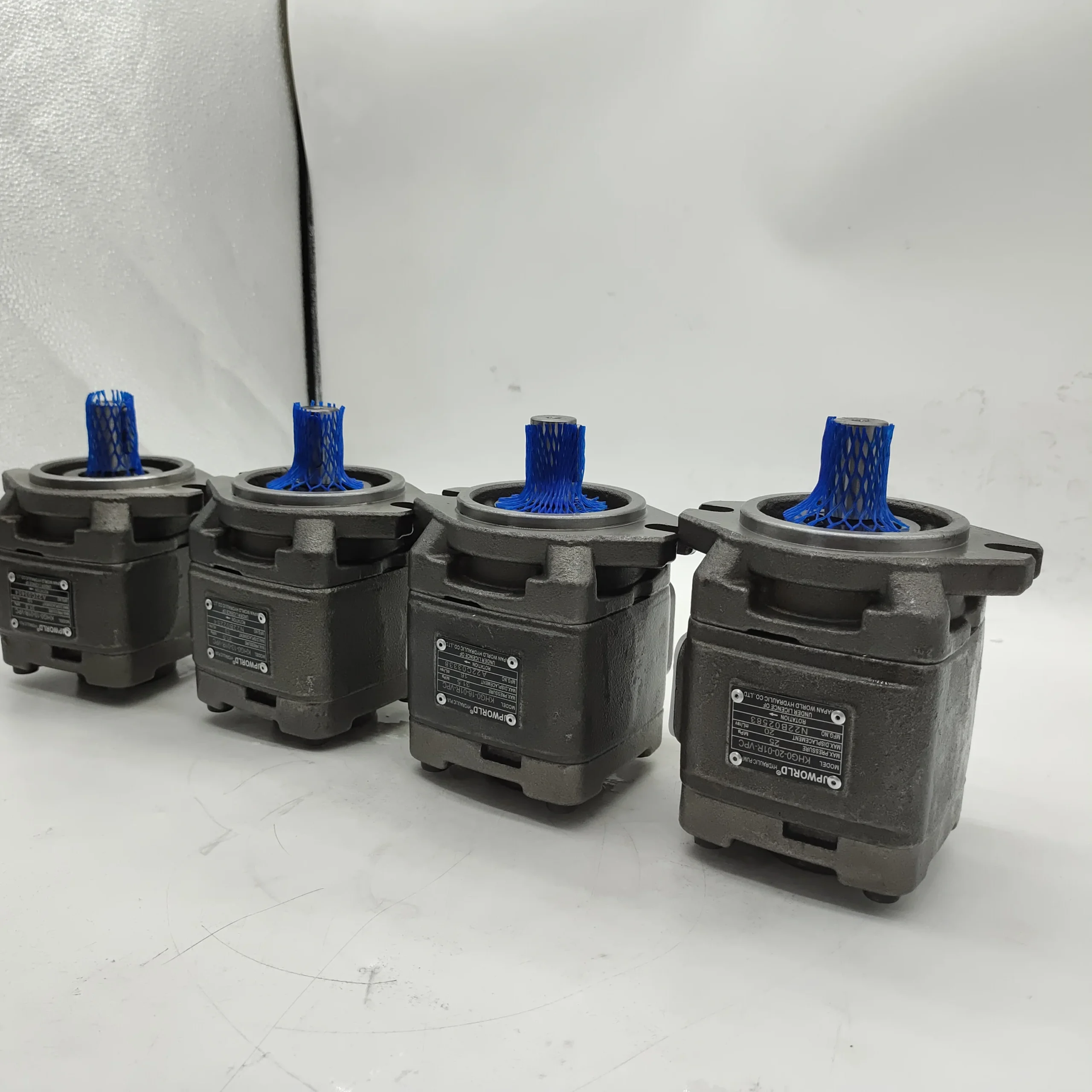
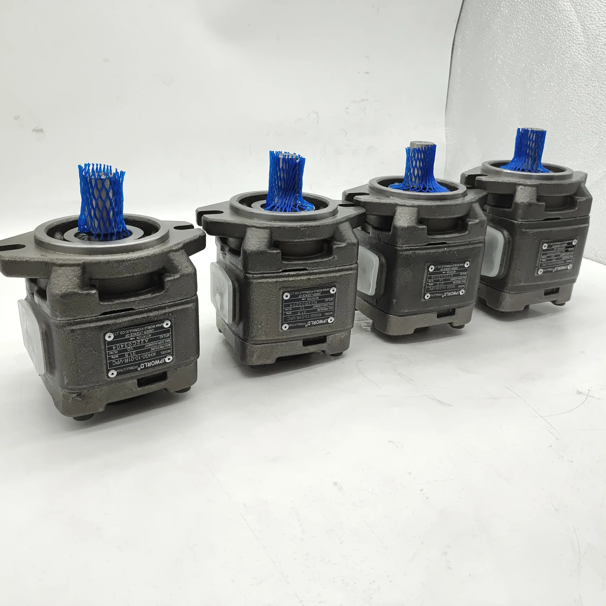
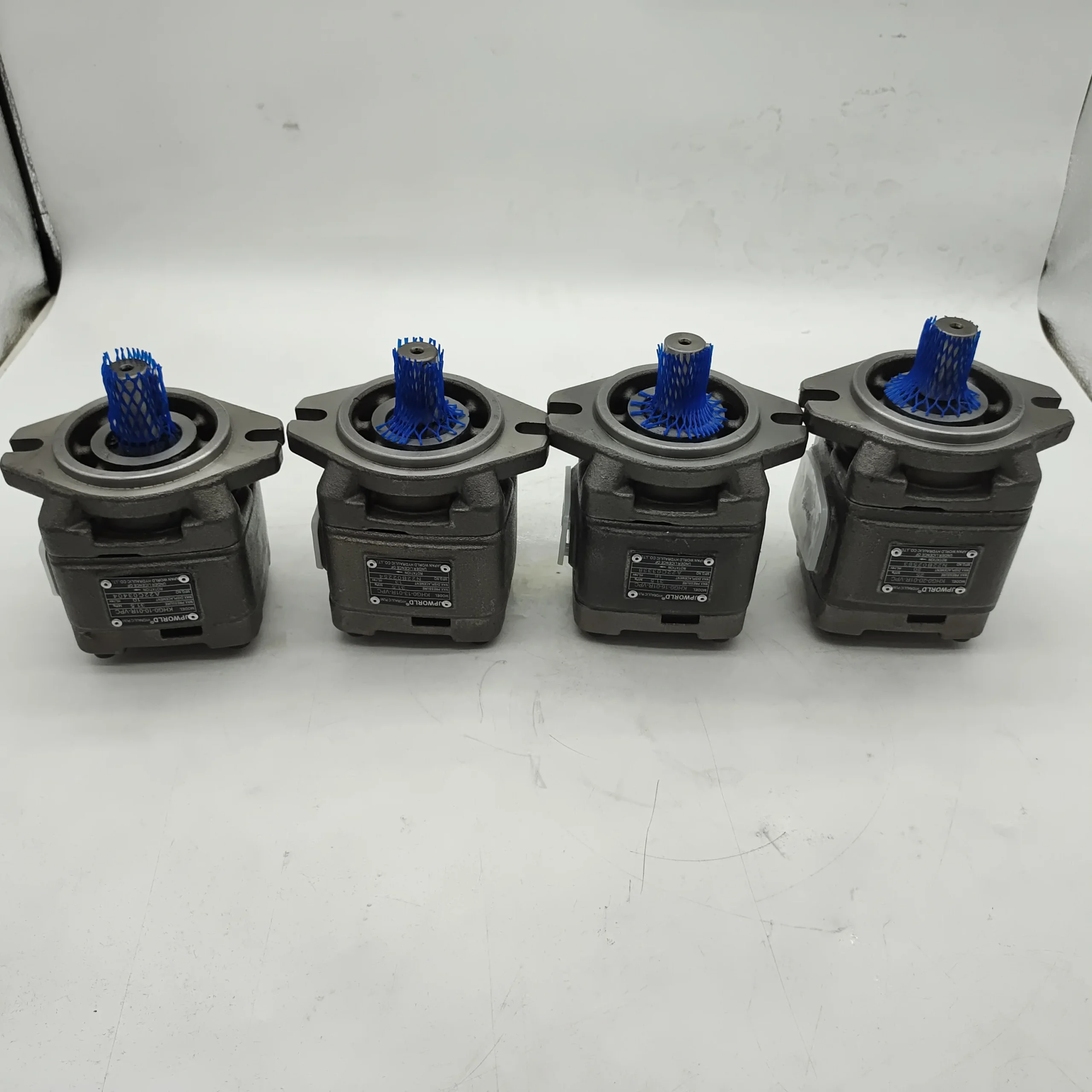
HG0-10-01R-VPC
HG0-13-01R-VPC
HG0-16-01R-VPC
HG0-20-01R-VPC
HG1-25-01R-VPC
HG1-32-01R-VPC
HG1-40-01R-VPC
HG1-50-01R-VPC
HG1-63-01R-VPC
HG2-80-01R-VPC
HG2-100-01R-VPC
HG2-125-01R-VPC
HG2-160-01R-VPC
Vii. Precautions for Use
Installation and commissioning
When installing, ensure that the coaxiality error between the pump shaft and the motor shaft is ≤ 0.1mm. Use an elastic coupling for connection. It is strictly prohibited to directly apply radial force (≥ 50N) to the pump shaft to avoid abnormal gear meshing
The oil suction pipeline should be short and thick (length ≤2 meters, diameter ≥25 mm), the distance between the oil suction port and the bottom of the oil tank should be ≥100 mm, and the filtration accuracy of the filter should be ≥80 mesh. The pipeline connection is fastened with double bolts, and the sealing gasket is made of oil-resistant nitrile rubber to prevent air leakage and cavitation
Before the first start-up, hydraulic oil (about 20 mL) should be injected into the pump cavity, and the pump should be manually turned by hand for 3 to 5 turns to ensure there is no jamming. When starting up, first open the oil suction valve and run it no-load at low pressure (50 bar) and low speed (1000 rpm) for 30 minutes. Gradually increase it to the rated parameters while checking for leakage and noise
For outdoor installation, a protective cover should be added to avoid direct sunlight and rain. Reserve a heat dissipation space of ≥ 150mm around the pump body. When the ambient temperature exceeds 40℃, forced ventilation is required. The oil temperature is best controlled at 40-60℃
2. Operation and Maintenance
During operation, the pump body temperature (normal ≤85℃, maximum not exceeding 95℃), outlet pressure and noise should be monitored daily. If the temperature rises sharply by more than 15℃, the pressure fluctuates by more than 5 bar or the noise exceeds 85 dB, stop the machine immediately for inspection. Focus on checking the oil contamination level (once every three months), gear wear or seal leakage
– Regular maintenance cycle: Replace the hydraulic oil and suction and return oil filters every 5,000 hours. Disassemble and inspect the gear wear every 10,000 hours (replace when the tooth surface wear is ≥ 0.15mm), and replace the mechanical seal and bearing. The pressure setting value of the relief valve should be calibrated with a pressure gauge every 2000 hours
It is strictly prohibited to run the machine without oil (idling for more than 5 seconds can easily cause damage to gears and bearings). Do not operate for a long time at the maximum speed (no more than 15 minutes at a time). When the system is overloaded, it should be shut down in time to prevent the relief valve from being unloaded for a long time, which may cause the oil temperature to exceed 95℃
3. Storage and Protection
When stored for a long time, all oil ports should be sealed with special plugs. Anti-rust oil (about 50 mL) should be injected into the pump cavity, and lithium-based grease should be applied to the keyway of the output shaft. Store in a dry warehouse with a temperature ranging from 0 to 45℃ and a humidity of no more than 60%. Avoid direct sunlight and heavy object compression. Manually turn the machine once every three months
Before putting the pump back into use after being idle for more than 12 months, thoroughly clean the pump cavity and pipelines, replace all seals and hydraulic oil, and recalibrate the pressure of the relief valve. Run the low-speed no-load test for 20 minutes to check the pressure stability and leakage rate (≤1 mL/min is normal). Only after meeting the standards can it be connected to the system.
Company Profile


Professional Manufacturer