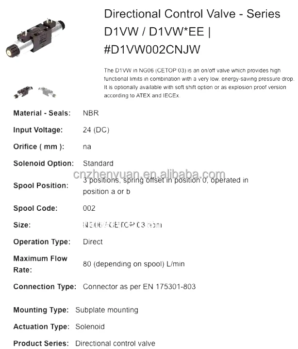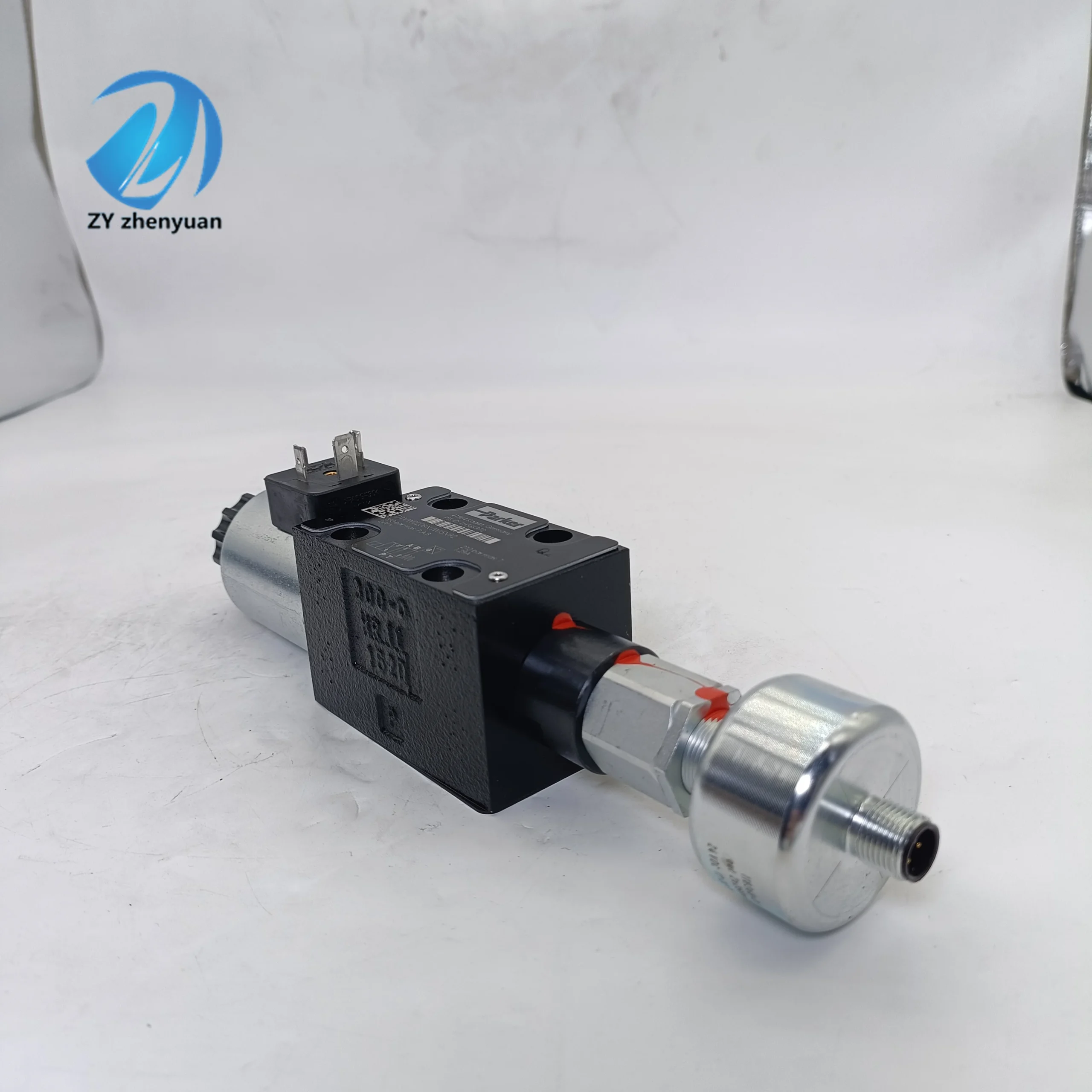
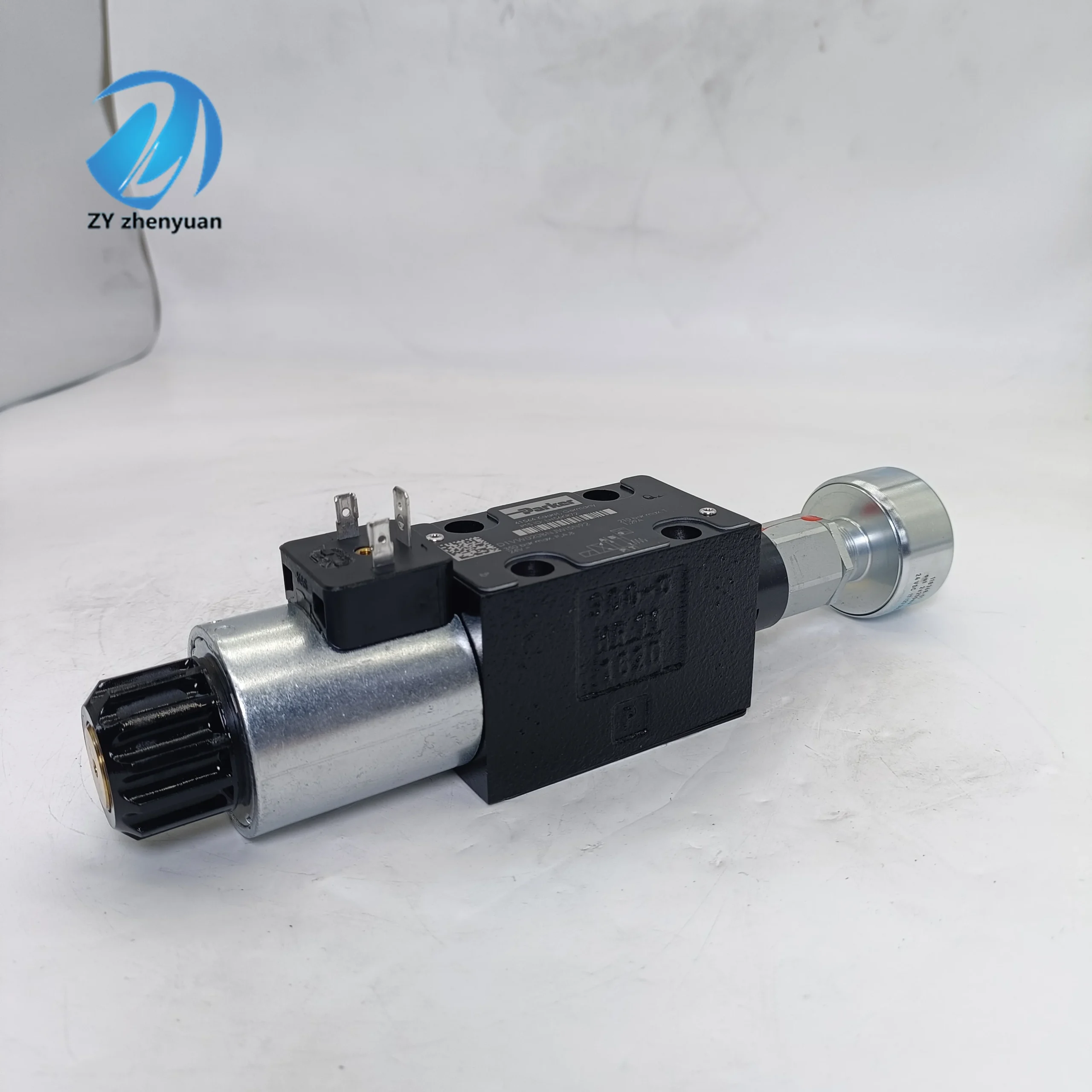
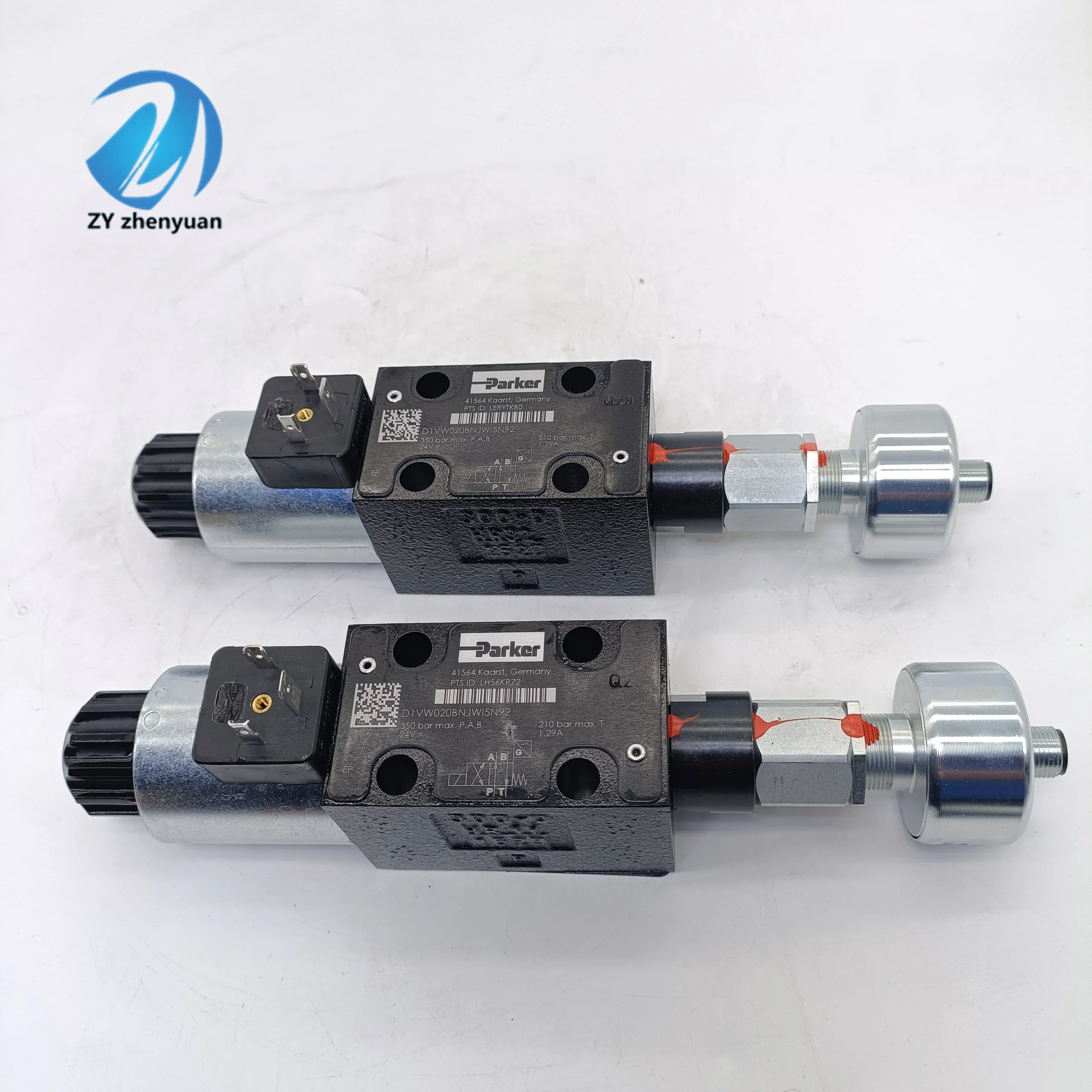


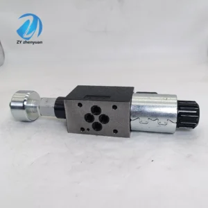
D1VW004CNJW91 Hydraulic Solenoid Valve D3W004CNJW42 Directional Control Valve Hydraulic D1VW008CNJW D1 D3 D1V D1VW D3W
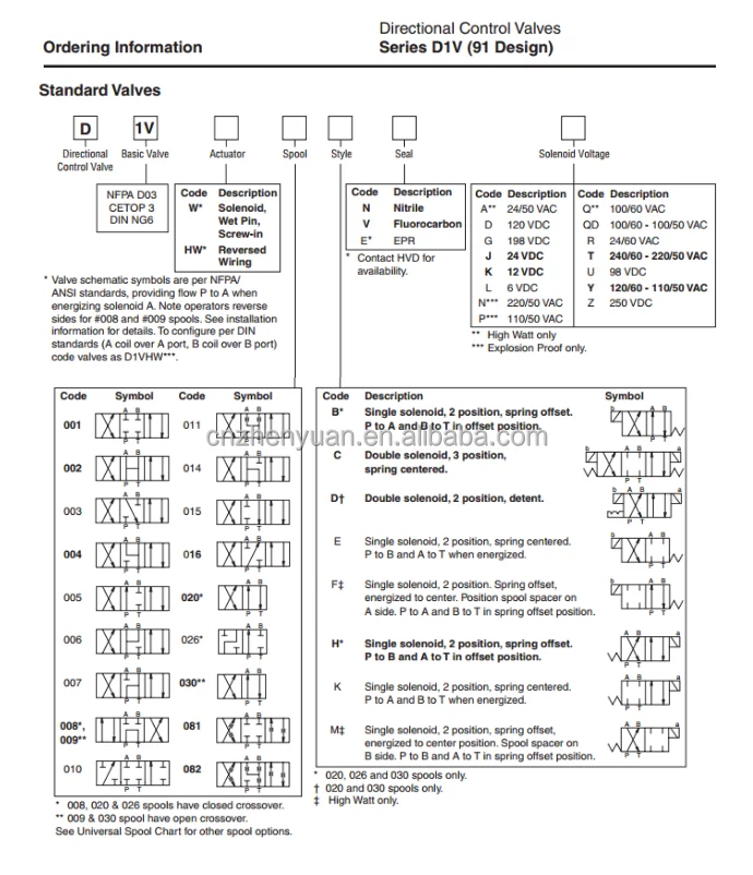
Valve type: Three-position four-way slide valve type electromagnetic directional control valve; It has 3 working positions and 4 oil ports, and reversing is achieved through electronic control
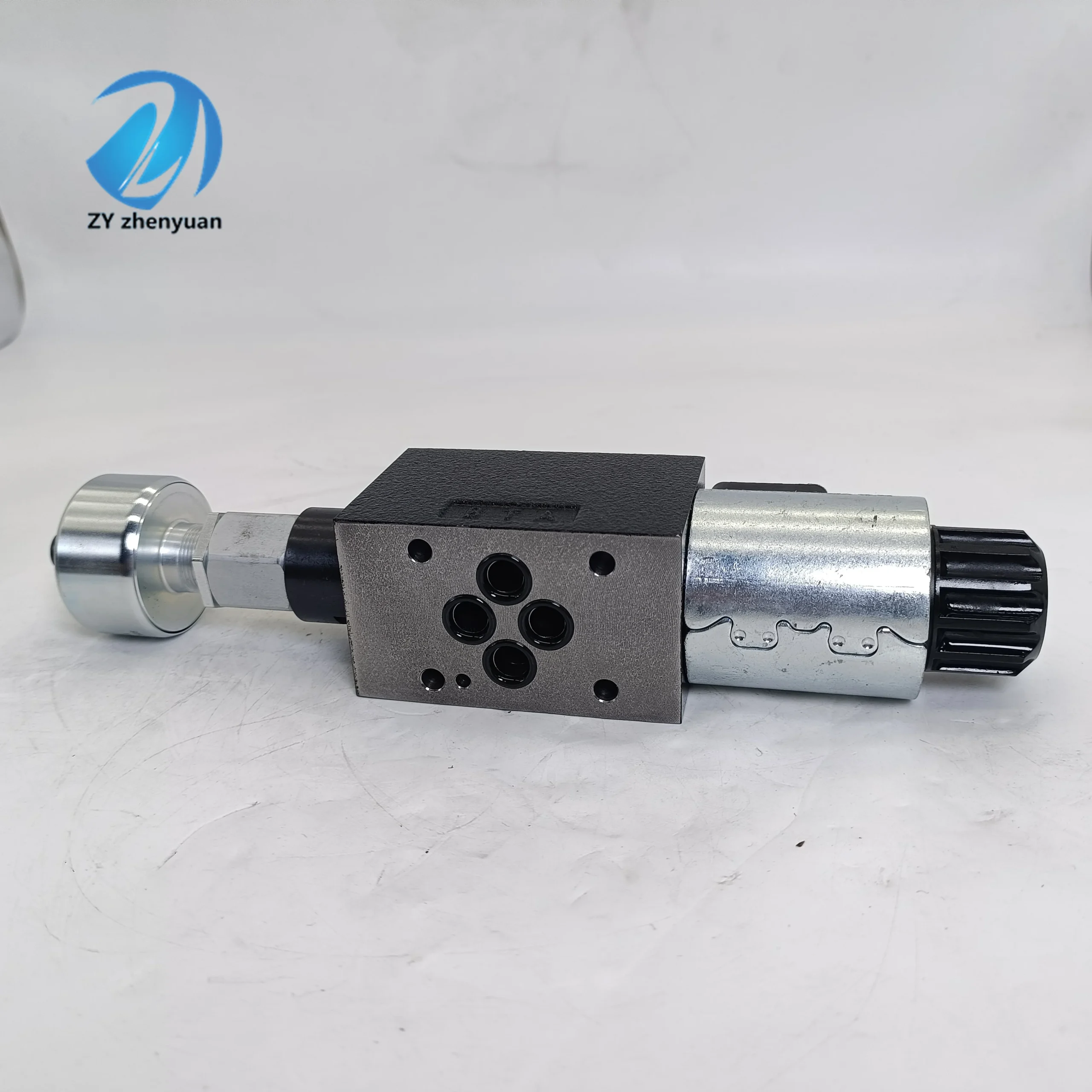
Installation specification: NG06 (CETOP 03 / NFPA D03); It adopts a standard plate installation method and is compatible with a universal installation base plate
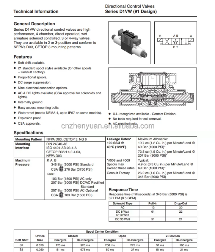
Working pressure range: P, A, B ports: 350 bar; Port T: 210 bar for DC operation, 105 bar for AC operation; The pressure resistance of the oil inlet and working oil port is higher, while the pressure resistance of the return oil port varies depending on the type of power supply
Flow capacity: Maximum 80 L/min; The flow performance matches the specific model of the valve core, and this value can be achieved under standard configuration
Medium requirements: Hydraulic oil (conforming to DIN 51524/51525 standard); It is necessary to ensure the cleanliness of the medium to prevent impurities from affecting the operation of the valve core
Temperature range: Medium temperature -25 ℃ to +70℃, ambient temperature -25 ℃ to +60℃; Exceeding the range can easily lead to aging of the sealing parts and damage to the coils
Power supply parameters: Standard DC 24V, AC version available as an option; Voltage fluctuations should be controlled within ±10% of the rated value to ensure stable operation
Sealing material: Standard NBR (nitrile rubber), and special materials such as VITON are optional; NBR is compatible with conventional hydraulic oil. For special media, the corresponding seals need to be replaced
Connection method: EN 175301-803 standard connector (DIN 43650 type); The plug-in connection features excellent anti-loosening and sealing performance
Valve core form: Standard C type, multiple specifications available; Different valve cores are suitable for different circuit requirements such as unloading and pressure holding
Action performance: Response time 10-30ms, maximum switching frequency 15,000 times per hour; Rapid response meets the demands of high-frequency control scenarios
Weight: Approximately 2.5kg; It does not include installation accessories and is suitable for the requirements of lightweight equipmentIi. Working Principle
This solenoid valve operates based on the principle of electromagnetic induction drive and spool valve reversing. The core changes the position of the valve core through the on-off of the electromagnet, achieving the switching of the hydraulic oil flow path. The specific process is as follows:
Median state (power-off) : The valve core is centered under the action of the reset springs at both ends, the oil inlet (P port) is closed, the working oil ports (A and B ports) are connected to the return oil port (T port), the system is unloaded, and the actuator stops operating
Left position (left coil energized) : The left electromagnet is energized to generate A magnetic field, attracting the valve core to overcome the force of the right spring and move to the right. Port P is connected to port A, and Port B is connected to port T. Hydraulic oil enters the actuator through port A to complete the action (such as the cylinder extending).
Right position state (right coil energized) : The right electromagnet is energized to generate A magnetic field, attracting the valve core to overcome the force of the left spring and move left. Port P is connected to port B, and Port A is connected to port T. Hydraulic oil enters the actuator through port B to complete the reverse action (such as the cylinder retract).
This valve is directly driven by a wet electromagnet, without the need for pilot pressure, and can be stably reversed under zero pressure difference. The electromagnet is designed to be isolated from the medium to avoid the risk of dynamic seal leakage.
Iii. Product Features and Advantages
1. Core features
High-efficiency flow channel design: Internal flow channel optimization enables a large flow rate of 80L/min even when the pressure drop is ≤3bar, enhancing the system’s energy efficiency
Multi-valve core compatibility: It offers various valve core specifications such as C, D, and E, enabling functions like unloading, pressure holding, and bidirectional flow, and is suitable for complex hydraulic circuits
Reliable sealing structure: The integrated sealing design, combined with high-quality materials, has an extremely low risk of external leakage and nearly zero internal leakage, enhancing the system’s sealing performance
Compact and lightweight: NG06 specification, small in size and weighing only 2.5kg, saves installation space and meets the requirements of equipment miniaturization
Wide operating condition adaptability: With a wide temperature range of -25℃ to +70℃ and a high-pressure resistance capacity of 350bar, it is suitable for harsh industrial environments
2. Highlight the advantages
High reliability: The wet electromagnet has a protection grade of IP65 and strong anti-pollution ability. Spring reset ensures a return to the neutral position after power failure, with high safety redundancy and a service life of up to one million cycles
Convenient maintenance: The coil is modularly designed and can be replaced online without disassembling the oil pipe and valve body. The valve core is easy to disassemble, facilitating cleaning and maintenance
Low operating loss: The high-efficiency flow channel reduces pressure loss, and the low-power design of the electromagnet results in low long-term operating costs
Smooth reversing performance: Damping holes can be optionally equipped to achieve gentle switching. The reversing time is adjustable from 50 to 200ms, reducing the hydraulic shock protection system
Iv. Usage Functions and Purposes
1. Core usage functions
Directional control: Controls the flow direction of the hydraulic oil to achieve the switching of the actions of the actuating elements such as the extension and retraction of the cylinder and the forward and reverse rotation of the motor
System unloading: In the median state, port P is closed and ports A/B are open to Port T, achieving system unloading in non-working conditions and reducing energy consumption and heat generation
Pressure protection: By coordinating the valve core with the return oil port, pressure is released when the system is overloaded, preventing damage to pipelines and components
Sequential control: When used in conjunction with multi-valve groups, it controls the action sequence of multiple actuating elements through the on-off timing sequence to achieve an automated process
2. Main uses
As a core control component of the hydraulic system, it precisely controls the flow direction of hydraulic oil through electrical signals, connects the electrical control system with the hydraulic execution system, and drives the action control of mechanical devices. It is a key control node of the hydraulic system.
V. Applicable Machines and Scenarios
Industrial machinery: injection molding machines, presses, CNC lathes, rubber vulcanizing machines; It is suitable for high-frequency and precise reversing scenarios such as mold opening and closing, slider lifting and lowering, and tool rest feed
Construction machinery: excavators, loaders, cranes, shield machines; It is suitable for heavy-duty actions such as the extension and retraction of hydraulic arms and the flipping of buckets, and can withstand high pressure and harsh environments
Agricultural machinery: tractors, combine harvesters, seeders; Control the lifting of agricultural machinery and the start and stop of harvesting devices to adapt to the high and low temperatures and dusty environments in the fields
Metallurgical equipment: continuous casting machines, steel rolling mills, blast furnace ironmaking equipment; It is suitable for action control in high-temperature working conditions such as roller conveyor drive and billet clamping
Marine machinery: Deck winches, steering gears, ship cargo cranes; Adapted to the high-humidity and salt spray environment at sea, it controls key actions such as lifting and steering
Wind power equipment: Pitch system and yaw system of wind turbine units; It is used for blade Angle adjustment and nacelle steering, and requires high reliability and long service life
Automated production lines: robot arms, material handling equipment, assembly lines; Achieve precise positioning and action switching, in conjunction with PLC automatic control
Six. Similar models
D1VW001CNKW91: It has a lower flow capacity (up to 60L/min) and a smaller volume. Compatible with small hydraulic systems and light-load equipment (such as small machine tools and medical devices)
D1VW020BNHW91: Higher flow capacity (up to 120L/min), consistent pressure resistance; Compatible with large-scale hydraulic systems and high-flow equipment (such as large injection molding machines and shield machines)
D1VW004KNJW91: Valve core type K, with pressure-holding function. At the neutral position, ports P, A, B, and T are all closed. Adapt to scenarios where the position of the actuator needs to be maintained (such as crane boom locking, press slider positioning)
D1VW004ENJW91: Valve core type E. In the middle position, port P is connected to ports A and B, while port T is closed (or customized as required). Suitable for multi-actuator synchronous oil supply scenarios (such as multi-cylinder synchronous action systems)
D1VW020HNJW91
D1VW001CNYGF561M91
D1VW004CNYC561M82
D1VW020HNYCF5682
D1VW001CNJW91
D1VW004CNJW91
D1VW216HNJW91
D1VW020HNJW91
D1VW004CNJW91
D1VW001CNJW91
D1VW004CNJW91
D1VW216HNJW91
D1VW020HNJW91
D1VW004CNJW91
D1VW020BNTW
D1VW004CNJPM4
D1VW020DNJW
D1VW004CNJW3
D1VW020BNJW3
D1VW001CNJW
D1VW004CNJW91
D1VW20BVYCF75
D1VW20HNYW+5001573
D1VW20HNJW
D1VW20HNJW
D1VW020BNJW
D1VW020BNJW91
D1VW004CNJW
D1VW004CNJW91
D1VW20HNJEE75
D1VW020HNJW
D1VW078KNJW
D1VW076KNJW
D1VW020BNJW
D1VW008CNJW
D1VW020BNJW
D1VW004CNJW
D1VW006CNJW
D1VW020DNJWS391
D1VW004CNJW91
D1VW020BNJW91
D1VW020DNJWS391
D1VW008CNJW91
D1VW020BNJW
D1VW020BNJW
D1VW005CNJW
D1VW004CNJW
D1VW020DNJW
D1VW020DNJW
D1VW004CVJW
D1VW004CVJW91
D1VW004CNJW91
D1VW020BNJW91
D1VW004CNJW91
D1VW010CNJW91
D1VW001CNJW91
D1VW008CNJW91
D1VW034CNJW91
D1VW002CNJW91
D1VW004CNJW91
D1VW002CNJW91
D1VW020BNJW91
D1VW006CNJW91
D1VW020BVZPG
D1VW002CNJW
D1VW020BNJW
D1VW006CNJW
D1VW020BNJW91
D1VW004CNJW91
D1VW008CNJW91
D1VW001CNJW91
D1VW010CNJW91
D1VW020BNJW91
D1VW008CNJW91
D1VW020HNJEE92
D1VW001KNJEE92
D1VW004CNTW91
D1VW4CJJ53
D1VW006KNJW91
D1VW216HNJW91
D1VW020HNJW91
D1VW001KNJWI4N4D
D1VW002CNGW
D1VW002EVJW
D1VW002KNJWS2
D1VW004CNGWS2
D1VW004CNJW4D
D1VW004CNJWL
D1VW004CVJW
D1VW004CVJWL
D1VW016CNJW
D1VW020BNJDJ5
D1VW020BNJWI5N
D1VW020BNJWL
D1VW020BNJWT
D1VW020BNJWTI5N
D1VW020DNJDJ5
D1VW020HNJGI4N4D
D1VW020HNJWI4N
D1VW020HVJW
D1VW026BNJW
D1VW078KNJGI4N4D
D1VW101BNJW
D1VW101BNJWS2
D1VW102ENJDJS25
D1VW002CNJG
D1VW002CNJG91
D1VW004CNJWS2
D1VW004CNJWS291
D1VW004CNGW
D1VW004CNGW91
D1VW001CNGW
D1VW001CNGW91
D1VW020HNJW91
D1VW020HNJW91
D1VW009CNJW
D1VW020BNJW
D1VW004CNJPM4
D1VW020HNJW
D1VW020HNJW91
D1VW004CNJW
D1VW020BVJW91
D1VW006CNJW91
D1VW020HNYW
D1VW020HNYW91
D1VW20HNJW
D1VW2CNJW
D1VW020BNJW
D1VW004CNJW
D1VW020DNJWS391
D1VW020HNJW91
D1VW020HNJW92
D1VW020HNJW91
D1VW020HNJW91
D1VW020HNJW91
D1VW004CVJW
D1VW004CVJW91
D1VW034CNJW91
D1VW002CNJW91 24V
D1VW002CNJW91
D1VW006CNJW91
D1VW020BVZPG
D1VW002CNJW
D1VW020BNJW
D1VW006CNJW
D1VW020BNJW91
D1VW004CNJW91
D1VW008CNJW91
D1VW001CNJW91
D1VW010CNJW91
D1VW020BNJW91
D1VW008CNJW91
D1VW001CNJW
D1VW004CNJW
D1VW006KNJWVii. Precautions for Use
Installation requirements: Horizontal installation is preferred with the coil facing upwards to prevent oil from entering. Reserve at least 150mm of maintenance and heat dissipation space around. The flatness of the installation base plate should be ≤0.05mm to prevent leakage. It is prohibited to use the coil as the fulcrum of the wrench
Medium management: The medium must be filtered through a filter screen of ≥60 mesh, with a contamination level of ≤NAS grade 8. Viscosity control: 15 to 40cSt. Excessively high viscosity will affect the response. Check the oil cleanliness every 500 hours and replace the filter in time
Electrical connection: Voltage fluctuation is controlled within ±10% of the rated value. Ensure good grounding to prevent leakage. The cross-sectional area of the cable is ≥1.5mm² and the length is ≤50m. The plug is firmly connected to prevent loosening due to vibration
Operation and maintenance: Manually test the position of the valve core before startup. Avoid frequent power on and off (with an interval of less than 1 second) to prevent overheating of the defense circle. Use the “point operation” mode for exhaust during the first run. Regularly inspect the seals and replace them in time if they age
Storage protection: For long-term storage, use a dedicated plug to seal the oil port, fill the cavity with anti-rust oil, and apply lithium-based grease to the shaft. Store in a dry environment with a temperature ranging from 0 to 45℃ and a humidity of no more than 60%. Manually turn the wheel once every three months. If it has been idle for more than 12 months, the sealing parts need to be replaced and a no-load test run should be conducted before it is put into use