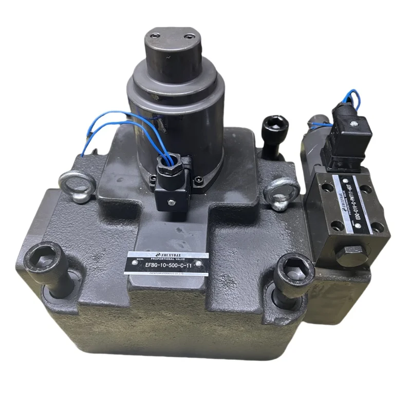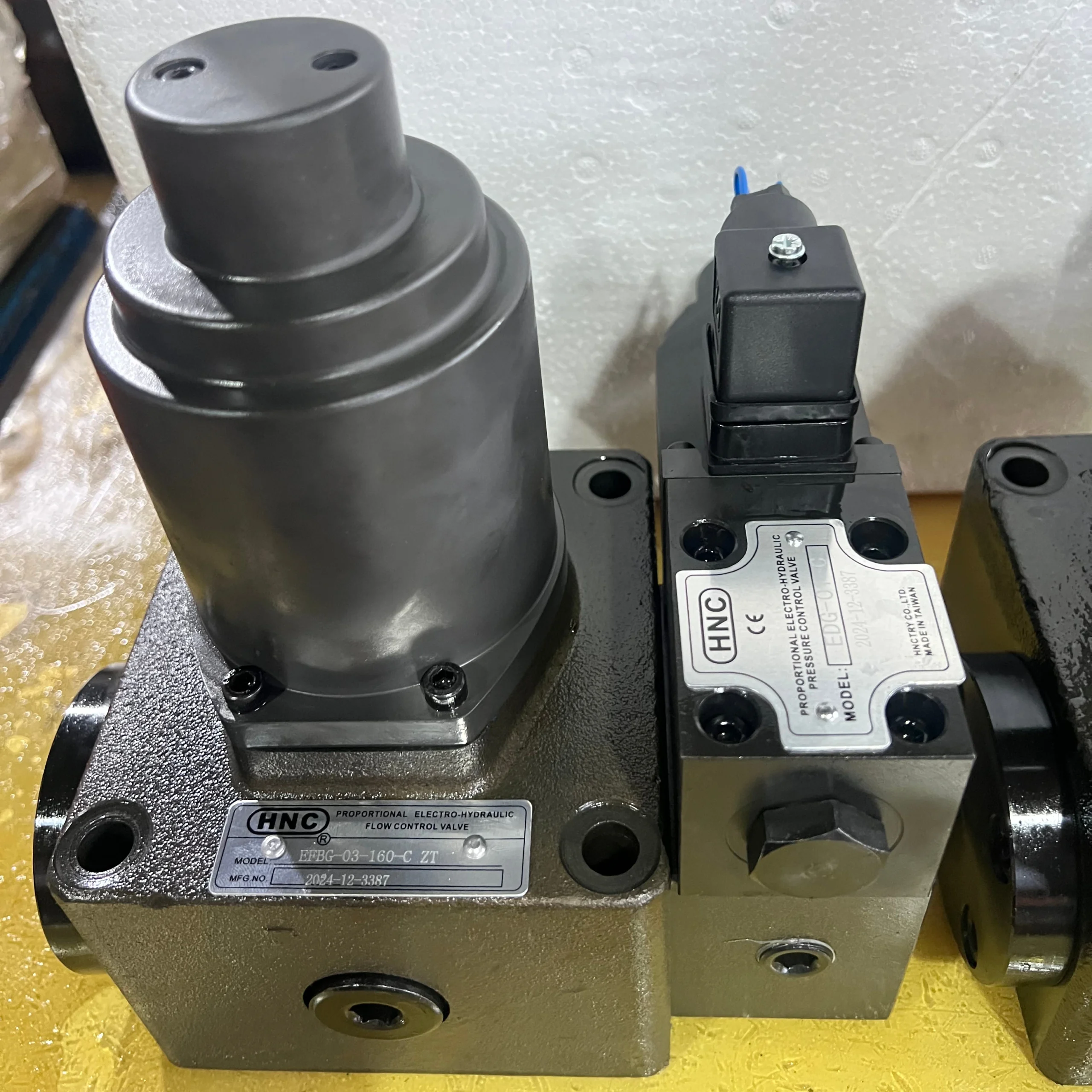
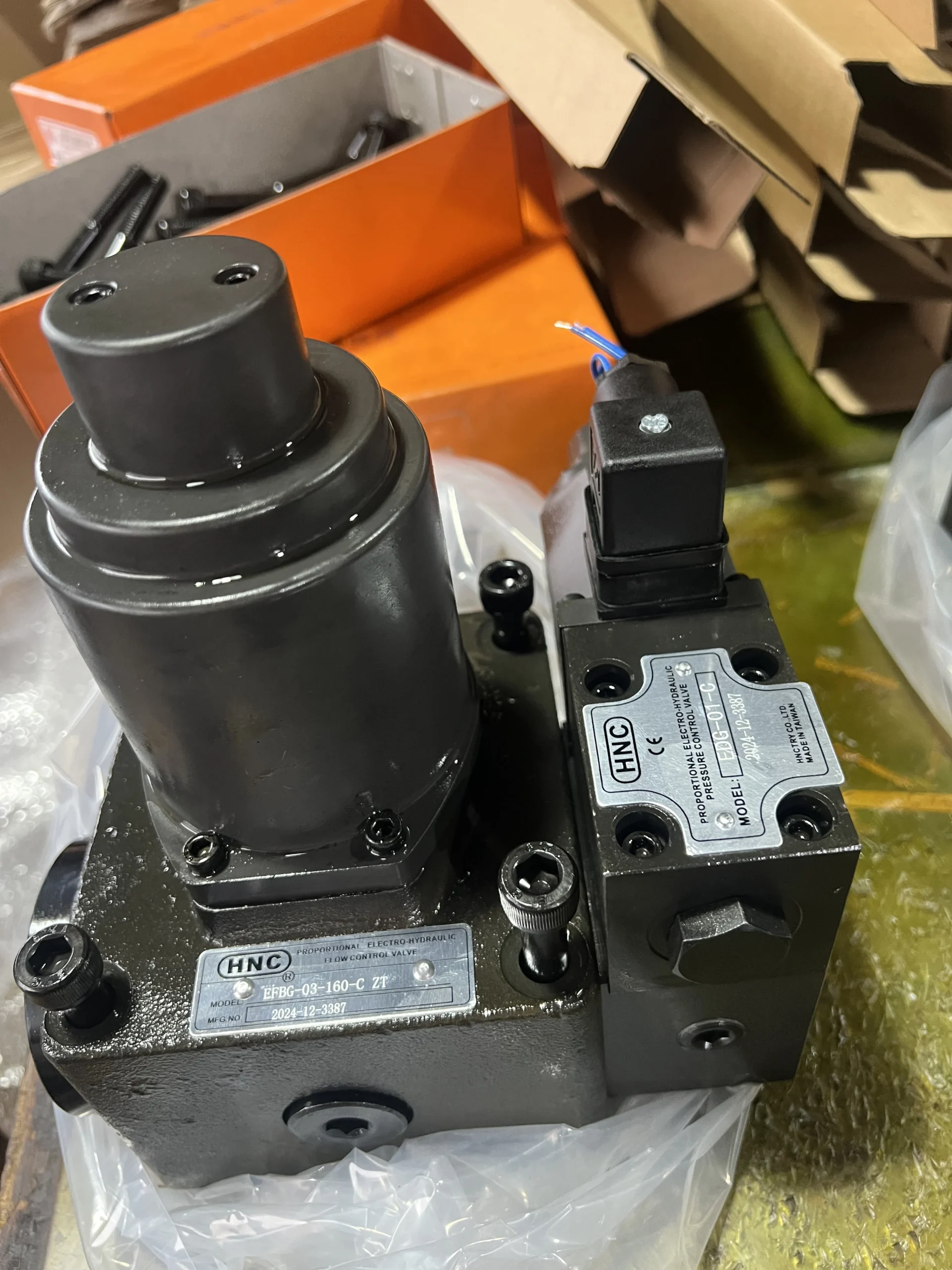
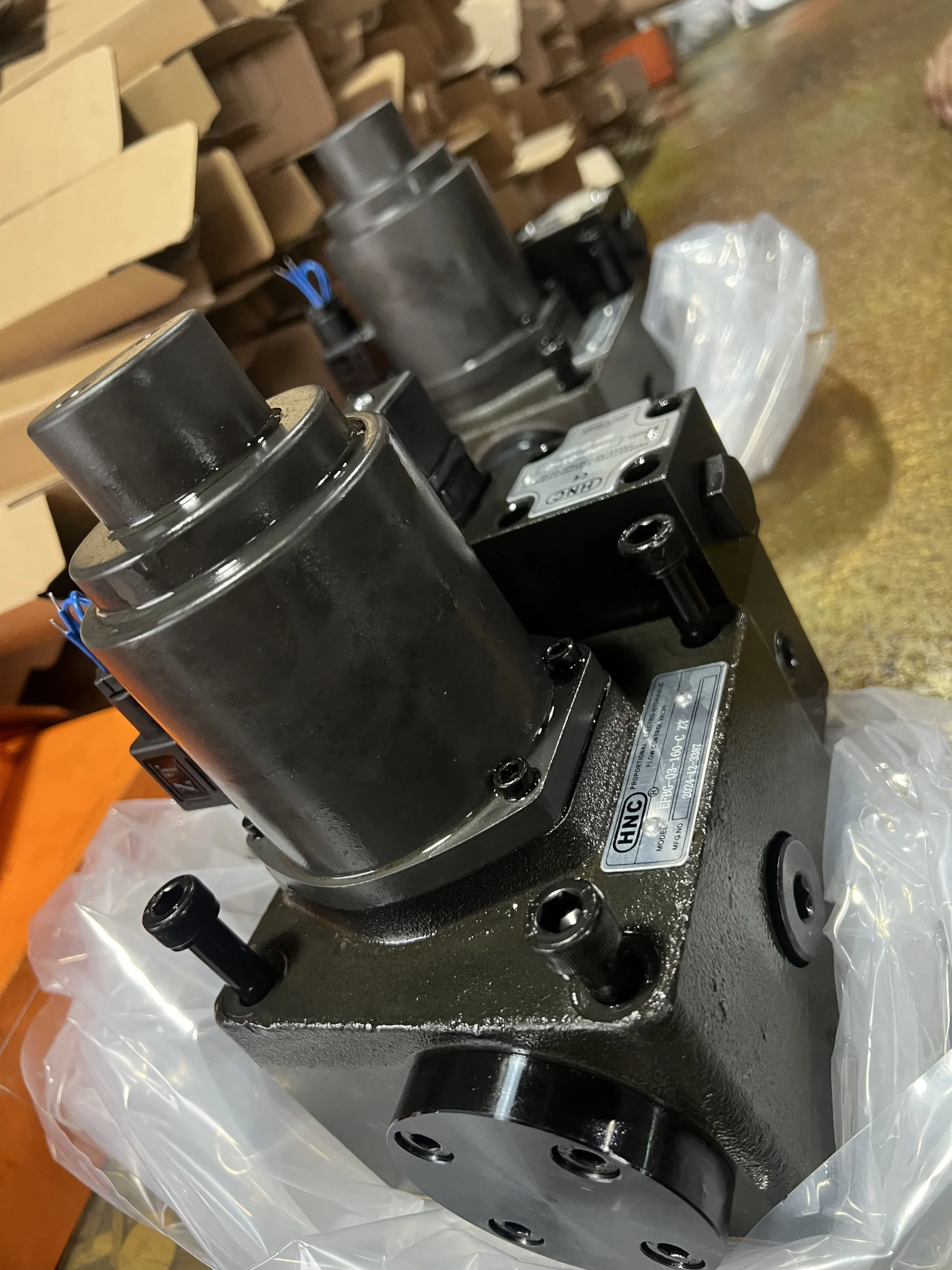
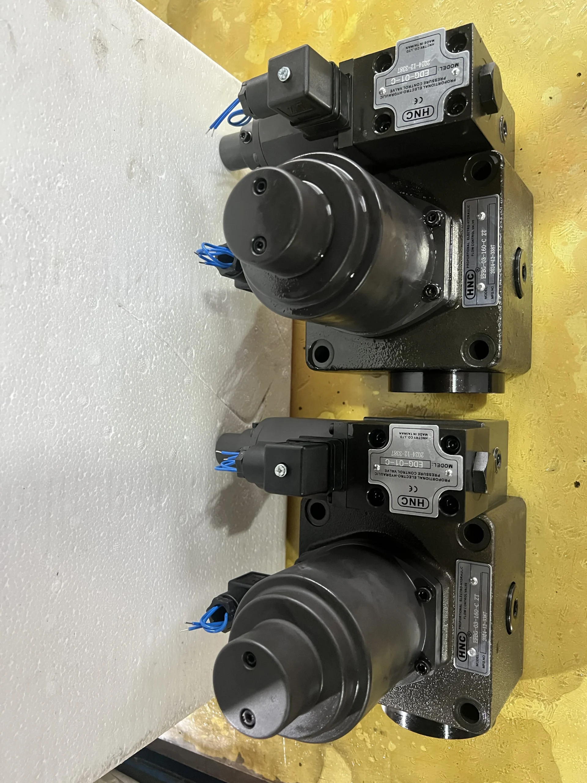
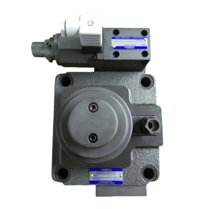
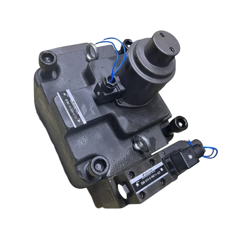


EFBG-03-125-C-20T233L Proportional Electro-hydraulic Control Valve EFBG EDG EFBG-03 EFBG-06 EFBG-10 Proportional Hydraulic Valve
Core performance parameters
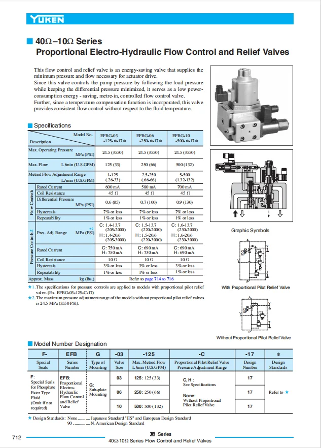
– Valve type: Electro-hydraulic proportional overflow speed control valve, integrating overflow and speed control functions, three-way structure (P for oil inlet, A for working oil port, T for oil return), supporting stepless flow regulation and system pressure limiting, suitable for small and medium-sized high-pressure hydraulic systems.
– Pressure and flow parameters: Rated working pressure 21 MPa (P port), proportional overflow pressure adjustment range 0.5-21 MPa; Rated flow rate: 125 L/min (at a pressure difference of 1 MPa), flow regulation range: 5-125 L/min. Control accuracy: Flow repeatability accuracy ≤1.5%, pressure regulation accuracy ≤0.3 MPa.
– Control and response parameters: Control voltage 24V DC, command signal compatible with 0-10V voltage or 4-20mA current; The flow response time is ≤100 ms, and the pressure response time is ≤80 ms. Built-in proportional electromagnet with temperature compensation function.
– Operating characteristics: Working oil temperature -20℃ to 75℃; The maximum pressure loss during continuous operation is ≤1.0 MPa. With a protection grade of IP65, it is suitable for scenarios such as industrial workshops and hydraulic stations of construction machinery.
2. Structure and connection parameters
– Structural type: Integrated cast iron valve body, precision slide valve, proportional electromagnet, relief valve assembly and flow feedback hole; It adopts high-pressure resistant fluororubber seals. The valve core is hardened (hardness HRC58-62), and the inner cavity of the valve body is polished to reduce pressure loss.
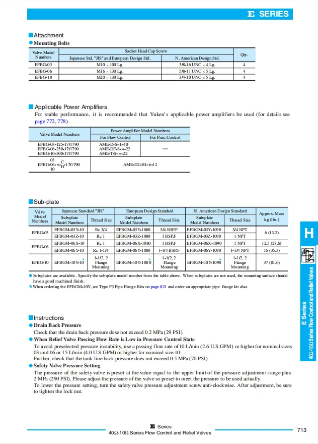
– Connection specification: The oil port connection is threaded (all P/A/T ports are G1/2″). The electrical connection is an M16×1.5 waterproof plug. The installation method is plate mounting (conforming to ISO 7368 standard), and the weight of the valve body is approximately 3.8 kg.
3. Medium and Environmental requirements
– Medium requirements: L-HM 46 anti-wear hydraulic oil is suitable for normal temperature, and L-HM 32 is selected for low temperature (below -15℃). The allowable medium viscosity is 15-350 mm²/s, and the moisture content is ≤0.03%. It is strictly prohibited to use media containing solid particles (particle size > 10 μm) or corrosive media.
– Cleanliness standard: The oil cleanliness should reach ISO 4406 16/13 grade. A 10 μm fine filter should be placed in front of the oil inlet. The filter element should be replaced immediately when the pressure difference of the filter is greater than 0.1 MPa.
– Environmental parameters: Operating environment temperature -20℃ to 75℃, relative humidity ≤95% (short-term condensation is allowed); With a protection grade of IP65, it is suitable for industrial damp workshops and hydraulic systems of small and medium-sized construction machinery.Ii. Working Principle
This valve is an electro-hydraulic proportional overflow speed-regulating compound valve. Its core achieves precise flow regulation and stable pressure control in the hydraulic system through the collaborative mechanism of “proportional electromagnet pressure control – overflow valve pressure stabilization – speed-regulating valve flow control”. The specific process is as follows:
1. Median initial state
When the proportional electromagnet is not energized, the relief valve is in a low-pressure setting state under the action of the spring, and the valve core of the speed control valve is in the closed position. At this point, the oil from port P is directly returned to Port T through the relief valve, and there is no pressure oil output from port A. The actuator remains stationary, and the system is in A low-pressure unloading state.
2. Core process of speed regulation control
When an electrical signal is input to the proportional electromagnet, the electromagnet generates an electromagnetic force proportional to the signal strength, which drives the valve core of the relief valve to move and increases the set pressure of the relief valve. As the system pressure rises, the pressure oil pushes the valve core of the speed control valve to open. The opening degree is proportional to the pressure change, thereby controlling the flow output from port A to the actuator. When the intensity of the electrical signal increases, the set pressure of the relief valve rises, the opening degree of the speed control valve increases, the flow rate at port A increases proportionally, and the speed of the actuator increases. When the electrical signal weakens, the flow rate decreases accordingly.
3. Pressure protection and feedback regulation
When the system pressure exceeds the set pressure of the relief valve, the relief valve automatically opens to unload, ensuring that the system pressure remains stable at the set value. The built-in flow feedback hole of the speed control valve monitors the output flow in real time. If the flow fluctuates due to load changes, the feedback signal will indirectly adjust the valve core opening through pressure changes to compensate for the flow deviation and maintain the stability of the output flow.
Iii. Product Features and Advantages
– Integrated overflow speed regulation: A single valve integrates the functions of overflow pressure stabilization and flow regulation, replacing the traditional “overflow valve + speed regulation valve” combination scheme. It reduces the number of system components by 40%, lowers the installation space occupation and leakage risk, and is suitable for compact hydraulic system design.
– Wide-range proportional regulation: The flow regulation range is 5-125 L/min, and the pressure regulation range is 0.5-21 MPa, both supporting stepless continuous regulation. The flow repetition accuracy is ≤1.5%, and the pressure regulation accuracy is ≤0.3 MPa, which is suitable for multiple working conditions ranging from low speed and light load to high speed and heavy load.
– Stable pressure and flow coordination: The relief valve and the speed control valve work in coordination. Within a load fluctuation range of ±25%, the output flow fluctuation is ≤3%. The relief valve has a rapid unloading response (≤ 80ms), which can effectively resist system pressure shock and protect the pipeline and actuator.
– Anti-pollution and convenient operation and maintenance: The valve core hardening treatment combined with the large flow cavity design requires only ISO 4406 16/13 grade oil cleanliness, and the anti-pollution ability is 50% higher than that of precision servo valves. The plate installation and standardized plug design reduce the disassembly, assembly and maintenance time by 30%, and the rated working condition fault-free life is ≥ 8,000 hours.
Iv. Usage Functions and Purposes
1. Core usage functions
– Pressure and flow compound control: A single valve achieves dual control of “system pressure limit + actuator speed regulation”, and can complete the full-process control of “low-pressure start-up – high-speed operation – high-pressure pressure holding – low-pressure return” without additional valve components, simplifying the system control logic.
– Multi-condition adaptation and regulation: By continuously adjusting flow and pressure through electrical signals, the working mode of the actuator can be quickly switched. For example, in the “quick mold closing – slow mold locking – high-pressure injection molding” stage of an injection molding machine, there is no need to manually switch valve components, thereby improving operational efficiency.
– System safe unloading: The relief valve is equipped with an internal unloading function. When the equipment is shut down or unloaded, the electrical signal can be reset to zero to achieve low-pressure unloading of the system, reducing the energy consumption of the power source. Compared with the traditional normal high-pressure system, it saves 25% to 30% of energy.
2. Main application fields
In the field of plastic machinery: Control of the mold closing, injection and ejection circuits for 300-1000 ton injection molding machines, speed adjustment of the feeding mechanism of extruders, and adaptation to the multi-stage pressure and flow requirements of plastic molding.
In the field of small and medium-sized hydraulic equipment: control of the main cylinder action of 50-300 ton hydraulic presses, adjustment of the shearing speed of hydraulic shearing machines, and control of the bending Angle of bending machines, suitable for precise pressure and flow coordination scenarios in metal processing.
In the field of auxiliary machinery for construction: 10-30 ton loader power steering circuits, small excavator boom fine-tuning circuits, forklift lifting mechanism speed control, suitable for the precise movement requirements of medium and small-sized equipment.
V. Applicable Machines and Scenarios
1. Adapt to the core machine
– Plastic machinery: 300-1000 ton injection molding machines, medium and small-sized extruders, plastic blow molding machines.
– Hydraulic processing equipment: 50-300 ton hydraulic presses, hydraulic shearing machines, hydraulic bending machines, hydraulic punch presses.
– Small and medium-sized construction machinery: 10-30 ton wheel loaders, 5-15 ton small excavators, 3-5 ton forklifts.
2. Typical application scenarios
– Injection molding machine forming scenario: As the main valve of the clamping circuit for a 600-ton injection molding machine, the electrical signal controls the flow rate to increase from 5 L/min (slow clamping) to 125 L/min (fast clamping), and the pressure to rise from 0.5 MPa to 18 MPa (high-pressure clamping). The switching response is ≤100 ms, and the molding cycle is shortened by 15%, making it suitable for batch production of home appliance shells.
– Hydraulic press pressing scenario: It is used in the main cylinder circuit of a 200-ton hydraulic press. By adjusting the flow rate, it can switch between “fast downward (125 L/min) – slow pressing (10 L/min) – high pressure holding (5 L/min)”. The pressure control accuracy is ±0.3 MPa, ensuring uniform pressing density of metal parts and increasing the qualification rate by 20%.
– Loader steering scenario: Equipped with a 20-ton loader steering circuit, the flow rate is adjusted according to the signal from the steering handle to achieve stepless adaptation of steering speed from low speed (8 L/min) to high speed (50 L/min), with a stable pressure of 12 MPa, ensuring smooth steering without any jamming, and meeting the complex steering requirements of mines and infrastructure.
Six. Similar models
1. Alternative models of the same series
-EFBG-03-100-C-20T233L: This is a flow model of the same structure with a rated flow rate of 100 L/min and consistent pressure parameters. It is suitable for hydraulic equipment ranging from 100 to 200 tons (such as 100-ton presses), and its cost is 20% lower than that of the original model.
-EFBG-03-160-C-20T233L: A high-flow model in the same series, with a rated flow rate of 160 L/min and the same pressure parameters. It is suitable for equipment ranging from 300 to 500 tons (such as 1000-ton injection molding machines), but its cost is 28% higher than that of the original model.
2. Cross-series alternative models
-EFBG-03-125-H-20T233L: High-pressure compatible model, rated pressure 31.5 MPa, consistent flow parameters, suitable for high-pressure heavy-duty systems (such as 300-ton presses), with a cost 35% higher than the original model.
-EFBG-02-125-C-20T233L: Small bore model (bore 02), with smaller installation dimensions, the same flow parameters, suitable for equipment with limited installation space (small extruders), and the cost is 18% lower than the original model.
-EFBG-03-125-C-20T233N: No temperature compensation model, suitable for stable working conditions at normal temperature (fixed hydraulic stations in workshops), with slightly lower control accuracy (flow repeatability accuracy ≤2%), and a cost 25% lower than the original model.
Vii. Precautions for Use
1. Medium management
Strictly select L-HM 46/32 anti-wear hydraulic oil and strictly prohibit the mixing of oils of different grades. Before the new valve is used for the first time, the pipeline should be flushed with clean oil in a circulating manner for ≥40 minutes to ensure that the cleanliness meets ISO 4406 16/13 grade and to avoid installation impurities getting stuck in the valve core.
– Check the pressure difference of the oil inlet filter weekly (replace the filter element when it exceeds 0.1 MPa), test the moisture content of the oil monthly (≤0.03%), and take samples to test the cleanliness of the oil quarterly. When emulsification, discoloration or presence of metal debris in the oil is detected, immediately stop the machine, change the oil and disassemble and clean the inner cavity of the valve body.
2. Installation and commissioning
Before installation, confirm the oil port markings (P for inlet, A for operation, T for return). It is strictly forbidden to connect them in reverse to avoid pressure shock. When installing in a plate type, the contact surface between the valve and the installation plate must be flat (flatness ≤ 0.02mm), and the bolts should be evenly tightened with a torque of 300 N·m to prevent leakage.
Before debugging, manually push the valve core to confirm there is no jamming. When powered on for the first time, gradually increase the control voltage from 0 V to 10 V, and monitor the smoothness of the flow rate from 5 L/min to 125 L/min. During pressure debugging, gradually increase the set pressure to the rated value and check the reliability of unloading the relief valve.
Electrical plugs must be tightened and sealed. Waterproof covers should be installed in outdoor or damp environments. A heat dissipation space of ≥ 50mm should be reserved around the valve body. When the continuous working oil temperature exceeds 75℃, a cooler needs to be installed.
3. Operation and Maintenance
During operation, real-time monitoring of the valve body temperature rise (normal ≤70℃, maximum ≤75℃), inlet and outlet pressure and flow stability is carried out. If the temperature rises sharply by more than 15℃, the flow fluctuates by more than 5%, or the pressure is abnormal, stop the machine immediately for inspection, with a focus on checking the oil contamination or the wear of the proportional electromagnet.
Regular maintenance every 6,000 hours: Disassemble and clean the valve core and relief valve assembly, and check the wear of the valve core (replace it when the wear is greater than 0.02mm). Replace the sealing parts, reassemble and then calibrate the pressure and flow to ensure the accuracy meets the standards.
It is strictly prohibited to operate for a long time under overpressure (> 21 MPa) or overflow (> 125 L/min). Avoid frequent and high-frequency adjustments (more than 2 times per second) to prevent the proportional electromagnet from overheating and getting damaged. Before shutting down, the electrical signal should be reset to zero to unload the system, and then the oil source should be cut off.
4. Storage protection
When stored for a long time, use a special plug to seal the oil port, inject anti-rust oil into the valve body, and apply lithium-based grease to the valve core. Store in a dry warehouse with a temperature ranging from 0 to 45℃ and a humidity of no more than 60%. Avoid direct sunlight, heavy object compression and corrosive gas erosion. Manually move the valve core once every three months.
Before putting it into use after being idle for more than 12 months, thoroughly clean the inner cavity and replace the sealing parts. After circulating and flushing with low-pressure oil, power on and conduct no-load debugging for 30 minutes. Only when the pressure and flow regulation accuracy meet the standards can it be connected to the system.