
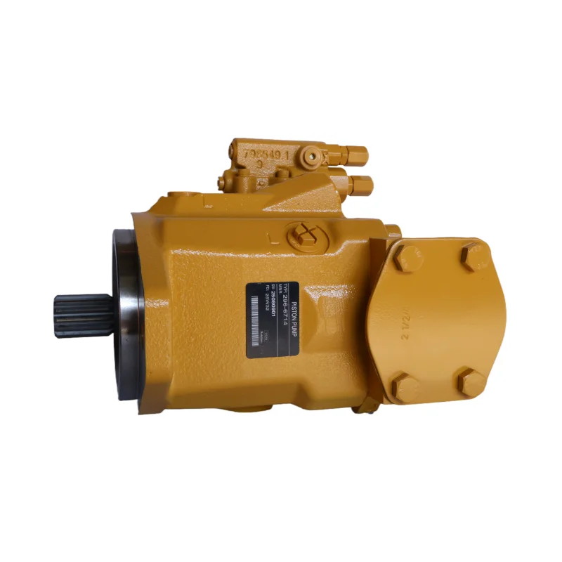


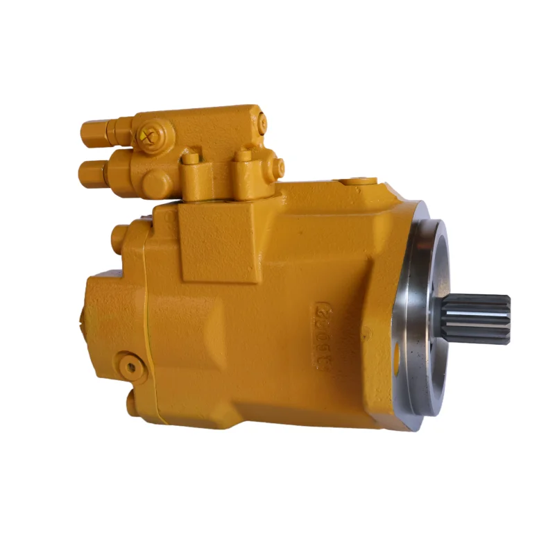
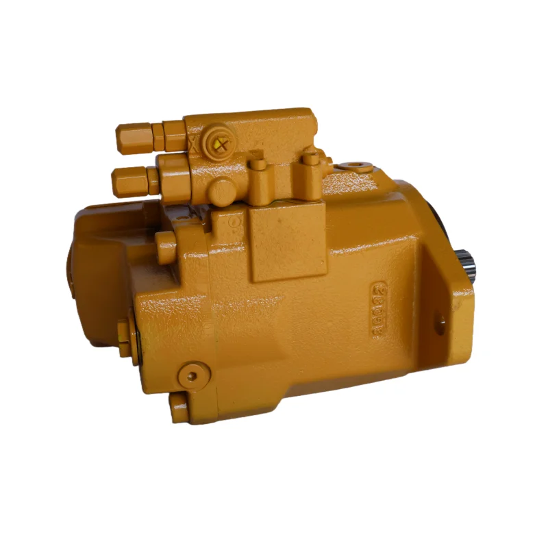

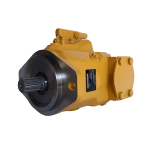
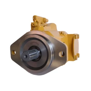
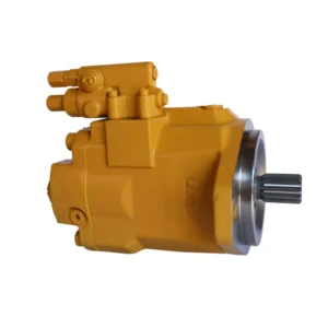
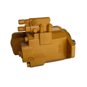
Oem Engine Parts Excavator C9 Engine Parts Fan Pump 259-0815 10R-8707 Hydraulic Fan Pump for Excavator E330D E336D
1.Displacement and flow rate
Theoretical displacement: 15 cc/rev (ml/RPM), suitable for the medium and low flow power requirements of the engine fan cooling system
2.Actual flow rate: At the rated speed of 1500 rpm, the output flow rate is approximately 22.5 L/min. At the maximum rotational speed of 2500 rpm, the maximum flow rate can reach 37.5 L/min, and the flow rate attenuation under load is ≤5% (at a pressure of 8MPa).
3.Work pressure
Continuous working pressure: 8.0 MPa (80 bar), suitable for low-pressure drive conditions of fan motors, with stable long-term operating pressure
4.Instantaneous peak pressure: 10.0 MPa (100 bar), single duration ≤5 seconds, capable of handling the impact load at the moment of fan startup
5.Rotational speed range
Rated speed: 800-2000 rpm, suitable for the speed output characteristics of the engine from idle speed to rated operating conditions
6.Maximum allowable speed: 2500 rpm, minimum stable speed ≥500 rpm, to prevent the fan from starting and stopping due to insufficient oil supply at low speeds
7.Structural form: External meshing spur gear pump, single-stage transmission structure, adopting an integrated casting design of “pump body + end cover”. The gear is made of 20CrMnTi alloy material, and has undergone carburizing, quenching and fine grinding treatment. The hardness of the tooth surface is HRC55-58, and the tooth side clearance is 0.04-0.06mm
8.Oil requirements
Applicable oil type: L-HM 46 anti-wear hydraulic oil is recommended. It is compatible with engine lubricating oil (in some integrated lubrication system scenarios), with a viscosity range of 20-200 mm²/s
9.Working oil temperature: -20℃ to 90℃. The oil cleanliness should reach ISO 18/15 grade (NAS 9 grade). The suction port is equipped with an 80μm screen filter, and the return port can be optionally equipped with a 10μm fine filter
10.Installation and adaptation
Installation type: Flange installation, conforming to SAE A 3 bolt standard. The shaft end is connected by Φ30mm flat key, keyway specification 8× 7mm
11.Oil port specifications: Oil inlet G1/2, oil outlet G1/2, supports unidirectional rotation (default clockwise), overall weight approximately 10kg, can be installed horizontally or vertically (when installed vertically, ensure sufficient oil suction)
twelve
Other parameters: Volumetric efficiency ≥90% (under rated conditions), total efficiency ≥85%, no-load noise value ≤75 dB (at 1500 rpm), with an internal simple unloading tank structureIi. Working Principle
This pump is an external meshing quantitative gear fan drive pump. Its core consists of the driving gear, driven gear, pump body, end cover and sealing assembly. It provides continuous hydraulic power to the fan motor through the volume change generated by gear meshing. The working process is divided into three stages and simultaneously meets the dynamic requirements of engine speed fluctuations.
1.The oil suction process: The engine drives the active gear of the pump body to rotate through the transmission mechanism. The meshing of the active gear drives the driven gear to rotate synchronously in the opposite direction. When the teeth of the gear on one side of the oil suction chamber gradually separate, the volume of the sealed cavity formed between the teeth increases, and the pressure inside the cavity is lower than the atmospheric pressure. The hydraulic oil is sucked into the cavity between the teeth through the oil inlet and the oil suction chamber, completing the oil suction action and ensuring the continuous supply of oil
2.The oil pressing process: The intertooth cavity filled with oil rotates to one side of the oil pressing cavity along with the gear. At this point, the teeth gradually interlock with each other, and the volume of the sealed cavity is forcibly compressed. The oil pressure rises to a working pressure of 8MPa and is then conveyed through the oil pressing cavity and the oil outlet to the fan hydraulic motor, driving the motor to rotate and the fan to run, achieving the conversion of mechanical energy into hydraulic energy and then into kinetic energy
3.Dynamic adaptation process: When the engine speed changes (such as from idle speed of 800 rpm to rated 2000 rpm), the output flow of the pump changes synchronously and linearly. Through the flow-speed characteristic matching of the fan motor, the fan speed is dynamically adjusted according to the engine load. Meanwhile, the simple unloading groove placed inside the pump body can eliminate the trapped oil phenomenon during gear meshing, avoiding noise or pressure shock when the speed fluctuates
Iii. Product Features and Advantages
1.Strong low-pressure stability and adaptability: The continuous working pressure of 8MPa precisely matches the driving requirements of the fan motor, avoiding energy waste in high-pressure systems. With a 15cc /rev displacement, it outputs a flow rate of 22.5L /min at 1500 rpm, capable of driving engineering fans with a diameter of no more than 1.2m to operate efficiently, meeting the cooling requirements of engines ranging from 200 to 300kW
2.Excellent wide speed range adaptation: With a speed adaptation range of 500-2500 rpm, it can cover the speed changes of all operating conditions such as engine idle, partial load, and rated load. The flow rate is linearly output with the speed, enabling the fan speed to match the engine’s heat dissipation requirements in real time. Compared with fixed-speed fans, it saves 15% to 20% of energy
3.Outstanding anti-pollution and reliability:
The clearance sealing feature of external meshing gears has a high tolerance for oil impurities. In the dusty and oily environment of the engine compartment, its service life can reach over 8,000 hours, which is 60% longer than that of vane pumps
4.The integrated cast pump body has a high structural strength and excellent vibration resistance (capable of withstanding a 10g vibration acceleration), making it suitable for the bumpy operation scenarios of construction machinery
5.Significant cost and maintenance advantages: The manufacturing cost is only 50% to 60% of that of a plunger pump with the same flow rate. The standardization degree of wear parts (gears, oil seals) is high, and the replacement cost is low. Without complex control components, troubleshooting only requires checking two core parameters, pressure and flow rate, which increases maintenance efficiency by 40%
Iv. Usage Functions and Purposes
1. Usage function
•As the power source of the fan hydraulic drive system, it outputs low-pressure stable oil to drive the fan motor to rotate, which forces the fan to dissipate heat from the engine radiator and intercooler, and controls the engine operating temperature within the optimal range of 85-95℃
•Adapt to the dynamic changes of engine speed, and achieve stepless adjustment of fan speed through linear flow output, avoiding energy waste caused by high-speed fan operation at idle speed and insufficient heat dissipation under high load
•It is equipped with an internal pressure protection feature. When the system pressure exceeds the peak of 10MPa, the pressure is naturally released through the unloading trough. Combined with the system relief valve, it achieves dual protection to prevent pump body damage caused by fan jamming
2. Uses
•In the field of construction machinery: Engine cooling systems for 20-30 ton excavators, 50 ton loaders, and medium-sized bulldozers, driving cooling fans to dissipate heat for the engine and hydraulic oil radiators
•In the commercial vehicle sector: Engine auxiliary cooling systems for heavy-duty trucks and buses, especially suitable for vehicles operating in high-altitude and high-temperature areas, enhance cooling efficiency
•Fixed power field: Cooling fan drive for 200-300kW diesel generator sets and small Marine engines to ensure stable temperature of the units during full-load operation
V. Applicable Machines and Scenarios
1. Applicable machines
•Construction machinery: 20-30 ton crawler excavators, 50 ton wheel loaders, medium-sized bulldozers
•Commercial vehicles: 12-18 ton heavy-duty trucks, large buses, and special operation vehicles (such as concrete mixer trucks)
•Fixed equipment: 200-300kW diesel generator sets, 50-100 horsepower Marine engines
2. Applicable scenarios
•High-temperature operation scenarios: Construction machinery for outdoor work in summer, commercial vehicles operating in desert areas, and generator sets in enclosed machine rooms require high-intensity and continuous heat dissipation
•Load fluctuation scenarios: The excavation-idle cycle operation of excavators, the heavy-load and light-load driving of trucks, and the variable load power supply of generator sets require dynamic adaptation of fan speed
•Harsh environmental scenarios: Mining sites, construction demolition sites, ports and docks, and other environments with a lot of dust. It operates stably relying on its strong anti-pollution property
Six. Similar models
1. Models of the same series
•259-0810: Theoretical displacement 10 cc/rev, rated flow 15 L/min (1500 rpm), continuous pressure 8MPa, suitable for small engines ranging from 100 to 200kW, such as light trucks and small generator sets
•259-0820: Theoretical displacement 20 cc/rev, rated flow 30 L/min (1500 rpm), continuous pressure 8MPa, suitable for large engines ranging from 300 to 400kW, such as heavy-duty excavators and large Marine engines
2. Similar alternative models
•CB-F15: Low-pressure external gear pump, displacement 15 cc/rev, continuous pressure 8MPa, volume comparable to 259-0815, compatible with general engine cooling systems, and lower cost
•GP15 series: Internal gear pump, displacement 15 cc/rev, continuous pressure 7MPa, noise value ≤70 dB (1500 rpm), suitable for bus and machine room generator sets with high noise requirements
Vii. Precautions for Use
1.Core norms for Oil and Fluid Management
Strictly use L-HM 46 anti-wear hydraulic oil. If the oil is shared with the engine lubrication system, it is necessary to ensure that the oil meets the viscosity requirements of both the engine and the pump at the same time. It is strictly forbidden to mix oils of different grades to avoid gear sticking
2.The oil suction port filter should be inspected every 1000 hours. If the clogging degree exceeds 50%, it needs to be cleaned or replaced. Hydraulic oil should be sampled and tested every 2000 hours. It must be replaced when emulsification or oxidation (acid value ≥ 2.0mgKOH /g) occurs
3.Installation accuracy control
The elastic coupling is adopted to connect with the engine transmission mechanism. The coaxiality error of the two shafts is ≤ 0.15mm, and the angular error is ≤1°, to avoid excessive radial force causing the pump shaft to bend and affecting the stability of the flow output
4.The length of the oil suction pipeline is no more than 1.5m, the diameter is no less than Φ32mm, and the number of elbows is no more than 1 to reduce the oil suction resistance. When installed vertically, the oil suction port of the pump body should be more than 300mm lower than the liquid level of the oil tank to prevent cavitation
5.Startup and operation monitoring
Before starting the engine for the first time, manually rotate the pump shaft 2 to 3 turns to ensure there is no jamming. After starting, idle for 3 to 5 minutes until the oil temperature rises above 20℃, then gradually increase the speed to avoid insufficient gear lubrication during cold starts
6.Core parameters to be monitored during operation: Oil temperature ≤90℃ (if it exceeds 95℃, the cooling system needs to be checked), outlet pressure ≤8MPa (long-term overpressure will lead to accelerated gear wear). If a “buzzing” abnormal sound occurs, it is mostly due to insufficient oil absorption. It is necessary to check the oil level or the filter
7.Maintenance and upkeep nodes
Check the sealing condition of the shaft seal every 2000 hours. If the leakage exceeds 5 drops per minute, replace the oil seal (fluororubber material is recommended, suitable for wide-temperature scenarios). Disassemble and inspect the gears every 6,000 hours. When the wear on the tooth surface exceeds 0.15mm, the gear pair needs to be replaced
8.For pump bodies that have been stored for a long time, anti-rust oil should be injected and the oil ports sealed to prevent the gears from rusting. Before installation, the interior of the pump body should be rinsed with clean oil to remove any residual anti-rust oil
9.Safety Precautions
Before maintenance, the engine should be shut down. Wait until the pump body pressure is completely unloaded (the pressure gauge shows 0MPa) and the oil temperature drops below 40℃ before disassembling to prevent oil from spraying and injuring people
10.After replacing gears or seals, a 10-minute no-load test run should be conducted to ensure there is no leakage or abnormal noise before loading and running to avoid equipment damage caused by assembly errors


