


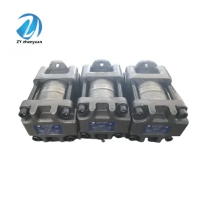


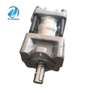
Hydraulic Gear Pump QT31 QT41 QT51 QT61 QT32 QT42 QT52 QT62 QT33 QT43 Series QT33-10F-Z High Pressure Hydraulic Pump
Core performance parameters
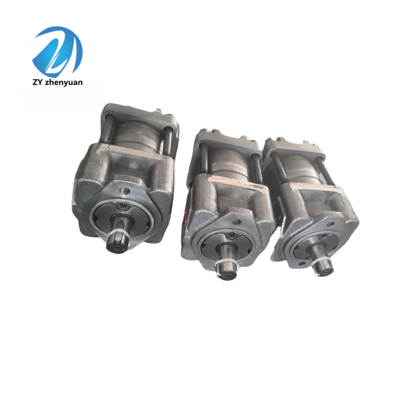
– Pump type: Fixed displacement vane pump, single-acting structure, right-rotating direction, suitable for medium and low pressure open hydraulic circuits, stable output flow, providing medium pressure oil supply for single or multiple actuators of small and medium-sized equipment.
– Displacement and pressure parameters: Rated displacement 10 mL/r (estimated based on model “10”); Rated working pressure: 16 MPa, maximum allowable pressure: 18 MPa (for a duration of ≤10 seconds); Rated speed: 1500 r/min, maximum speed: 2000 r/min (short time ≤5 minutes).
– Flow and efficiency parameters: Output flow at rated speed is 15 L/min, and the flow pulsation rate is ≤3%. Volumetric efficiency ≥90%, total efficiency ≥82%; The imported vacuum degree is ≤0.03 MPa (under rated working conditions).
– Operating characteristics: Continuous operating oil temperature ≤60℃, maximum allowable oil temperature 80℃; Noise value ≤75 dB (measured at 1 meter); The fault-free operating life under rated conditions is ≥ 8,000 hours.
2. Structure and connection parameters
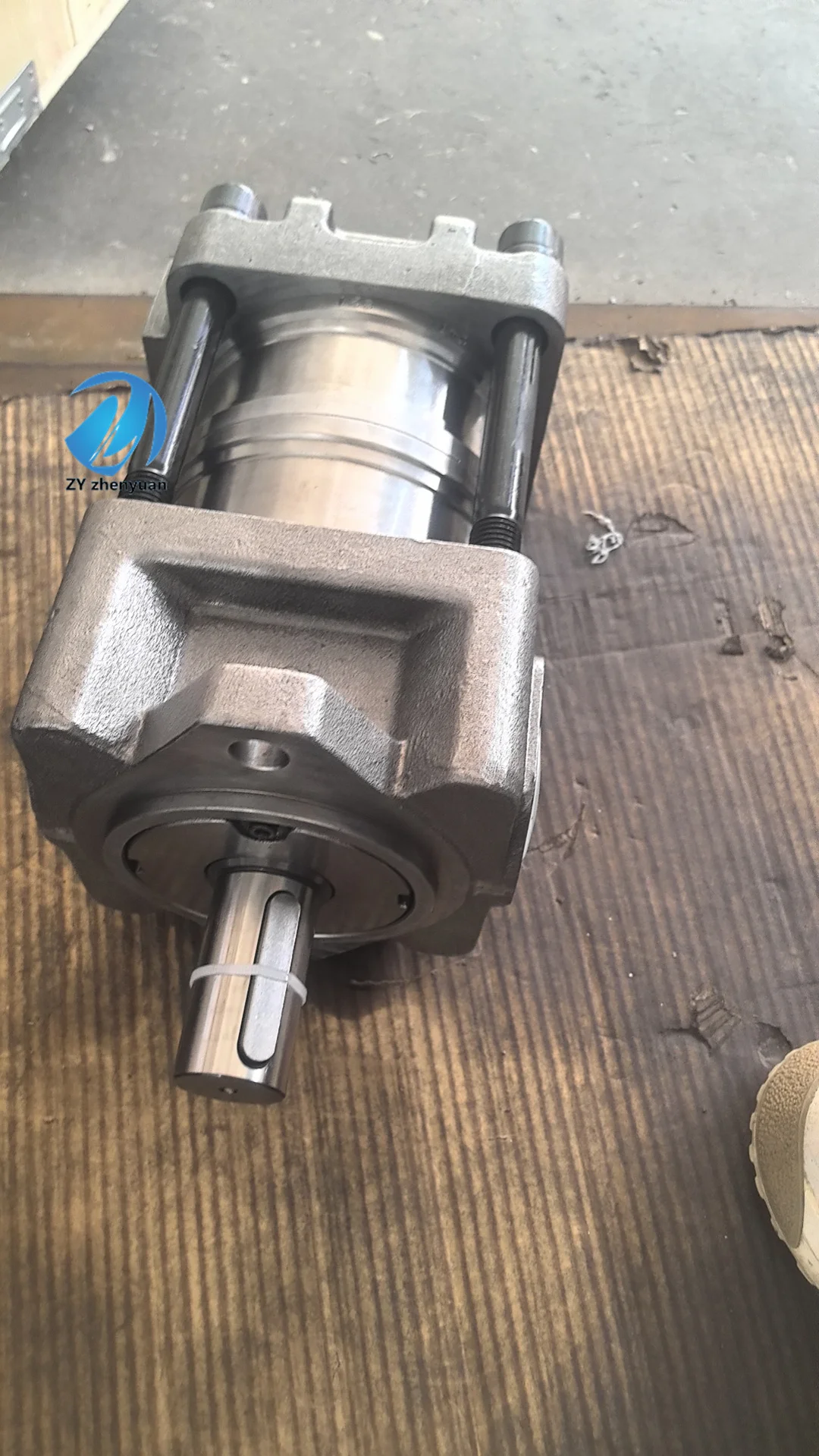
– Structural type: Quantitative vane pump structure, integrating rotor, stator, vanes, oil distribution plate and end cover; The eccentric stator design is adopted, and the blades slide in the rotor slots to achieve oil suction and discharge. It is equipped with an internal pressure relief valve and an oil replenishment valve, and is fitted with a coupling guard cover.
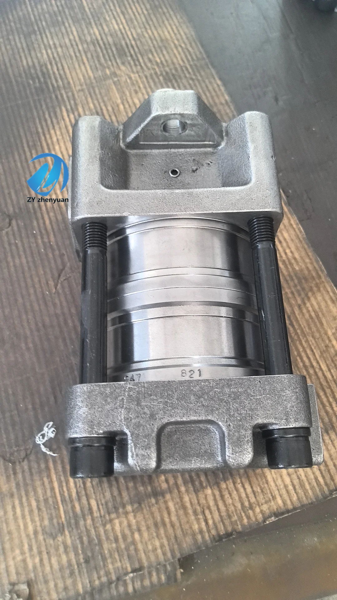
– Core material: The pump body is made of gray cast iron HT250 (aged treatment); The rotor is made of alloy cast iron QT600-3. The blades are made of high-speed steel W18Cr4V (quenched treatment, hardness HRC58-62). The sealing parts are made of oil-resistant nitrile rubber (temperature resistance ≤100℃).
– Connection specifications: The oil suction port (S) has a G1/2 thread, and the oil outlet port (P) has a G3/8 thread. The drive shaft is connected by a flat key (specification 6×16). The installation method is horizontal flange installation, with a bolt center distance of 120×80 mm. The weight of the pump body is approximately 18 kg, and its external dimensions (length × width × height) ≈320×200×250 mm.
3. Medium and Environmental requirements
– Medium requirements: L-HM 32/46 anti-wear hydraulic oil is suitable for normal temperature. L-HM 22 can be selected for low-temperature environment. The allowable viscosity of the medium is 15-300 mm²/s, and the moisture content is ≤0.05%. It is strictly prohibited to use media containing solid particles (particle size > 10 μm) or corrosive media.
– Cleanliness standard: The oil cleanliness should reach ISO 4406 16/13 grade. It is recommended to install a 10 μm filter in front of the oil suction port. The filter element should be replaced when the pressure difference of the filter is greater than 0.1 MPa.
– Environmental parameters: Operating environment temperature -10℃ to 80℃, relative humidity ≤95% (short-term condensation is allowed); With a protection grade of IP54, it is suitable for scenarios such as small-scale construction machinery, light industrial equipment, and machine tool hydraulic systems.Ii. Working Principle
This pump is an eccentric quantitative vane pump. Its core achieves continuous oil suction and discharge through the mechanism of “rotor rotation – vane extension and contraction – periodic volume change”. The specific process is as follows:
1. Core process of oil suction and discharge
The motor drives the rotor to rotate around the center of the eccentrically installed stator. Under the action of centrifugal force and root pressure oil, the blades in the rotor slots are always in close contact with the inner surface of the stator. When the blades rotate with the rotor to the oil suction area on the inner surface of the stator that is far from the center of the rotor, the blades extend outward. The closed volume formed by the adjacent blades, the rotor, the stator and the oil distribution plate gradually increases, creating a negative pressure. The hydraulic oil is then sucked in through the oil suction port and the oil suction chamber of the oil distribution plate. When the blades rotate to the oil pressure zone on the inner surface of the stator that is closer to the center of the rotor, the inner surface of the stator forces the blades to retract inward, and the sealed volume shrinks sharply. The oil is then squeezed and discharged through the oil distribution plate’s oil pressure chamber and the oil outlet, completing the oil suction and discharge cycle.
2. Voltage stabilization and protection mechanism
– Pressure stability: Equipped with a built-in high-pressure relief valve, when the system pressure exceeds 18 MPa, it automatically unloads and returns the overpressurized oil to the oil suction chamber to maintain system pressure stability. The oil distribution pan adopts a balanced design to reduce pressure shock.
– Operation protection: The oil suction chamber is equipped with an internal oil replenishment valve. When the vacuum degree at the inlet is too high, it will automatically open to replenish oil to prevent dry friction of the blades due to insufficient oil supply. Pressure oil is introduced into the root of the blade to ensure that the blade can still closely adhere to the stator at low speeds, avoiding insufficient oil absorption.
Iii. Product Features and Advantages
– Strong medium pressure quantitative adaptability: With a rated pressure of 16 MPa and a displacement of 10 mL/r, a stable flow rate of 15 L/min, it precisely matches single or multiple actuators of 5-15 ton equipment, taking into account both medium pressure power and flow stability, and is suitable for continuous operation scenarios in medium and low pressure.
– Low noise and smooth operation: The eccentric stator and the curved surface fit design of the blades reduce motion impact. The operating noise is ≤75 dB, which is 8-10 dB lower than that of the same displacement plunger pump. The flow pulsation rate is ≤3% to avoid equipment vibration caused by system pressure fluctuations.
– Simple structure and easy maintenance: It adopts a modular design, and the rotor, blades, oil distribution plate and other vulnerable parts are easy to disassemble and assemble. There is no complex variable mechanism, with fewer failure points. Daily maintenance only requires regular replacement of oil and filter elements, and the maintenance cost is 40% lower than that of variable pumps.
– Good anti-pollution ability: The fit clearance between the blades and the stator is larger than that of the plunger pump, and the requirement for oil cleanliness is lower than that of the high-pressure plunger pump (ISO 4406 16/13 grade is sufficient), making it suitable for light industry and small-scale engineering scenarios with a lot of dust.
– Cost-effectiveness and high performance: The manufacturing cost is over 35% lower than that of axial piston pumps of the same displacement, and there are no high-frequency and easily damaged proportional control components. Both the initial investment and long-term operation and maintenance costs have advantages, making it suitable for the equipment needs of small and medium-sized enterprises.
Iv. Usage Functions and Purposes
1. Core usage functions
Medium-pressure quantitative oil supply: It provides a stable flow rate of 15 L/min for medium and low-pressure systems, meeting the oil supply requirements for uniform operation of actuators (such as machine tool feed, small conveyor drive) and intermittent actions (such as small clamping devices).
– Multi-loop diversion adaptation: The output oil is distributed to 2-3 light-load actuators through multi-way valves to achieve multi-action alternating operation (such as the sequential operation of multiple cylinders in a small hydraulic workstation), enhancing the system integration.
– System pressure stabilizing and oil replenishment: It can be used as an auxiliary oil replenishment pump for high-pressure systems, providing oil to the suction chamber of the high-pressure pump, reducing the vacuum degree at the pump inlet, preventing cavitation damage, and extending the service life of the main pump.
2. Main application fields
In the field of small-scale construction machinery: 5-10 ton small loaders (steering circuits), 8-12 ton small excavators (auxiliary action circuits), 3-5 ton forklifts (lifting circuits), suitable for short-distance operations in urban and rural areas and warehouse loading and unloading scenarios.
– Light industry and machine tool fields: Small CNC lathes (lubrication and clamping circuits), plastic blow molding machines (clamping circuits), small strapping machines (pressing circuits), suitable for continuous operation under medium and low loads in factories.
– Agriculture and municipal sectors: Large tractors (suspension mechanism drive circuits), small water sprinklers (pump drive circuits), municipal maintenance equipment (small hydraulic pick drive circuits), suitable for outdoor intermittent operations.
V. Applicable Machines and Scenarios
1. Adapt to the core machine
– Small-scale construction machinery: 5-10 ton wheel loaders, 8-12 ton crawler excavators, 3-5 ton internal combustion forklifts, small hydraulic breakers.
– Light industry and machine tool equipment: small CNC lathes, plastic blow molding machines (50-100 tons), waste paper balers (10-30 tons), small hydraulic presses (50-100 tons).
– Agricultural and municipal equipment: Large wheeled tractors, small water sprinklers (3-5 tons), small municipal maintenance excavators (6-8 tons), small garbage compression equipment.
2. Typical application scenarios
– Small CNC lathe scenario: As the main pump of the lubrication and clamping circuit for small CNC lathes, it outputs a flow rate of 15 L/min, of which 5 L/min is used for spindle lubrication and 10 L/min for chuck clamping. The pressure is stable at 8-10 MPa, with low operating noise, making it suitable for the precision processing environment in workshops.
– Small baler operation scenario: It is equipped with a 20-ton waste paper baler, providing 16 MPa pressure oil to the pressing cylinder with a flow rate of 15 L/min to ensure the uniform advancement of the pressing cylinder. After the waste paper is compressed, the relief valve unloads it. Compared with traditional gear pumps, it saves 20% energy and is suitable for continuous operation in waste recycling stations.
– Small loader steering scenario: It is used in the steering circuit of 8-ton small loaders, providing 12-14 MPa pressure oil to the steering cylinder with a flow rate of 15 L/min to ensure flexible steering. The low noise feature meets the noise control requirements during urban road construction.
Six. Similar models
1. Alternative models of the same series
-QT33-08F-Z: A small-displacement model of the same structure, with a rated displacement of 8 mL/r and an output flow rate of 12 L/min. The pressure parameters are consistent. It is suitable for small equipment under 5 tons (such as 3-ton forklifts), and the cost is 15% lower than the original model.
-QT33-12F-Z: A mid-displacement model in the same series, with a rated displacement of 12 mL/r, an output flow rate of 18 L/min, and the same pressure parameters. It is suitable for 15-20 ton equipment (such as the auxiliary circuit of a 12-ton excavator), but its cost is 20% higher than that of the original model.
2. Cross-series alternative models
-QT33-10F-L: Left-rotating model, with exactly the same structure and parameters, suitable for power sources with left-rotating drive shafts (such as some small diesel engines), and the cost is the same as the original model.
-QT33-10F-H: High-temperature compatible model. The temperature resistance of the sealing parts has been increased to 120℃, and the blade material has been upgraded to hard alloy. It is suitable for high-temperature scenarios such as metallurgical auxiliary equipment. The cost is 35% higher than that of the original model.
-QT44-10F-Z: A high-pressure upgraded model with a rated pressure of 20 MPa. The displacement and flow parameters are consistent, suitable for medium and high-pressure light-load scenarios (such as small high-pressure clamping devices). The cost is 40% higher than that of the original model.
Vii. Precautions for Use
1. Medium management
At normal temperature, L-HM 32/46 anti-wear hydraulic oil is selected. At low temperature (-10℃ to 0℃), L-HM 22 is selected. It is strictly prohibited to mix different grades or deteriorated oils. Before the new pump is used for the first time, the pipeline should be flushed with clean oil for ≥10 minutes to ensure that the cleanliness meets ISO 4406 16/13 grade.
– Check the pressure difference of the oil suction filter every month (replace the filter element when it exceeds 0.1 MPa), test the moisture content of the oil every two months (≤0.05%), and take samples to test the cleanliness every quarter. When emulsification, discoloration or sedimentation at the bottom of the oil is detected, stop the machine immediately to change the oil and clean the pump body.
2. Installation and commissioning
When installing, ensure that the coaxiality of the drive shaft and the motor shaft is ≤ 0.08mm (connected by an elastic coupling), and the flange bolts are evenly tightened with a torque of 200 N·m. The diameter of the oil suction pipeline should be ≥G1/2, the length ≤ 2m, and the number of elbows should not exceed 2 to avoid excessive oil suction resistance causing cavitation.
Before debugging, add hydraulic oil to the upper limit of the oil level gauge in the oil tank, and manually turn the wheel 3 to 5 times to confirm there is no jamming. Jog the motor to verify the rotation direction (right rotation), run it at low speed (1000 r/min) without load for 5 minutes, then gradually increase it to the rated speed, and detect that the outlet pressure is stable at 16 MPa.
The oil suction port should be at least 300mm lower than the oil level in the oil tank to prevent it from being sucked empty. A 0-25 MPa pressure gauge is installed at the oil outlet for convenient pressure monitoring. For outdoor installation, a rain cover should be added to ensure that the protection level remains at IP54. After the pipelines are connected, they need to be vented to prevent the formation of air cavities.
3. Operation and Maintenance
During operation, real-time monitoring of the pump body temperature (normal ≤60℃, maximum not exceeding 80℃), outlet pressure and noise is carried out. If the temperature rises sharply by more than 10℃, the pressure fluctuates by more than 1 MPa, or the noise abnormally increases (> 80 dB), stop the machine immediately for inspection, with a focus on checking the cleanliness of the oil or the wear of the blades.
Regular maintenance should be carried out every 1500 hours: clean the oil suction filter screen and the relief valve, and check the fit clearance between the blades and the stator (replace the blades when the clearance is greater than 0.02mm). Replace the hydraulic oil and seals, and recalibrate the relief valve pressure to 18 MPa.
No-oil idling is strictly prohibited (idling for more than 5 seconds may cause dry grinding damage to the blades and stator). It is strictly prohibited to operate at an excessive speed (> 2000 r/min) or under long-term overpressure (> 18 MPa). Avoid frequent starts and stops. The interval between each start and stop should be no less than 30 seconds.
4. Storage protection
When stored for a long time, use special plugs to block the oil suction port and the oil outlet, inject anti-rust oil into the pump body, and apply grease to the keyway of the drive shaft. Store in a dry and well-ventilated warehouse with a temperature ranging from 0 to 40℃ and a humidity of no more than 60%. Avoid direct sunlight and heavy object compression. Manually turn the machine once every three months to prevent component adhesion.
Before putting the pump into use after being idle for more than 12 months, thoroughly clean the inner cavity of the pump and replace all the seals. After adding new hydraulic oil, conduct a low-speed test run for 1 hour to check the pressure stability and leakage. Once no abnormalities are confirmed, connect it to the system for use.


