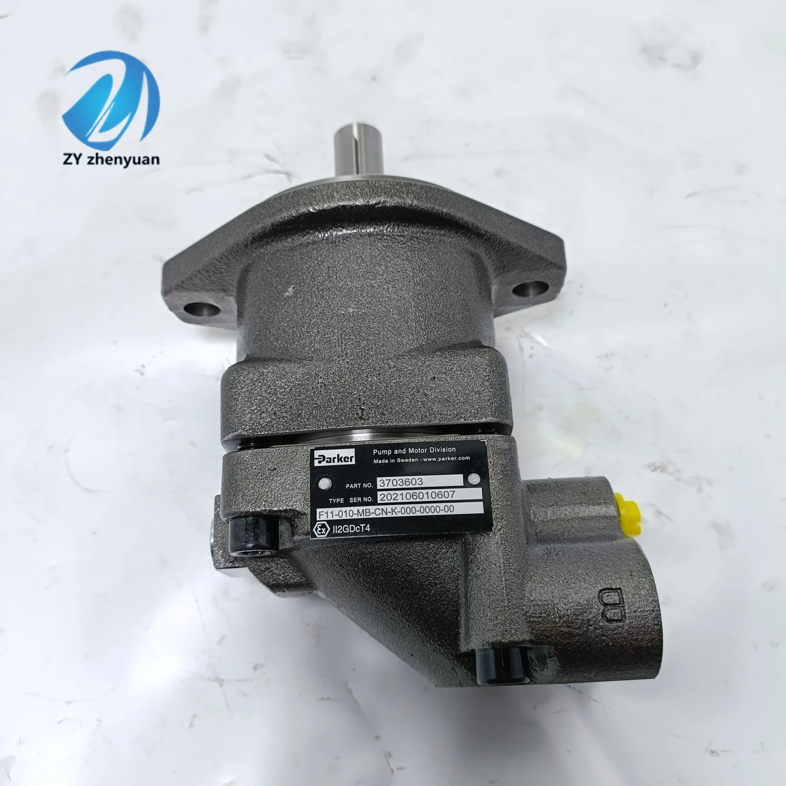


Hydraulic Piston Motor F12 F11-005/006/010/012/014/019/150/250 Series F11-010-MB-CV-K-000-0000-00 High Torque Hydraulic Motor
1. Basic performance parameters- Motor type: Axial piston type variable hydraulic motor, with pressure compensation variable control, unidirectional/bidirectional rotation adaptation, suitable for small and medium-sized hydraulic power systems
– Displacement parameters: Rated displacement 10 mL/r, variable adjustment range 3-10 mL/r (stepless variable), displacement control accuracy ±5%
– Pressure parameters: Rated working pressure 21 MPa, maximum allowable pressure 28 MPa (short-term ≤10 seconds), return oil back pressure ≤1.5 MPa (if exceeded, a relief valve needs to be connected)
– Speed and Torque: Rated speed 2000 r/min, maximum speed 3000 r/min (short time ≤5 minutes), minimum stable speed 50 r/min; Rated torque 65 N·m, maximum torque 90 N·m (corresponding to maximum pressure)
– Efficiency parameters: Rated working condition volumetric efficiency ≥92%, total efficiency ≥86%; The efficiency fluctuation during variable adjustment is ≤5%
2. Structure and connection parameters
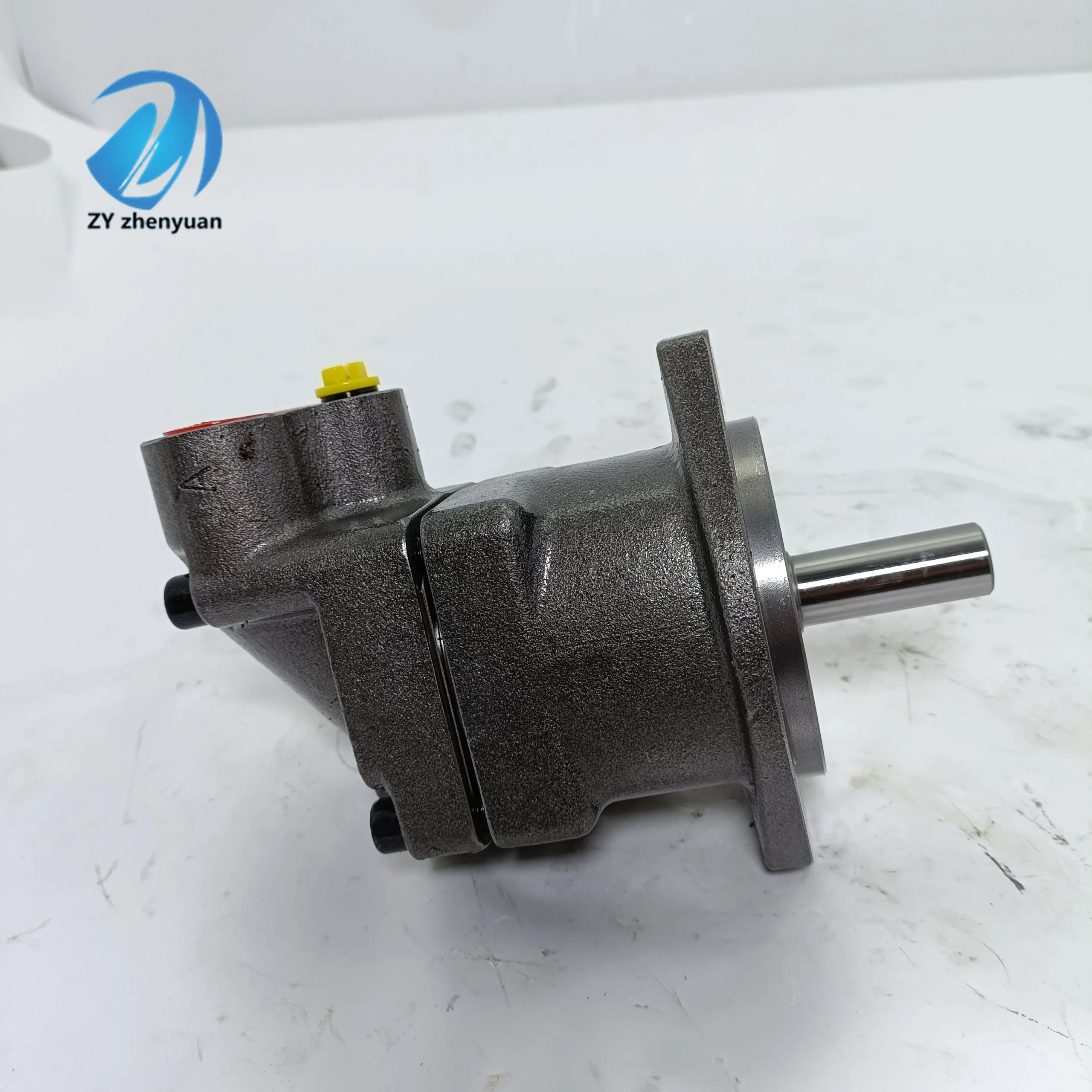
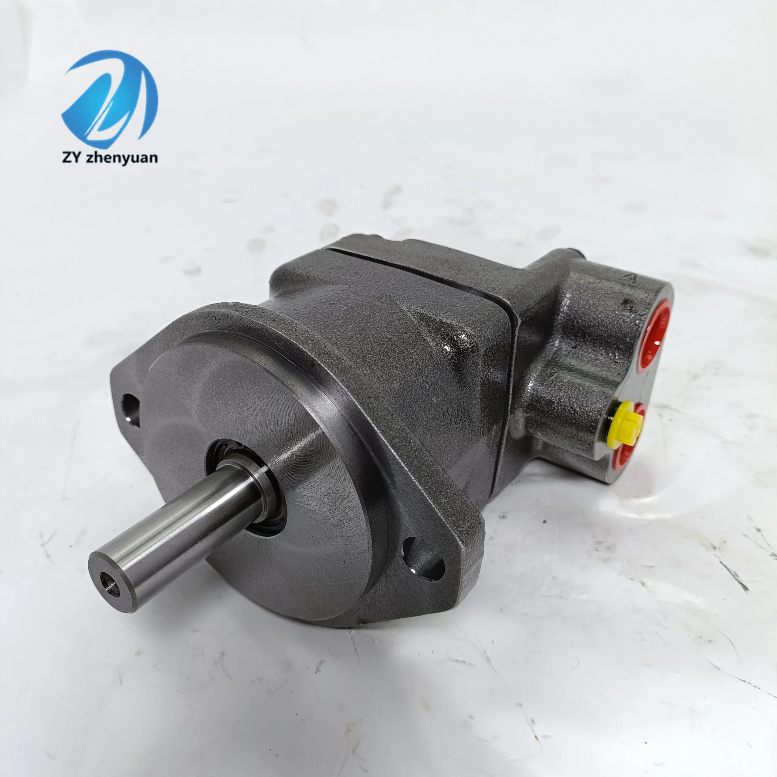
– Structural type: Swash plate axial piston structure, integrated pressure compensation variable mechanism, bidirectional check valve, mechanical braking device (optional); The centering spring is adopted to position the plunger, and the pressure self-compensation design of the distribution plate is adopted
– Core material: The plunger is made of chromium-molybdenum alloy steel (surface nitrided treatment, hardness HRC60-63); The cylinder block is made of tin bronze alloy (precision honing). The swash plate is made of alloy steel substrate + ceramic coating. The sealing part is a high-pressure resistant fluororubber combination (temperature resistance ≤110℃).
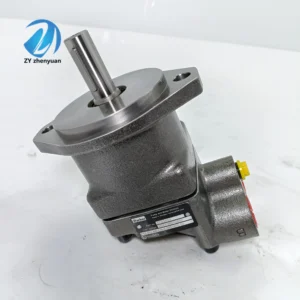
– Connection specifications: Threaded connection of oil ports (Inlet A and return B are G1/4, control port X is G1/8); The output shaft is connected by a flat key (specification 8×20). The installation method is flange installation (compatible with ISO 3019-1 standard); The overall weight is approximately 8 kg, and the external dimensions (length × width × height) ≈220×180×160 mm
3. Medium and Environmental requirements
– Medium requirements: L-HM 46 anti-wear hydraulic oil is suitable for normal temperature. L-HM 32 is selected for low-temperature environment (below -20℃). The allowable medium viscosity is 10-400 mm²/s, the moisture content is ≤0.02%, and the solid particle size is ≤10 μm
– Environmental parameters: The cleanliness of the oil should reach ISO 4406 14/11 grade; The operating environment temperature ranges from -30℃ to 90℃, with a relative humidity of no more than 95%. The protection grade is IP65, making it suitable for industrial machinery, small construction machinery and other scenarios
Ii. Working Principle
This motor is an axial plunger type variable hydraulic motor. Its core converts hydraulic energy into mechanical energy through the mechanism of “high-pressure oil-driven plunger – mechanical force conversion – variable mechanism regulation”, achieving power output and speed regulation. The specific process is as follows
1. Core mechanism of power transformation
The high-pressure oil of the hydraulic system enters the motor cylinder through the oil inlet A, pushing the plunger to extend outward along the cylinder hole, with the top of the plunger closely adhering to the end face of the swash plate. Due to the fixed inclination Angle of the swash plate, a normal force is exerted on the swash plate during the extension of the plunger. This force is decomposed into axial force and circumferential force. The circumferential force drives the cylinder body to rotate around the output shaft, converting hydraulic energy into mechanical energy and outputting power through the output shaft. When reverse rotation is required, simply switch the direction of oil intake and return (high-pressure oil is connected to port B), the force direction of the plunger changes, and the cylinder body rotates in reverse.
2. Variable adjustment mechanism
Pressure compensation variable control is adopted: when the system load pressure increases, the X pressure at the control oil port rises synchronously, pushing the variable mechanism to reduce the swash plate inclination Angle, shortening the effective stroke of the plunger, and reducing the motor displacement. When the load pressure drops, the centering spring pushes the swash plate to return to its original position, increasing the displacement and achieving “load adaptive speed regulation” to maintain a stable output torque. The minimum displacement (3 mL/r) can be limited by adjusting the screw of the variable mechanism, which is suitable for low-speed and high-torque working conditions.
3. Protection mechanism
The built-in double-direction check valve prevents the backflow of oil from causing the motor to idle. When the system pressure exceeds 28 MPa, the variable mechanism forcibly reduces the displacement to avoid overload. The distribution plate adopts a pressure self-compensation design. After wear, it automatically adheres to the cylinder body to maintain volumetric efficiency. Optional mechanical braking device. When power is off, the shaft end braking is achieved through a spring to prevent the load from sliding down.
Iii. Product Features and Advantages
– Precise and efficient variable regulation: The pressure compensation variable mechanism enables the displacement to dynamically adapt to the load, saving over 30% energy compared to fixed-displacement motors. It features a wide range of 3-10 mL/r stepless adjustment, with a speed regulation ratio of up to 10:1, and is suitable for multi-condition switching from “low speed with high torque to high speed with low torque”
– Compact structure and high power density: With a 10 mL/r small displacement design, the rated torque reaches 65 N·m, and the power density is 40% higher than that of gear motors of the same displacement. The 8kg lightweight structure reduces the installation space by 30% compared to the same performance plunger motor, making it suitable for small equipment
– Strong anti-wear and durability: The wear-resistant combination of ceramic-coated swash plate and nitrided plunger, in conjunction with the pressure self-compensating distribution plate, ensures a fault-free operating life of ≥ 10,000 hours under rated conditions. It can withstand a high-pressure impact of 28 MPa and is suitable for scenarios with frequent load fluctuations
– Easy operation and wide adaptability: Supports bidirectional rotation without the need for additional reversing devices; The variable adjustment response time is ≤50 ms, and there is no shock during the switching process. It can be adapted to various control methods such as mechanical, hydraulic and electrical control, and is compatible with different system designs
Iv. Usage Functions and Purposes
1. Core usage functions
– Variable power output: It provides a power source with adjustable torque and speed for small and medium-sized machinery. The displacement is automatically adapted through load pressure feedback, replacing the combination of “quantitative motor + throttle valve” and reducing energy loss
– Bidirectional speed regulation drive: Supports forward and reverse stepless speed regulation, suitable for equipment that requires reciprocating motion (such as small grasping mechanisms, rotary worktables), with a speed regulation range of 50-3000 r/min, meeting the speed requirements of different operations
– Load stability control: The pressure compensation mechanism ensures stable torque when the load changes, avoiding the problem of “sudden drop in speed as the load increases”, and is suitable for precision transmission scenarios (such as roller drive for small printing machines).
2. Main application fields
– Industrial machinery field: Roller drive for small printing machines, feeding mechanisms for packaging machinery, indexing disk drive for CNC machine tools, roller drive for textile machinery, suitable for precision transmission scenarios in workshops
In the field of construction machinery: 1-3 ton small excavator slewing mechanisms, micro loader traveling drives, and small crane luffing mechanisms, suitable for outdoor medium and small-sized construction scenarios
In the field of agriculture and special machinery: small combine harvester header drive, orchard picking machinery rotating arm drive, small ship deck machinery (such as small winches), suitable for light-load high-frequency operation scenarios
V. Applicable Machines and Scenarios
1. Adapt to the core machine
– Industrial equipment: Small gravure printing machines, fully automatic packaging machines, CNC vertical lathes (indexing discs), high-speed textile winding machines
– Construction machinery: 1-3 ton crawler mini excavators, 0.5-1 ton micro wheel loaders, and small truck cranes under 5 tons
– Special equipment: Small combine harvesters, orchard lifting picking platforms, small ship winches, medical equipment (such as rehabilitation training equipment)
2. Typical application scenarios
– Small excavator rotation scenario: As a 2-ton small excavator rotation motor, when the system pressure is 21 MPa, the displacement is 10 mL/r, the output torque is 65 N·m, and the rotational speed is 150 r/min, driving the rotation platform to rotate smoothly 360°. When the load increases (such as when digging hard soil), the displacement automatically drops to 5 mL/r, and the torque remains stable to prevent engine overload. With IP65 protection, it is suitable for dusty environments on construction sites
– Packaging machine feeding scenario: When driving the fully automatic packaging machine feeding roller conveyor with a rated pressure of 18 MPa and a displacement of 8 mL/r, the rotational speed is 500 r/min, ensuring uniform feeding speed. When changing materials, the displacement is adjusted to 3 mL/r and the rotational speed is reduced to 180 r/min through the variable mechanism to achieve low-speed precise alignment. The volumetric efficiency is 92%, ensuring that the feeding error is ≤±1 mm
– Small winch drive scenario: Equipped with a 5-ton small ship winch, when lifting light loads (≤2 tons), the displacement is 10 mL/r, and the rotational speed is 300 r/min to achieve rapid lifting. When lifting a heavy load (5 tons), the pressure rises to 28 MPa, the displacement automatically drops to 4 mL/r, the rotational speed is 120 r/min, and the torque reaches 90 N·m, meeting the lifting requirements for heavy loads
Six. Similar models
1. Different models of the same series displacement
-F11-008-MB-CV-K-000-0000-00: A small-displacement model of the same structure, with a rated displacement of 8 mL/r, a rated torque of 52 N·m, and a maximum speed of 3500 r/min. It is suitable for micro devices (such as medical rehabilitation equipment), and its cost is 18% lower than that of the original model
-F11-016-MB-CV-K-000-0000-00: A large-displacement model of the same series, with a rated displacement of 16 mL/r, a rated torque of 104 N·m, and a maximum speed of 2500 r/min. It is suitable for medium-sized equipment (such as 5-ton loader travel), and its cost is 40% higher than that of the original model
2. Different models with the same displacement control mode
-F11-010-MB-CC-K-000-0000-00: Constant power control model, rated pressure 21 MPa, power stable at 14 kW, suitable for scenarios with large load fluctuations (such as injection molding machine feeding mechanisms), cost 25% higher than the original model
-F11-010-MB-MM-K-000-0000-00: Manual variable model, with displacement adjusted by mechanical handle, suitable for fixed equipment with stable load (such as small conveyor belts), and the cost is 22% lower than the original model
-F11-010-MB-EC-K-000-0000-00: Electro-hydraulic proportional control model, supporting PLC remote adjustment of displacement, control accuracy ±2%, suitable for automated production lines (such as CNC dividing plates), with a cost 50% higher than the original model
3. Different models with different installation methods
-F11-010-MB-CV-F-000-0000-00: Foot-mounted model, suitable for equipment without flange installation space. Other performances are the same as the original model, and the cost is basically the same
F12-090-MF-IV-D-000-0000-00
F12-110-MF-IV-D-000-0000-00
F11-005-MB-CV-K-000-0000-00
F11-010-MB-CV-K-000-0000-OT
F12-110-MS-SV-S-000-0000-0
F12-090-MS-SV-S-000-0000-0
F12-040-MF-IV-D-000-0000-0
F12-060-MF-IV-D-000-0000-0
F12-040-MF-IV-K-000-0000-0
F12-060-MF-IV-D-000-0000-P0
F12-040-MS-SV-S-000-0000-0
F12-060-MF-IV-K-000-0000-0
F11-005-MB-CV-K-000-0000-00
F11-010-MB-CV-K-000-0000-00
F11-010-HU-CV-K-000-000-0
F12-080-MF-CV-C-000-000-0
F12-080-MF-IV-D-000-0000-00
F12-090-MF-IV-D-000-0000-00
F12-110-MF-IV-D-000-0000-00
F11-005-MB-CV-K-000-0000-00
F11-010-HU-CV-K-000-000-0
F12-060-MF-IV-D-000-0
F12-080-MF-IV-D-000-0
F12-090-MF-IV-D-000-0
F12-110-MF-IV-D-000-0
F12-090-MS-SV-S-000-000-0
F12-110-MS-SV-S-000-000-0
F11-005-MB-CV-K-000-0000-0T 3782009
F11-005-MB-CV-K-000-000-0 3707249
F11-010-MB-CV-K-000-0000-0T
F12-060-MF-IV-D-000-000-0 3799988
F11-005-MB-CN-K-000-0000-00 3703665
F12-080-MF-IV-D-000-0000-00
F12-110-MF-IV-D-000-0000-00
Vii. Precautions for Use
1. Medium and Selection management
Strictly select L-HM 32/46 anti-wear hydraulic oil. It is strictly prohibited to mix different grades of oil or use oil containing impurities or with high moisture content. Select the type based on the system’s maximum pressure (≤21 MPa) and torque requirement (≤65 N·m). Overpressure operation is strictly prohibited to prevent the plunger from sintering
Before the new system is used for the first time, the pipelines and motor cavity should be flushed with clean oil in a circulating manner for more than 120 minutes to remove impurities such as welding slag and iron filings. The diameter of the oil inlet pipeline should be no less than 16mm and the length no more than 2 meters to avoid excessive oil inlet resistance causing cavitation
2. Installation and commissioning
When installing, confirm the oil port markings (A for oil inlet, B for oil return, X for control oil). It is strictly forbidden to connect them in reverse to cause the motor to reverse and impact. The output shaft is connected to the load by an elastic coupling, with a coaxiality error of no more than 0.1mm, to prevent bearing wear caused by eccentric loading
Before debugging, manually rotate the wheel 3 to 5 times to ensure there is no jamming or abnormal noise. When starting for the first time, introduce low-pressure oil (5 MPa) and run at low speed (500 r/min) without load for 30 minutes. Gradually increase to the rated parameters and focus on calibrating the variable mechanism (the displacement is stable at 10 mL/r when the pressure is 21 MPa). Test the response time of the braking device (if available) (≤100 ms)
When installed outdoors, apply oil-resistant sealant to the flange connection and carry out waterproof treatment on the electrical interface (if any). Reserve a heat dissipation space of ≥ 150mm around the motor and keep it away from high-temperature heat sources (such as engine exhaust pipes).
3. Operation and Maintenance
During operation, monitor the temperature of the motor housing (normal ≤85℃, maximum ≤95℃), output speed fluctuations and noise every week. If the temperature rises sharply by more than 15℃, the rotational speed fluctuates by more than 5%, or the noise exceeds 85 dB, stop the machine immediately for inspection. Focus on checking the contamination level of the oil (once every three months), the wear of the distribution plate, or the jamming of the variable mechanism
Regular maintenance every 5,000 hours: Replace the hydraulic oil and the oil inlet filter; Disassemble and inspect the clearance between the plunger and the cylinder block (replace when it is greater than 0.02mm). Clean the valve core of the variable mechanism and recalibrate the pressure-displacement curve. All seals need to be replaced to prevent aging and leakage
– Do not run without oil for more than 3 seconds (idling for more than 3 seconds may cause column serra injury). It is strictly prohibited to operate for a long time (≤10 minutes) at the maximum speed (> 3000 r/min). Before shutting down, first reduce to low pressure and run no-load for 5 minutes. When the oil temperature is ≤60℃, cut off the oil source. If a braking device is equipped, maintain the braking pressure until complete shutdown
4. Storage protection
When stored for a long time, seal all oil ports with special plugs, inject anti-rust oil into the motor cavity, and apply lithium-based grease to the keyway of the output shaft. Store in a dry warehouse with a temperature ranging from 0 to 45℃ and a humidity of no more than 60%. Avoid direct sunlight and heavy object compression. Manually turn the machine once every three months
Before putting it into use after being idle for more than 12 months, thoroughly clean the inner cavity and replace all the seals. Recalibrate the variable mechanism, add new oil and run it at low speed for 20 minutes to test the stability of the rotational speed and the leakage rate (≤3 mL/min is normal). Only after meeting the standards can it be connected to the system


