


Hydraulic Proportional Valve 4WR 4WRA 4WRP 4WRAE 4WRAP 4WRBA Series 4WRP 10 EA32S-1X/G24Z4/M Hydraulic Servo Control Valve
Core performance parameters
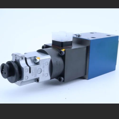
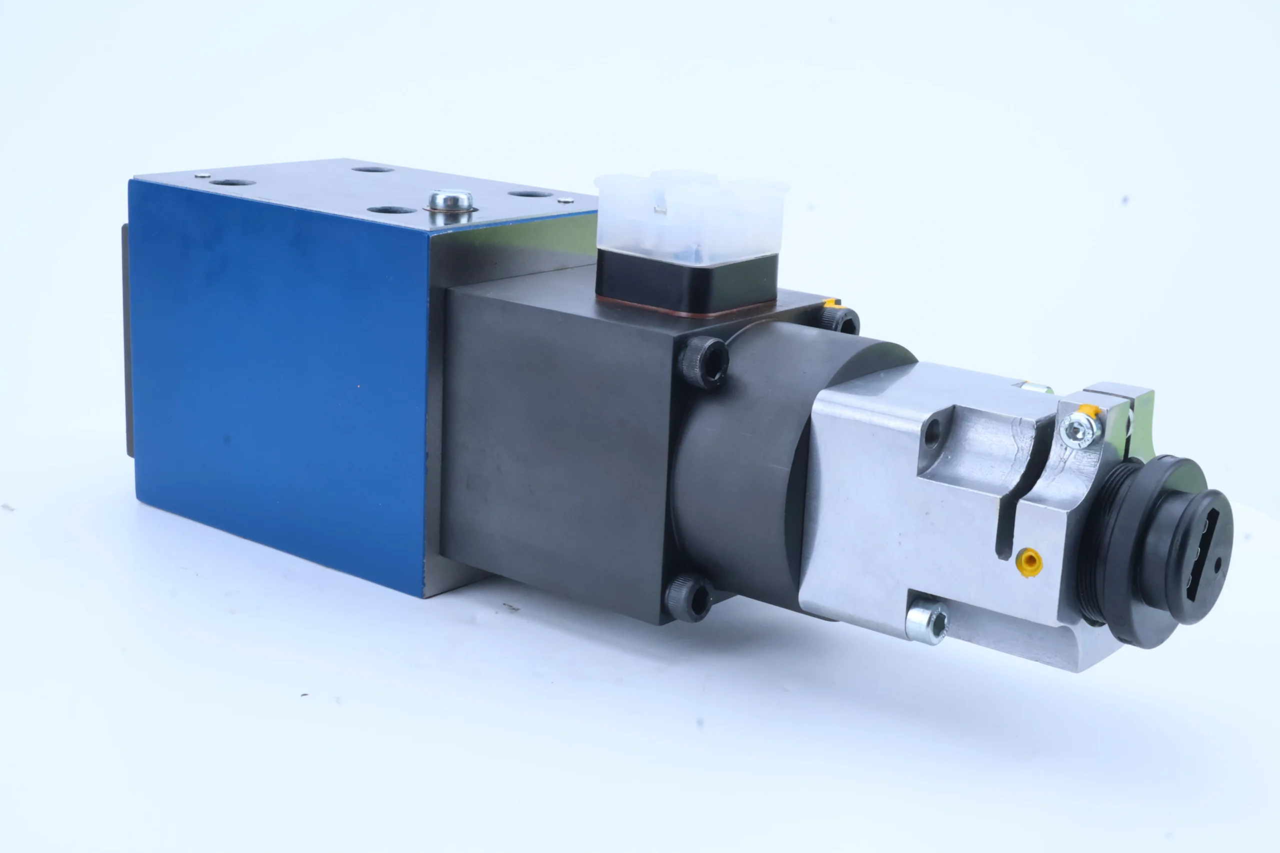
– Valve type: Electro-hydraulic proportional directional control valve, three-position four-way structure, with a neutral function of O-type (closed), suitable for medium and high-pressure hydraulic circuits. It achieves precise flow/pressure regulation through electro-proportional signals, providing smooth action control for the actuator.
– Pressure and flow parameters: Rated working pressure 32 MPa, maximum allowable pressure 35 MPa (short-term ≤5 seconds); Rated diameter: 10 mm, rated flow rate: 30 L/min, maximum flow rate: 40 L/min (when pressure drop ≤0.6 MPa).
– Control and response parameters: The control mode is DC proportional electromagnet control (G24), with a rated control voltage of DC 24V (allowable fluctuation ±10%). The control current is 400-800 mA, the reversing response time is ≤0.15 seconds, with valve core position feedback (Z4), and the control accuracy is ±1%.
– Operating characteristics: Working oil temperature range: -20℃ to 100℃; Leakage ≤3 mL/min (at rated pressure); The proportional electromagnet has a protection grade of IP65 and a rated working condition fault-free life of ≥1 million commutations.
2. Structure and connection parameters
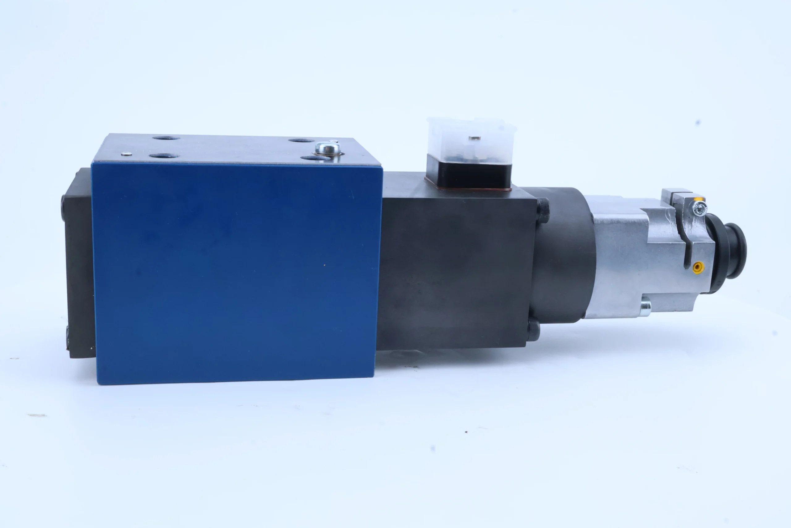
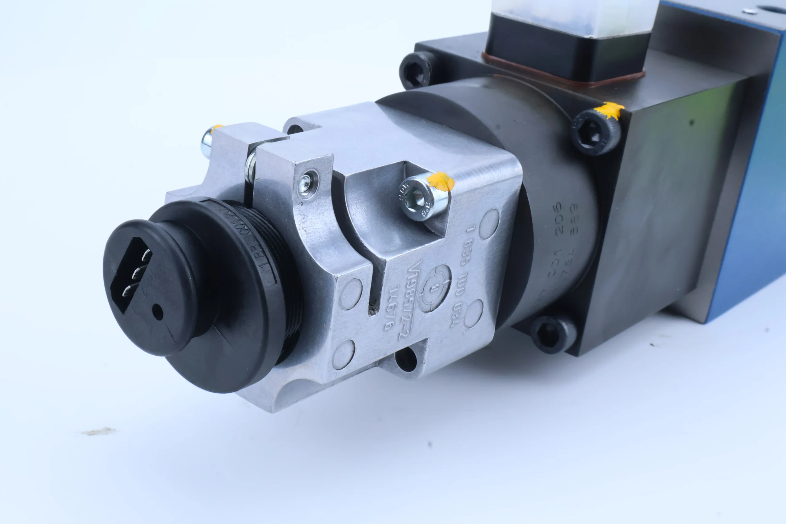
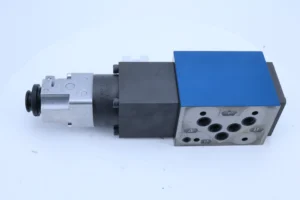
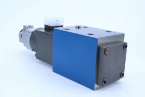
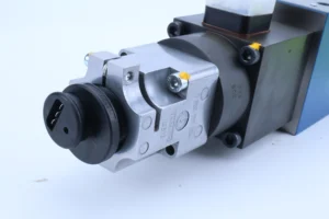
– Structural type: Spool valve core structure, integrating proportional electromagnet, reset spring, valve core, valve sleeve, position sensor and built-in buffer valve; It adopts a plate installation design. The middle O-shaped machine can achieve load pressure holding and is equipped with a manual emergency adjustment knob.
– Core material: The valve core is made of stainless steel 304 (quenched and tempered, hardness HRC38-42); The valve sleeve is made of alloy cast iron QT500-7 (aged treatment). The core of the proportional electromagnet is made of electrical pure iron DT4. The sealing part is a high-pressure resistant fluororubber combination (temperature resistance ≤120℃).
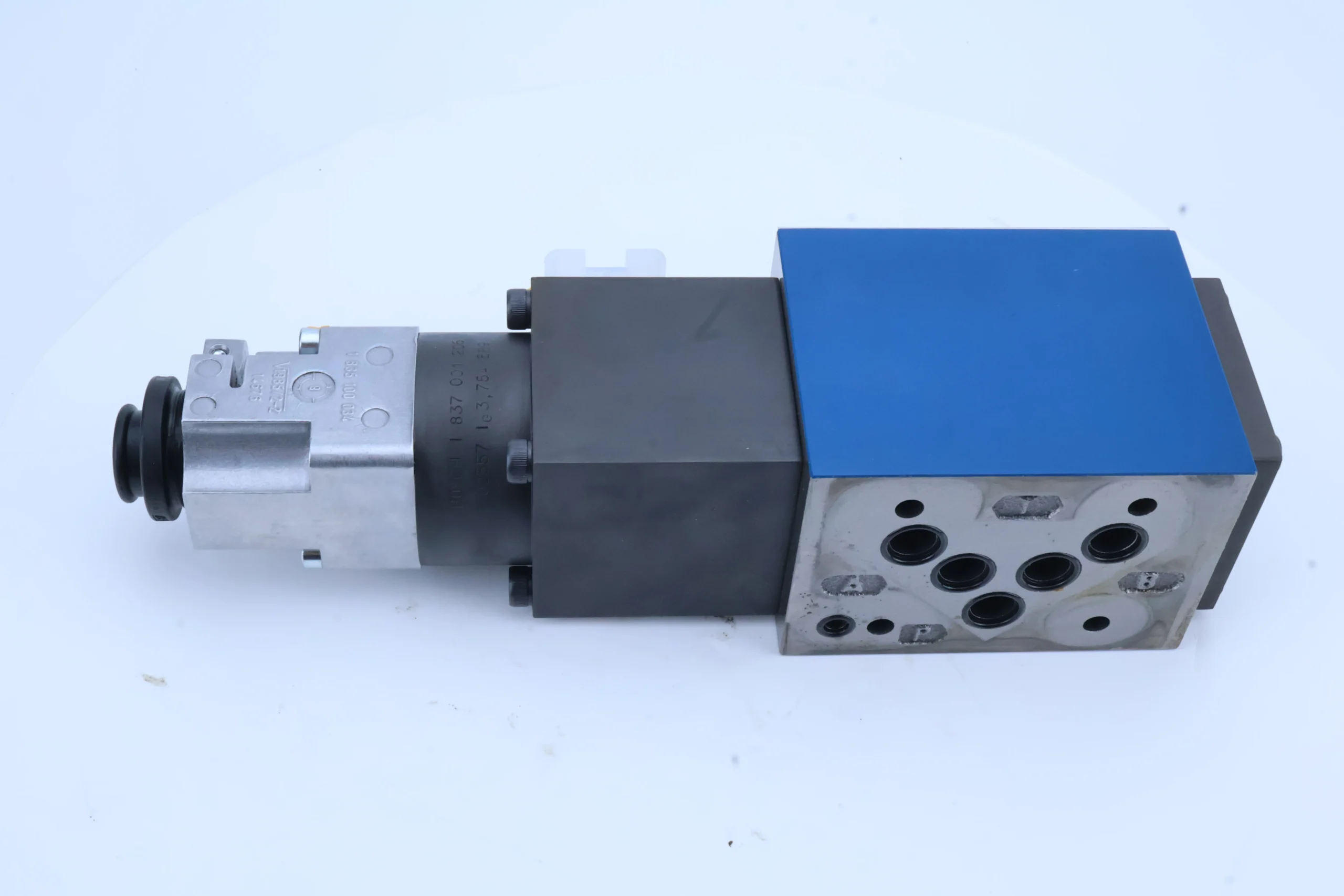
– Connection specifications: The oil inlet (P), return oil port (T), and working oil port (A/B) are all G3/4 threaded connections. The center distance of the installation holes is arranged in accordance with international standards (63×100 mm). The weight of the valve body is approximately 4.5 kg, and its external dimensions (length × width × height) ≈220×100×140 mm.
3. Medium and Environmental requirements
– Medium requirements: Compatible with L-HM 32/46/68 anti-wear hydraulic oil, allowing medium viscosity of 10-400 mm²/s; Moisture content ≤0.05%. It is strictly prohibited to use media containing solid particles (particle size > 5 μm) or corrosive media.
– Cleanliness standard: The oil cleanliness must reach ISO 4406 15/12 grade. A 5 μm fine filter must be installed before the valve. The filter should be replaced in time when the pressure difference of the filter is greater than 0.1 MPa.
– Environmental parameters: Operating environment temperature -20℃ to 80℃, relative humidity ≤95% (short-term condensation is allowed); With a protection grade of IP65, it is suitable for scenarios such as construction machinery, precision industrial hydraulic stations, and automated production lines.Ii. Working Principle
This valve is an electro-hydraulic proportional directional control valve. Its core achieves controllable regulation of the oil circuit flow and direction through the mechanism of “electro-proportional signal conversion – hydraulic amplification – precise positioning of the valve core”. The specific process is as follows:
1. Normal (no signal) state
When there is no electrical signal input, the valve core is in the neutral position under the force of the reset springs at both ends, and the O-type machine can close the oil inlet (P), return oil port (T), and working oil port (A/B). At this time, the actuator has no oil inflow or outflow and remains stationary under the load, achieving median pressure holding.
2. Reversing and adjusting status
When a DC 24V electrical signal (adjustable from 400 to 800 mA) is applied to the proportional electromagnet, the electromagnet generates an electromagnetic force proportional to the current, which drives the pilot valve core to move, controlling the high-pressure oil to enter the control chamber at one end of the main valve core, and driving the main valve core to move axially over the force of the reset spring, thus achieving oil circuit switching. The oil inlet (P) is connected to the working oil port (A), and the working oil port (B) is connected to the return oil port (T), with the actuator extending out. As the current increases, the displacement of the valve core increases, the opening degree of the oil port increases, and the flow rate increases proportionally accordingly.
3. Feedback and Closed-loop Control
The valve core is equipped with an internal position sensor (Z4), which detects the displacement of the valve core in real time and feeds the signal back to the controller to form a closed-loop control. If there is a deviation between the actual displacement and the target displacement, the controller automatically adjusts the input current to ensure the precise positioning of the valve core, achieving stable output of flow or pressure and meeting the requirements of high-precision operations.
Iii. Product Features and Advantages
– Precise proportional control: Closed-loop control with valve core position feedback, flow regulation accuracy ±1%, pressure control accuracy ± 0.2MPa, capable of stepless adjustment of the actuator’s speed or force, suitable for high-precision scenarios such as precision forming and automated assembly.
– High pressure and large flow rate compatibility: With a rated pressure of 32 MPa and a diameter of 10 mm, and a stable flow rate of 30 L/min, it can drive the actuator of 10-30 ton equipment, balancing high pressure resistance and flow rate regulation flexibility, making it suitable for medium and heavy-duty precision operations.
– Fast and stable response: The reversing response time is ≤0.15 seconds, and the flow step response has no overshoot. It can achieve high-frequency smooth switching of the actuator (such as industrial grasping by hydraulic manipulators), and the operation efficiency is 40% higher than that of ordinary reversing valves.
– Reliable and durable: The valve core and valve sleeve are precisely ground (fit clearance ≤ 0.005mm), and the proportional electromagnet is treated with an anti-corrosion coating. With an IP65 protection level, it can be adapted to dusty and humid working conditions. The fault-free commutation life under rated working conditions is ≥1 million times.
– Convenient integrated operation and maintenance: The plate installation design is compatible with the layout of standardized hydraulic stations, saving 20% of the installation space compared to cartridge valves. It is equipped with a manual emergency knob, which can be manually adjusted in case of power failure. The position feedback signal can be directly connected to the PLC, facilitating the integration of system automation.
Iv. Usage Functions and Purposes
1. Core usage functions
– Proportional flow control: By adjusting the input current to change the valve core opening proportionally, it enables stepless speed regulation of the actuator (such as the pressing speed of the hydraulic press, the extension and retraction speed of the mechanical hand), adapting to the multi-stage speed requirements of “fast advance – industrial advance – fast retreat”.
– Direction and pressure holding control: Switching the input direction of the electrical signal enables the actuator to change direction. The neutral O-type machine can achieve long-term pressure holding of the load (pressure holding accuracy ±0.3 MPa), such as pressure holding during hydraulic fixture clamping and pressure holding during injection molding machine mold closing.
– Closed-loop pressure control: In conjunction with pressure sensors, a pressure closed loop is formed, and precise control of output pressure is achieved through proportional regulation (such as the regulation of pressing force in forging equipment), with pressure fluctuation ≤0.2 MPa.
2. Main application fields
In the field of construction machinery: 10-30 ton crawler excavators (precise control circuits for boom/bucket arm), 20-30 ton wheel loaders (lifting speed regulation circuits), 80-150 ton truck cranes (luffing smooth control circuits), suitable for fine operation scenarios.
In the field of industrial equipment: 500-1000 ton hydraulic presses (pressing speed and pressure control circuits), large injection molding machines (precision circuits for mold closing and ejection), and industrial hydraulic manipulators for automated production lines (circuits for grasping and assembly), suitable for precision manufacturing operations.
– Specialized fields: Small mine tunnel boring machines (propulsion speed regulation circuits), 10-30 ton cranes in ports (smooth lifting control circuits), hydraulic systems for medical equipment (high-precision motion control), suitable for operations with high requirements for smoothness.
V. Applicable Machines and Scenarios
1. Adapt to the core machine
– Construction machinery: 10-30 ton crawler excavators, 20-30 ton wheel loaders, 80-150 ton truck cranes, small hydraulic crushing stations.
– Industrial equipment: 500-1000 ton hydraulic presses, 600-1000 ton injection molding machines, automated hydraulic manipulators, hydraulic systems for medium-sized CNC lathes.
– Special equipment: Small mine tunnel boring machines, 10-30 ton gantry cranes for ports, hydraulic equipment for medical devices, precision forging machines.
2. Typical application scenarios
– Precision forming scenario of hydraulic press: It is used in the main cylinder circuit of 800-ton hydraulic press. Through proportional control, it realizes the full process automation of rapid advance (40 L/min), working advance (5-30 L/min stepless adjustment), holding pressure (32 MPa, accuracy ±0.2 MPa), and rapid retreat. It is suitable for precision stamping of automotive parts, and the product qualification rate is increased by 15%.
– Fine operation scenarios of excavators: As a control valve for the bucket arm of a 20-ton excavator, it regulates the extension and retraction speed of the bucket arm (5-20 cm/s) through proportional signals, and achieves precise positioning of the bucket arm in combination with position feedback. It is suitable for fine operations such as pipeline laying and slope shaping in municipal engineering, with an operation error of ≤5 mm.
– Mechanical hand assembly scenario: Equipped with an automated hydraulic mechanical hand grasping circuit, it can switch between grasping, translation and placement actions in 0.15 seconds with rapid reversing. The flow ratio adjustment ensures a stable grasping force (±5%), making it suitable for precision assembly of electronic components, automotive parts, etc. The average daily operation frequency can reach over 10,000 times.
Six. Similar models
1. Alternative models of the same series
-4WRP08 EA32S-1X/G24Z4/M: A small-bore model of the same structure, with a bore of 8mm, a rated flow rate of 20L /min, and consistent pressure parameters. It is suitable for 5-10 ton class light equipment (such as small hydraulic manipulators), and the cost is 25% lower than that of the original model.
-4WRP 12 EA32S-1X/G24Z4/M: Large-diameter model of the same series, with a diameter of 12mm, a rated flow rate of 45L /min, and the same pressure parameters. It is suitable for heavy equipment of 30-50 tons (such as the main circuit of a 30-ton excavator), but the cost is 30% higher than that of the original model.
2. Cross-series alternative models
-4WRP 10 EA25S-1X/G24Z4/M: Low-pressure compatible model, rated pressure 25 MPa, consistent diameter and flow parameters, suitable for medium and low-pressure precision systems (such as medical devices), cost 15% lower than the original model.
-4WRP 10 EA32S-1X/G110Z4/M: AC control model, control voltage AC 110V, structure and performance parameters consistent, suitable for fixed equipment without DC power supply (such as workshop hydraulic stations), cost the same as the original model.
-4WRP 10 EA32S-1X/G24Z5/M: High-precision feedback model, featuring magnetostrictive position sensors, with control accuracy improved to ±0.5%, suitable for ultra-high-precision operations (such as aviation parts processing), and the cost is 40% higher than that of the original model.
Vii. Precautions for Use
1. Medium management
At normal temperature, L-HM 46/68 anti-wear hydraulic oil should be selected. At low temperature (below -10℃), L-HM 32 should be selected. It is strictly prohibited to mix different grades or deteriorated oils. Before the installation of the new valve, the pipeline should be flushed with clean oil for ≥30 minutes to ensure that the oil cleanliness meets ISO 4406 15/12 grade and avoid impurities getting stuck in the valve core.
– Check the pressure difference of the filter before the valve weekly (replace the filter element when it exceeds 0.1 MPa), test the moisture content of the oil monthly (≤0.05%), and take samples to test the cleanliness quarterly. If emulsification, discoloration of the oil or jamming of the valve core adjustment is found, immediately stop the machine, change the oil and disassemble and clean the valve body.
2. Installation and commissioning
When installing, confirm the oil port markings (P for oil inlet, T for oil return, A/B for working oil ports), and it is strictly forbidden to connect them in reverse. When installing the plate type, the bolts should be evenly tightened with a torque of 200 N·m to ensure there is no leakage at the sealing surface. The terminal blocks of the proportional electromagnet need to be tightened and properly insulated for protection.
Before debugging, manually rotate the emergency knob 2 to 3 turns to confirm there is no jamming. Connect the DC 24V control power supply, input different currents such as 500mA and 700mA through the controller, test the valve core displacement feedback value and flow output, and ensure that the linearity error is ≤1%. Reverse the direction 10 times without load to check the smoothness of the operation.
The valve body should reserve a heat dissipation space of ≥ 80mm. For outdoor installation, a rain cover should be added (maintaining IP65 protection). The position feedback signal line needs to be wired separately to avoid interference with strong current lines. When debugging the system pressure, gradually increase the pressure to the rated pressure to avoid sudden increase that may impact the valve core.
3. Operation and Maintenance
During operation, real-time monitoring of the valve body temperature (normal ≤60℃, maximum ≤80℃), leakage and feedback signals is carried out. If the temperature rises sharply by more than 15℃, the leakage is greater than 3 mL/min, or the feedback signal fluctuates by more than 2%, stop the machine immediately for inspection, with a focus on checking for oil contamination, electromagnet failure, or valve core wear.
Regular maintenance every 2000 hours: Disassemble the valve body to clean the valve core and valve sleeve, and check the fit clearance (replace the valve core when it is greater than 0.01mm). Replace the sealing parts and filter elements, recalibrate the position feedback zero point and gain, and ensure that the control accuracy meets the standards.
It is strictly prohibited to operate under long-term overpressure (> 35 MPa) or overflow (> 40 L/min). Avoid keeping the control current above 800 mA at full load for a long time to prevent the electromagnet from overheating and burning out. Before power-off maintenance, the system pressure should be released to prevent injury from oil spraying.
4. Storage protection
When stored for a long time, use a special plug to seal the oil port, inject anti-rust oil into the valve body, and apply anti-rust grease to the surface of the proportional electromagnet. Store in a dry warehouse with a temperature range of 0-40℃ and a humidity of no more than 60%. Avoid direct sunlight, heavy object compression and corrosive gas erosion. Manually adjust the emergency knob once every three months.
Before being put into use after being idle for more than 12 months, disassemble and clean the inner cavity of the valve body, and replace the sealing parts. Use a multimeter to test the resistance of the electromagnet (normally 50-80 Ω). After confirming there is no short circuit, connect it to the test system and run it at low speed for 1 hour. After verifying that all performance indicators meet the standards, connect it to the main system.


