
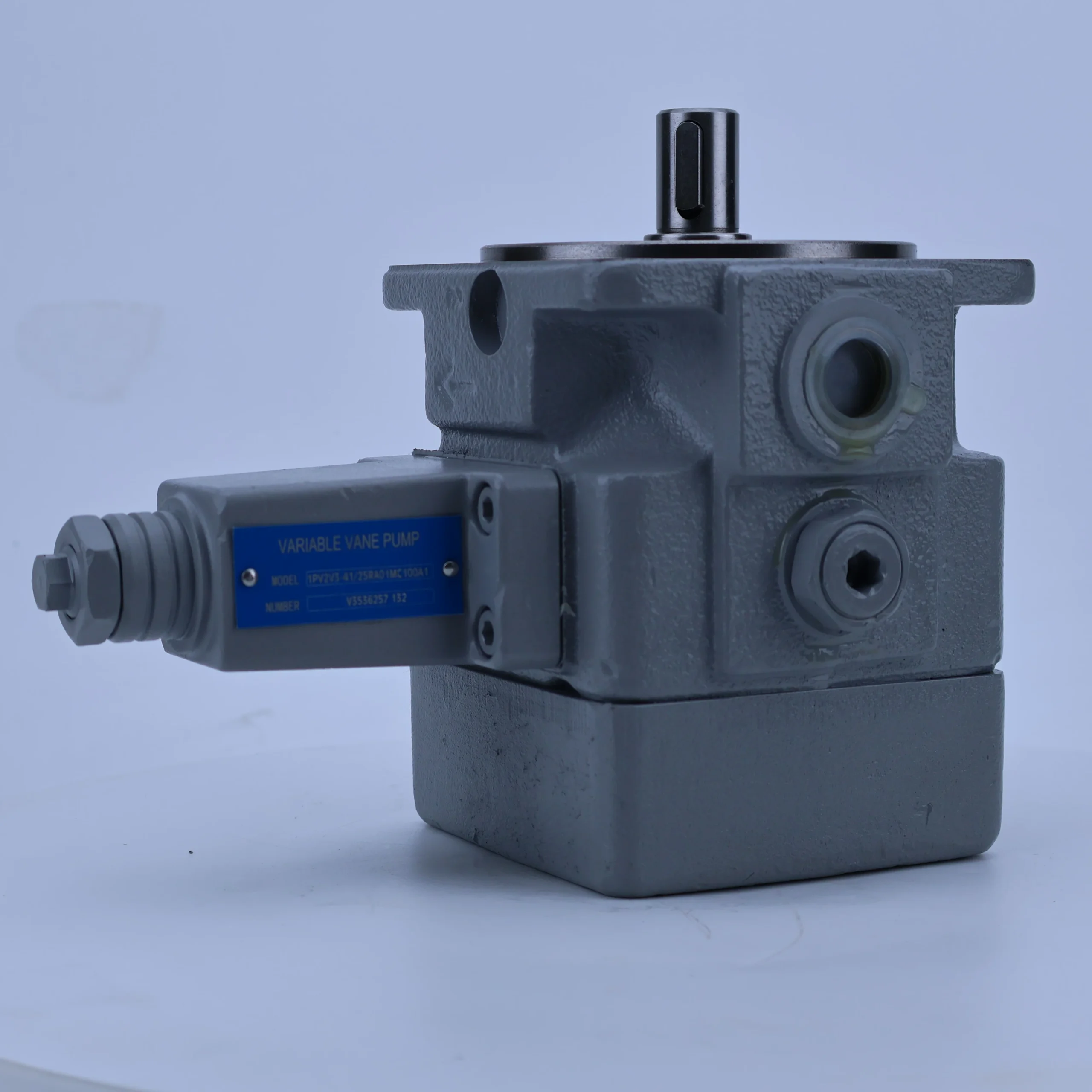

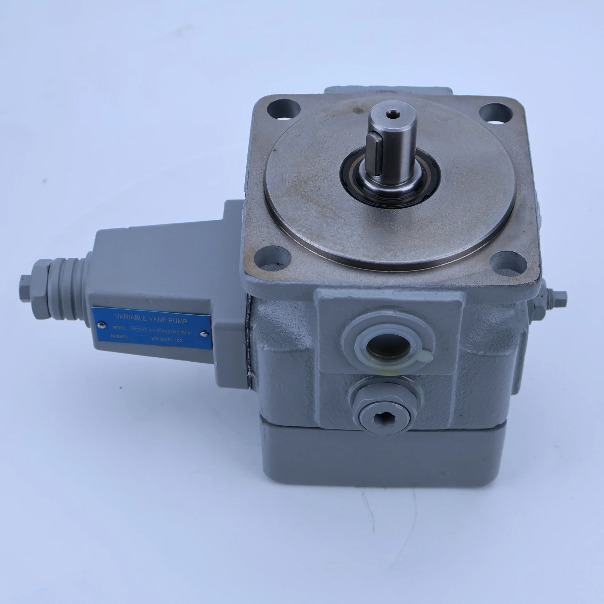


Hydraulic Pump 1PV2V3 1PV6V3 1PV2V4 1PV2V5 1PV6V3-30 Series 1PV6V3-30/63RA08MC40A1 High Pressure Hydraulic Vane Pump OEM
1. Basic performance parameters- Pump body type: Double-coupled single-acting variable vane pump, integrating double independent pressure compensation variable mechanisms and composite relief valves, supporting unidirectional rotation, suitable for medium and high-pressure high-flow hydraulic systems
– Displacement and pressure parameters: Variable displacement range 30-63 cc/rev (model “30/63” corresponds to minimum/maximum displacement); The rated working pressure is 160 bar, the maximum allowable pressure is 210 bar (short-term ≤10 seconds), the back pressure of the return oil is ≤3 bar, and the pressure difference between the two circuits is ≤2 bar
– Speed and flow parameters: Rated speed 3000 rpm, maximum speed 3600 rpm (short time ≤5 minutes), minimum stable speed 600 rpm; The maximum output flow at the rated speed is 189 L/min (63 cc/rev×3000 rpm÷1000), and the minimum flow is 90 L/min (30 cc/rev×3000 rpm÷1000).
– Efficiency parameters: Rated working condition volumetric efficiency ≥92%, total efficiency ≥86%; The pressure compensation response time of the single pump core is ≤50 ms, and the flow regulation accuracy of the dual circuits is ±2%
2. Structure and connection parameters
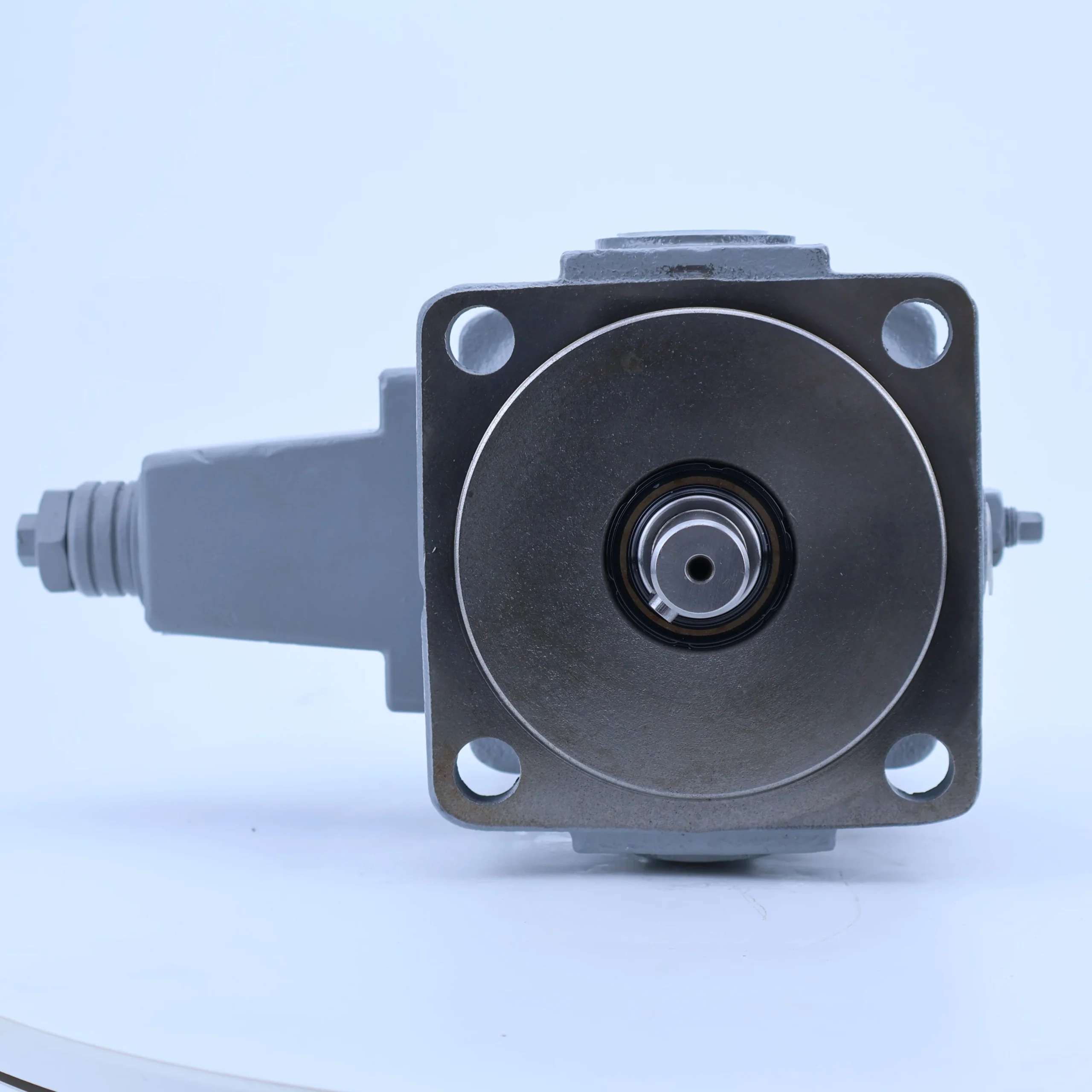
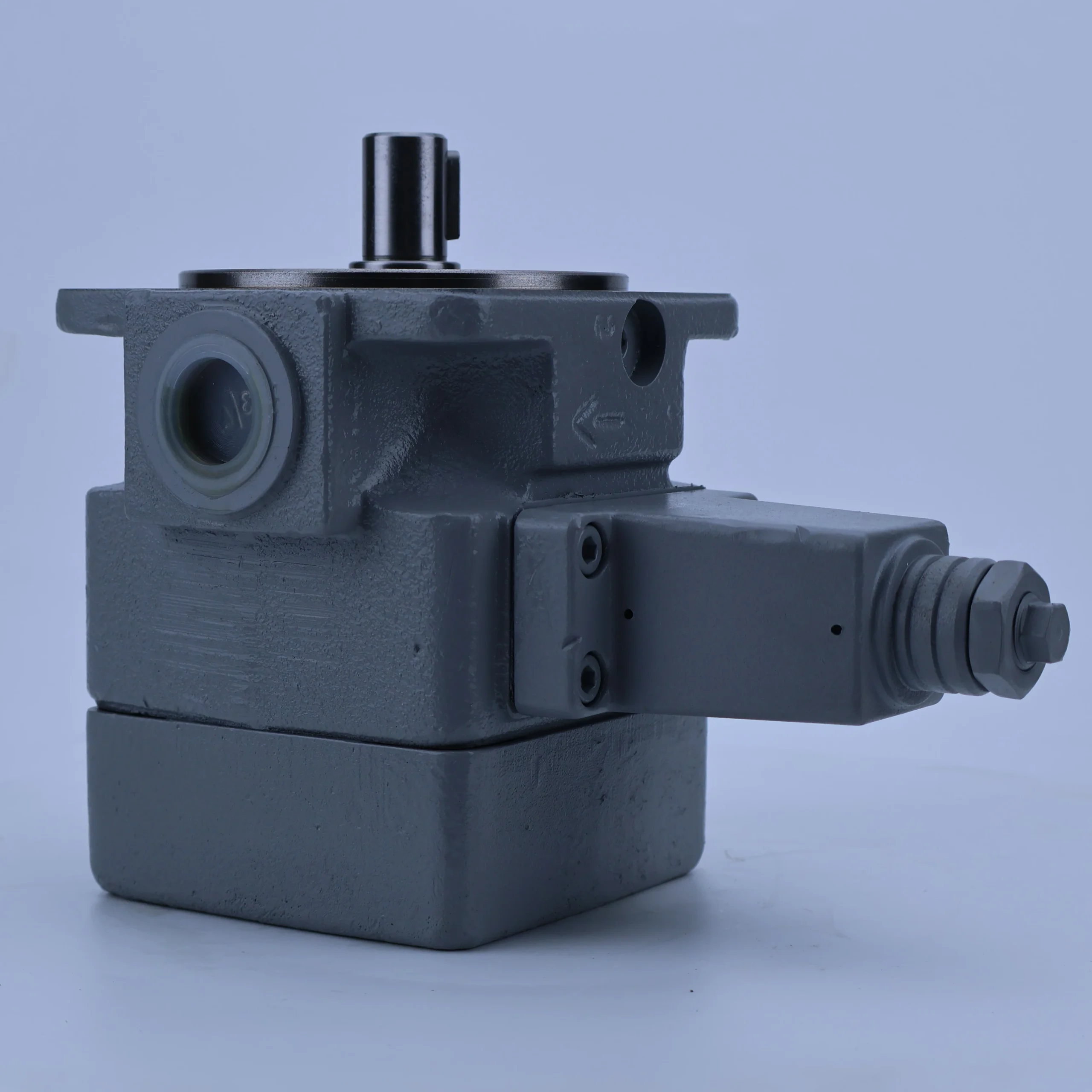
– Structural type: Cast iron one-piece formed pump body, surface phosphating anti-rust treatment; Alloy steel rotor (hardness HRC58-62), copper-based alloy blades (containing self-lubricating components), wear-resistant cast iron stator, double-end mechanical seal + lip seal combination; The two pump cores are arranged in parallel, sharing the input shaft and integrating an internal oil passage to achieve independent oil return
– Installation and connection specifications: Flange installation (compatible with ISO 3019-1 standard, “RA08” corresponds to installation positioning); Oil port threads: Common oil suction port G2, dual independent oil outlet ports G1 1/4 each, dual control oil port G1/8 each; The output shaft is connected by involute splines (10-tooth / 12-tooth options are available). The overall weight is approximately 28 kg, and the external dimensions (length × width × height) ≈420×280×220 mm
– Protection grade: IP65, suitable for dusty and humid industrial and medium to large construction machinery environments
3. Medium and Environmental requirements
– Medium requirements: Compatible with L-HM 32/46/68 anti-wear hydraulic oil, allowable medium viscosity range 17-37 mm²/s, moisture content ≤0.02%, solid particle size ≤10 μm
– Environmental parameters: Operating environment temperature -20℃ to 80℃, relative humidity ≤95%; The cleanliness of the oil should reach ISO 4406 14/11 grade
– Filtration requirements: A filter screen of ≥100 mesh should be installed on the oil suction side, and the filtration accuracy on the oil return side should be ≤25 μm. It is recommended to install a high-pressure filter (accuracy ≤10 μm) on each of the two oil outlets.
Ii. Working Principle
This pump is a double-pump single-acting variable vane pump. Its core realizes the conversion of mechanical energy and hydraulic energy and the adaptive regulation of dual-loop flow through the mechanism of “volume change of dual pump cores + independent pressure feedback regulation”. The specific process is as follows:
1. Core mechanism of power transformation
The motor drives the input shaft to synchronously rotate the rotors of the two pump cores. Under the action of centrifugal force and root pressure oil, the blades inside each pump core closely adhere to the inner surface of the stator. The rotor and stator are eccentrically arranged, and adjacent blades, rotors, stators and distribution plates form independent sealed working chambers. When the rotor rotates, the working chamber volume of the oil suction zone of each pump core increases to form a vacuum, which sucks oil through the common oil suction port and fills the tooth grooves of the two pump cores respectively. The volume of the working chamber in the oil pressure area is reduced, squeezing the oil to generate pressure. The oil is guided to the dual oil outlets through their respective independent distribution plates for discharge, achieving independent oil supply in two circuits. When an extremely large flow rate is required, the total displacement oil supply can be achieved by converging the two oil outlets through external pipelines.
2. Variable regulation and protection mechanism
Each of the two pump cores is equipped with an independent pressure-compensating variable mechanism, which is combined with a compound relief valve. When the pressure in a certain circuit rises to the set value, the corresponding variable piston pushes the stator to change the eccentricity. The displacement of this pump core decreases from 63 cc/rev to 30 cc/rev, achieving an independent adaptive regulation of “pressure increase in a single circuit → flow decrease in a single circuit”. When the pressure in any circuit exceeds the maximum allowable value of 210 bar, the corresponding relief valve group is fully opened to unload, guiding the oil back to the suction chamber to prevent the pump body from overloading. The distribution plate adopts a pressure self-compensation design to reduce axial leakage and maintain the high volumetric efficiency of the dual circuits.
Iii. Product Features and Advantages
– Dual independent regulation: The dual pump cores share the input shaft but operate independently, enabling wide-range regulation of 30-63cc /rev in a single circuit. The flow difference between the two circuits is ≤2%, making it suitable for the differentiated load requirements of multiple actuators. It supports independent fuel supply (90-189 L/min single channel) or combined fuel supply (180-378 L/min total flow), and its scene adaptability is 100% higher than that of a single pump
– Energy-saving and efficient operation: The dual independent pressure compensation mechanism can adjust the displacement respectively according to the load of the dual circuits, saving 25% to 35% energy compared with two independent single pumps. The flow regulation response time is ≤50 ms. There is no impact during flow switching when the load fluctuates, making it suitable for high-frequency variable load scenarios
– High wear resistance and long service life: Alloy steel rotor nitrided treatment, copper-based self-lubricating blades combined with precisely honed stator, blade wear ≤ 0.05mm per 10,000 hours; The static leakage of the dual mechanical seal combination is ≤2 mL/min, and the fault-free operating life under rated conditions is ≥ 15,000 hours
– Low noise and high integration: The modified blade chamfer and the symmetrical arrangement of the dual pump cores design ensure that the operating noise at 1 meter is ≤75 dB, which is 5 dB lower than that of the conventional double vane pump. The integration of a bivariable mechanism and a composite relief valve reduces the volume by 40% compared to two independent single pumps and the number of external components by 60%
Iv. Usage Functions and Purposes
1. Core usage functions
Dual-loop variable flow oil supply: It provides two independently adjustable pressure and flow paths for complex hydraulic systems, driving two actuating elements with differentiated loads, with a single-loop flow accuracy of ±2%
– Load adaptive regulation: The dual independent variable mechanism automatically matches the displacement based on the load pressure of each circuit to avoid redundant energy consumption due to flow. The compound relief valve provides dual-loop independent overload protection, replacing external valve groups to simplify the system
– Flexible flow switching: Supports three operation modes: single-loop independent operation, dual-loop synchronous operation, and dual-loop combined operation, meeting the flow requirements of different working conditions. The switching response time is ≤0.1 seconds
2. Main uses
As a core power component of medium and high-pressure, high-flow complex hydraulic systems, it connects high-power motors with multiple actuating elements, providing energy-saving power for multi-action coordination and load differentiation scenarios of various industrial machinery and large-scale construction machinery. It is a key power source for large production lines and heavy equipment.
V. Applicable Machines and Scenarios
1. Adapt to the core machine
– Industrial machinery: 500-1000 ton injection molding machines, large die-casting machines, CNC machining center tool turret + worktable systems, heavy-duty hydraulic presses
– Construction machinery: main and auxiliary action systems for 10-20 ton excavators, dual-circuit lifting and steering systems for loaders, luffing and lifting mechanisms for hydraulic crawler cranes
– Special equipment: large-scale automated assembly production lines, multi-winch systems for ship decks, roll adjustment mechanisms for metallurgical equipment, heavy-duty hydraulic test benches
2. Typical application scenarios
– Large injection molding machine forming scenario: Equipped with an 800-ton injection molding machine, with dual circuits respectively driving the mold closing and injection mechanisms; During the mold closing stage, both pump cores are adjusted to 63 cc/rev for combined oil supply (378 L/min) to achieve rapid mold closing (time ≤3 seconds). During the injection stage, the mold closing circuit is reduced to 30 cc/rev for pressure holding, and the injection circuit maintains 63 cc/rev for material supply. The energy consumption per shift is reduced by 30% compared to two single pumps
– Dual-action scenario for excavators: As the power source for a 15-ton excavator, it uses dual circuits to drive the boom and the bucket cylinder respectively. When performing compound actions, the boom circuit has a displacement of 40 cc/rev at a pressure of 160 bar and the boom circuit has a displacement of 50 cc/rev at a pressure of 140 bar. The dual circuits are independently regulated to achieve smooth compound actions, with an action response time of no more than 0.2 seconds
– Automated production line scenario: Drive the dual-station press-fitting mechanism of a large automotive parts assembly line. The dual circuits respectively control the two press-fitting heads. The displacement is 30-63cc /rev, suitable for different press-fitting force requirements of 5-30kN. The pressure stability error is ≤1%, and the press-fitting depth accuracy is ≤ 0.05mm, meeting the requirements of batch precision assembly
Six. Similar models
1. Different models of the same series displacement
-1PV6V3-25/50RA08MC40A1: Minimum/maximum displacement 25/50 cc/rev, rated flow 75-150 L/min, rated pressure 160 bar, suitable for medium-sized dual-loop systems (such as 500-ton injection molding machines, 10-ton excavators), 25% smaller in size, approximately 22 kg in weight
-1PV6V3-35/75RA08MC40A1: Minimum/maximum displacement 35/75cc /rev, rated flow 105-225 L/min, maximum pressure 210 bar, suitable for super-large systems (such as 1000-ton die-casting machines, 20-ton cranes), total flow increased by 20%
2. Models with the same displacement but different functions
-1PV6V3-30/63RA08MC40A1-M: Manual synchronous variable adjustment mechanism model, suitable for dual-loop load consistent scenarios, with a simple structure and 20% lower cost
-1PV6V3-30/63RA08MC40A1-E: An electro-hydraulic proportional independent control model, supporting PLC remote adjustment of dual-loop displacement and pressure, with a control accuracy of ±0.5%, suitable for fully automatic production lines, but with a 50% higher cost
-1PV6V3-30/63LA08MC40A1: Left-rotating installation model, suitable for equipment with limited motor rotation direction. The dual oil outlet directions are reversed, and other performances are the same
Vii. Precautions for Use
Installation and commissioning
When installing, ensure that the coaxiality error between the input shaft and the motor shaft is ≤ 0.1mm. Use high-strength elastic couplings for connection. Radial force (≥ 100N) must not be directly applied to the pump shaft to avoid eccentric offset and asynchrony of the two pump cores
The oil suction pipeline should be short, straight and thick (length ≤2 meters, diameter ≥50 mm), the distance between the oil suction port and the bottom of the oil tank should be ≥200 mm, and the filtration accuracy of the filter should be ≥100 mesh. The pipeline connection is fastened with double bolts. The sealing gasket is made of oil-resistant fluororubber to ensure no air leakage. A vacuum gauge (vacuum degree ≤0.02 MPa) is installed on the oil suction side.
Before the first start-up, hydraulic oil should be filled into the dual pump core cavity. Manually turn the machine 5 to 6 times to confirm that the blades of the dual pump core can extend and contract flexibly. When starting, first open the oil suction valve and run it no-load at low pressure (50 bar) and low speed (1000 rpm) for 30 minutes. Gradually increase it to the rated parameters and calibrate the dual-circuit pressure-displacement curve at the same time (ensuring that the error of the dual-circuit is ≤2%).
– Reverse rotation operation is prohibited; For outdoor installation, a rain and dust-proof protective cover should be added. A heat dissipation space of ≥ 300mm should be reserved around the pump body. When the ambient temperature exceeds 40℃, forced water cooling for heat dissipation is required
2. Operation and Maintenance
During operation, the temperature of the dual pump cores (normal ≤80℃, maximum ≤90℃), pressure fluctuations and noise of the dual circuits are monitored daily. If the temperature rises sharply by more than 10℃, the pressure fluctuates by more than 5 bar or the noise exceeds 85 dB, stop the machine immediately for inspection. Focus on checking the contamination level of the oil (once every two months), blade wear or jamming of the variable mechanism
– Regular maintenance cycle: Replace the hydraulic oil and the three-stage filter every 5,000 hours; Disassemble and inspect every 12,000 hours. Replace when the blade thickness wear is ≥ 0.1mm or the inner surface of the stator is scratched. At the same time, replace the sealing parts and the double-variable mechanism spring. Calibrate the dual-loop pressure setting value every 3,000 hours
No-oil idling is strictly prohibited (idling for more than 3 seconds can easily cause scratches on the blades and stator). It is prohibited for the dual circuit to operate at full load with the minimum displacement (30 cc/rev) for a long time (single operation ≤2 hours). Before the system is shut down, it needs to be reduced to low pressure and run no-load for 5 minutes. After the oil temperature is ≤60℃, the oil source should be cut off
3. Storage and Protection
When stored for a long time, all oil ports should be sealed with special plugs. Anti-rust oil (about 200 mL) should be injected into the double pump core cavity, and lithium-based grease should be applied to the splines of the input shaft. Store in a dry warehouse with a temperature ranging from 0 to 45℃ and a humidity of no more than 60%. Avoid direct sunlight and heavy object compression. Manually turn the machine once every two months
Before putting the pump into use after being idle for more than 12 months, thoroughly clean the pump cavity and pipelines, replace all seals and hydraulic oil, and regrind the mating surfaces of the double distribution plates and the stator. Run the low-speed no-load test for 20 minutes to detect the variable response and leakage of the dual circuits (a single circuit ≤2 mL/min is normal). Only after meeting the standards can it be connected to the system


