
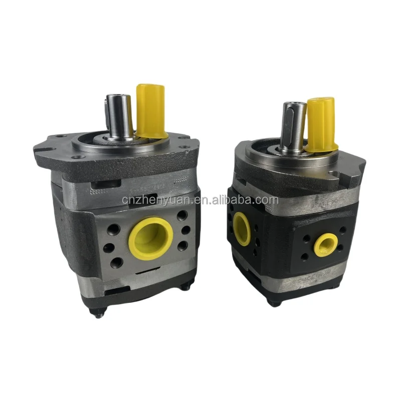


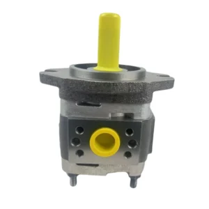


IPV IPVP IPC IPV3 IPV4 IPV5 IPV6 IPV7 IPVP4 IPVP5 IPVP6 High Pressure Internal Hydraulic Gear Pump IPVP5-40-101 Oil Pump
Basic specifications
Type: Internal Meshing variable gear pump. “IPVP” indicates the series code, “5” indicates the specification grade, “40” indicates the nominal displacement of 40 m³/h (667 L/min), and “101” indicates the pressure grade of 101 bar (10.1 MPa).
Nominal displacement: 40 m³/h (667 L/min), theoretical flow rate is directly proportional to rotational speed, variable range 0-100%
Rated pressure: 101 bar (10.1 MPa), upper limit of continuous working pressure, short-term peak up to 120 bar
Rated speed: 1800 r/min. It is recommended to operate at full power. The maximum speed can reach 2000 r/min (for short-term operation)
Rotation direction: Right rotation (clockwise rotation when viewed from the shaft end), and a left rotation model is also available
Medium temperature: -10℃ to +60℃. The recommended working temperature is 20-50℃ to avoid a decrease in oil viscosity due to high temperatures
Weight: Approximately 40 kg (excluding accessories), compact structure, easy to install
Working parameters
Volumetric efficiency: ≥92% (under rated conditions), ensuring efficient energy conversion
Overall efficiency: ≥85%, with high comprehensive energy utilization efficiency
Applicable media: hydraulic oil, lubricating oil, fuel oil, etc. Viscosity range: 10-300 mm²/s, optimal working viscosity: 20-60 mm²/s
Noise level: <66 dB (DIN45 635 standard), smooth and quiet operation, improving the working environment
Oil cleanliness: ISO 4406 19/16 grade. It is recommended to install a 20μm filter at the oil inlet to protect the precision componentsIi. Working Principle
Working mechanism of internal meshing variable gear pump
Core structure
It is composed of a pump body, an internal gear (driving gear), an external gear (driven gear), a crescent-shaped diaphragm and a movable eccentric shaft
The internal gear and the external gear form two sealed chambers inside the pump body, which are separated by crescent plates
The internal gear has one more tooth than the external gear to ensure good meshing and sealing
The eccentric shaft can move radially to change the center distance (eccentricity) between the internal gear and the external gear.
Oil suction and discharge process
Oil suction stage: The transmission shaft drives the internal gear to rotate, and the internal gear and the external gear gradually disengage from meshing on the oil suction side
The increase in the volume between the teeth creates a local vacuum (negative pressure), and the liquid in the oil tank is sucked into the pump chamber under the action of atmospheric pressure
The liquid fills the gaps between the teeth and moves towards the oil discharge side as the gear rotates
Oil discharge stage: When the gear rotates to the oil discharge side, the internal gear and the external gear gradually engage
The volume between the teeth decreases, and the liquid is squeezed out of the pump body through the oil discharge port, forming a continuous and stable liquid flow
Principle of variable control
The eccentricity of the internal and external gears is changed by adjusting the position of the eccentric shaft, thereby adjusting the variation range of the inter-tooth volume
When the eccentricity is at its maximum, the volume between the teeth changes the most, and the output flow rate is the largest (100% of the rated flow rate).
When the eccentricity decreases, the flow rate correspondingly decreases. When the eccentricity is zero (the two gears are concentric), the output flow rate is zero
Variable control methods include manual, electric, hydraulic and electro-hydraulic, etc., and can be selected according to application requirements
Iii. Product Features and Advantages
1. Precise variable control ability
Stepless variable: The flow rate can be continuously and precisely adjusted within the range of 0-100% of the rated flow rate, meeting the requirements of different working conditions
Rapid response: The response time of the variable mechanism is less than 200ms, enabling it to quickly adapt to changes in system load
Bidirectional flow: By changing the eccentric direction (adjustable to the other side), bidirectional fluid transportation can be achieved, simplifying the system design
Energy-saving and highly efficient: Output flow as needed, avoiding the overflow loss of traditional fixed displacement pumps, with energy-saving effects reaching 30-50%
2. Excellent fluid adaptability
High-viscosity medium transportation: Particularly suitable for transporting liquids with a viscosity range of 10-300 mm²/s, and can even handle high-viscosity fluids up to 1000 mm²/s
Compatibility with fine particles: Compared with other types of pumps, internal gear pumps are less sensitive to oil contamination and have a longer service life
Strong self-priming ability: It can be started without additional priming of the pump, and the suction lift can reach 5 meters (depending on the viscosity of the medium), reducing the need for auxiliary equipment
3. Stable and efficient working performance
Low-noise operation (<66 dB) : Optimized gear design and precise manufacturing significantly reduce working noise and improve the operating environment
Flow stability: The internal meshing structure reduces flow pulsation, resulting in small output fluctuations and making it suitable for precision control applications
High volumetric efficiency (≥92%) : Advanced axial and radial clearance compensation design ensures high efficiency even under low pressure and low viscosity conditions
Long service life: Made of wear-resistant materials and with precise manufacturing processes, the average mean time between failures exceeds 8,000 hours
4. Structural and maintenance advantages
Simple and reliable design: With only two main moving parts (internal gear and external gear), the failure rate is low and maintenance is easy
Compact and lightweight: Under the same flow rate, its volume is approximately 30% smaller than that of an external gear pump, making it lightweight and saving installation space
Multiple control methods: Manual, electric, hydraulic or electro-hydraulic control can be selected to meet the requirements of different degrees of automation
Modular design: It is easy to replace different control modules, adapting to system upgrades and functional expansions
Iv. Usage Functions and Purposes
Core functions
Convert mechanical energy into hydraulic energy to provide a stable and controllable high-pressure oil source for the hydraulic system
Precisely control the flow and direction of liquid transportation to achieve smooth operation of the actuator and precise position control
In the industrial field, it serves as a transfer pump to move liquids from one place to another while providing the necessary pressure
In coordination with the control system, it realizes the automated production process, enhancing production efficiency and product quality
Main application fields
Hydraulic forming equipment
Injection molding machine: It provides stable and controllable hydraulic power, precisely controls the clamping force and injection pressure, and ensures the quality and precision of plastic products
Bending machines and presses: Provide high-pressure oil sources for working mechanisms to achieve precise forming of metal sheets and support multi-level pressure control
Industrial automation system
Robot joint drive: Provides precise flow control to ensure smooth robot movements and accurate positioning
Automatic production line: It provides hydraulic power for auxiliary devices such as conveying, positioning and clamping, improving production efficiency and the degree of automation
Fluid conveying system
Lubrication system: Provides a fixed amount of lubricating oil for large mechanical equipment, extends the service life of the equipment and reduces wear
Petrochemical industry: Transporting crude oil, lubricating oil, chemical raw materials, etc., suitable for media of different viscosities and corrosiveness
Food processing: Conveying high-viscosity food raw materials such as edible oil and syrup to meet hygiene standards
Auxiliary system for construction machinery
Excavators and loaders: Provide a stable low-pressure oil source for the pilot control system to achieve precise operation
Agricultural machinery: Provides power for hydraulic suspension systems and farm tool control, enhancing operational efficiency and accuracy
V. Applicable Machines and Scenarios
1. Typical applicable machines
Small and medium-sized injection molding machines
The 667 L/min flow rate and 101 bar pressure provided by IPVP5-40-101 meet the requirements of mold closing and injection systems for small and medium-sized injection molding machines
The variable characteristics enable the injection molding machine to significantly reduce the flow output during the pressure-holding stage, cutting energy consumption by 50-80% while maintaining a stable pressure
Precise flow control ensures uniform mold closure and prevents defects such as flash and deformation in plastic products
In coordination with the injection molding machine control system, it realizes multi-level pressure and flow switching, enhancing product quality and production efficiency
CNC bending machines and presses
Provide a stable high-pressure oil source for processes such as bending and stamping to ensure processing accuracy and product consistency
The output flow rate is automatically adjusted at different working stages (fast forward, working advance, pressure holding, and return stroke) to improve work efficiency
Integrated with the numerical control system, it realizes closed-loop control of position, pressure and flow, ensuring high-precision forming of complex parts
Industrial robots and automated production lines
Provide precise hydraulic power for robot joints and automated production lines to ensure smooth movement and accurate positioning
The rapid response feature (<200ms) enables the robot to achieve high-speed and precise movements, enhancing production efficiency
Bidirectional flow control simplifies the design of robot joints, reduces the number of hydraulic components and lowers the complexity of the system
2. Characteristics of applicable scenarios
Hydraulic systems requiring precise flow control:
Precision processing equipment, automated production lines, etc., the variable characteristics of IPVP5-40-101 can achieve flow accuracy control within ±2%
Working environment with large load variations
For periodic working machinery such as injection molding machines and stamping equipment, the pump can automatically adjust the output according to the load, avoiding overflow loss and achieving significant energy savings
Low-noise working environment required
Medical equipment, precision testing instruments, etc., with a noise level of less than 66 dB, create a more comfortable working environment while reducing interference to precision testing
Installation of equipment with limited space
The compact and lightweight design of ship deck machinery, aviation equipment, etc. (weighing approximately 40kg) saves installation space and is easy to maintain
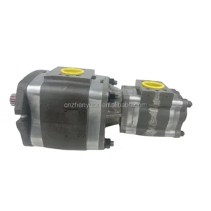
Six. Similar models
1. Different specifications and models of the same series
IPVP5-32-101: Displacement 32 m³/h (533 L/min), suitable for small injection molding machines and hydraulic systems. It is lighter in weight (about 38 kg), making it ideal for applications with high requirements for space and weight
IPVP5-50-101: Displacement 50 m³/h (833 L/min), suitable for medium-sized hydraulic presses and large injection molding machines. It has a greater output power and is suitable for heavy-duty working conditions that require large flow rates
IPVP5-64-101: Displacement 64 m³/h (1067 L/min), with a larger flow rate, suitable for large-scale hydraulic systems and more demanding industrial applications
2. Different series models of the same type
The IPVS series: Similar to the IPVP series, but the IPVS series adopts a different variable control method (usually pressure compensation control), making it more suitable for application scenarios that require constant pressure output
IPH Series: High-pressure series, with a maximum working pressure of up to 250 bar, suitable for industrial applications that require higher pressure, such as high-pressure hydraulic systems and metal forming
Similar products of other brands:
Sumitomo QT series: Similar performance, some models can be directly replaced, and in certain applications, the price is more advantageous
Dipuma IGP series: With different sealing and bearing designs, it has slightly higher efficiency under high-speed and light-load conditions
3. Domestic similar products
CBG series: Internal gear pumps produced by well-known domestic brands, with a displacement range of 16-100 m³/h and a rated pressure of 63-250 bar. They have a significant price advantage and are widely used in the domestic market
YBC series: Domestic high-performance internal gear pumps, using new materials and manufacturing processes, have been improved in terms of anti-pollution and durability. Some models can directly replace imported products
Vii. Precautions for Use
1. Installation points
Fixed foundation
The installation plane should be flat (flatness < 0.1mm) to prevent the pump body from deforming and affecting the gear meshing and sealing performance
The fixing bolts should be tightened evenly (to the specified torque) to prevent uneven force on the shell and leakage
Pipeline connection
The diameter of the oil inlet pipe should be no less than 50mm and the length less than 2m to reduce oil suction resistance and prevent cavitation
The diameter of the oil outlet pipe should be ≥40mm, and ensure that the pressure loss is within the allowable range (<5 bar).
The oil suction pipe must be well sealed to prevent air from entering the system and forming bubbles, which may affect the performance and service life of the pump
Shaft connection
Elastic couplings (such as membrane couplings) must be used, and rigid connections are strictly prohibited
Coaxiality error is less than 0.05mm, angular deviation is less than 0.5°, reducing vibration and bearing load
Regularly inspect the wear of the coupling and replace it in time to prevent the connection from loosening and damaging the pump shaft
2. Startup and Operation management
Startup program
Check the oil level in the fuel tank (at least 200mm above the suction port) and the oil temperature (not lower than 10℃).
Manually turn the wheel 2 to 3 times to ensure there is no jamming
Loosen the exhaust plug, start the pump to fill the pump cavity with oil until continuous oil is discharged, then tighten it
Start the system without load (set the system relief valve to the minimum pressure) and run it for 3 to 5 minutes
Gradually increase the pressure (each time ≤30% of the rated pressure, with an interval of ≥2 minutes). It is strictly prohibited to directly load the cold machine to full load
Operation monitoring
Oil temperature: Normal operating temperature is 20-60℃. If the temperature exceeds 70℃, the machine should be shut down to check the cooling system or the viscosity of the oil
Pressure: Not exceeding the rated value (101 bar), peak not exceeding 120 bar and cumulative time < 10 minutes per hour
Noise: Smooth operation <66 dB. Abnormal noise (>70 dB) indicates possible wear or cavitation, and the machine should be stopped immediately for inspection
Leakage: Slight seepage (<3 drops per minute) is allowed. If the leakage increases, timely maintenance is required to prevent oil contamination and a drop in system pressure
3. Maintenance and care
Daily inspection
Check the oil level, temperature, noise and leakage conditions every shift, and record the operating parameters
Check if the connecting bolts are loose and tighten them in time
Clean the surface of the pump body to prevent the accumulation of oil stains from affecting heat dissipation and observation
Regular maintenance
Every 250 hours: Check the pressure difference of the filter (<0.15MPa), and replace the filter element if necessary
Every 500 hours: Check the contamination level of the oil (≤ISO 4406 19/16 grade), and take samples for testing if necessary
Every 1000 hours: Change the hydraulic oil and clean the oil tank and filter at the same time
Every 2000 hours: Conduct a comprehensive disassembly inspection, measure the gear meshing clearance, and replace worn parts (such as seals and bearings)
Oil Product management
Hydraulic oils of different brands must not be mixed to prevent the reaction of additives and the formation of sediment
In cold regions (ambient temperature < 0℃), low-viscosity hydraulic oil (such as L-HV series) should be used.
Regularly test the viscosity and acid value of the oil to ensure they meet the usage requirements and extend its service life
4. Special Precautions
Prevent dry running
It is strictly prohibited to start the pump without oil. Even a short period of dry operation can cause severe wear and even jamming of the gears and the pump body
After a long period of inactivity, when restarting the pump, clean hydraulic oil should be filled into it to ensure that all friction pairs are fully lubricated
Prevent cavitation
Ensure that the oil suction pipeline is well sealed to prevent air from entering the system
The oil suction height should be less than 500mm, and it is recommended to be less than 300mm to reduce the oil suction resistance
When the oil temperature is too low (<10℃), run it no-load for 15 minutes first to increase the oil temperature before loading to reduce the risk of cavitation
Variable control maintenance
Regularly check whether the variable control mechanism is flexible to prevent jamming and affecting flow regulation
For electro-hydraulic control models, the electrical connections and sensor accuracy should be regularly inspected to ensure control accuracy
The adjustment of variable control parameters should be carried out by professionals to avoid system failures caused by misoperation
Shutdown protection
Before shutting down, the load should be unloaded to low pressure (<20 bar) and run for 3 to 5 minutes. Only when the oil temperature drops below 60℃ should the power be cut off
When the pump is not in use for a long time, the oil in it should be drained or filled with anti-rust oil to prevent internal rusting


