

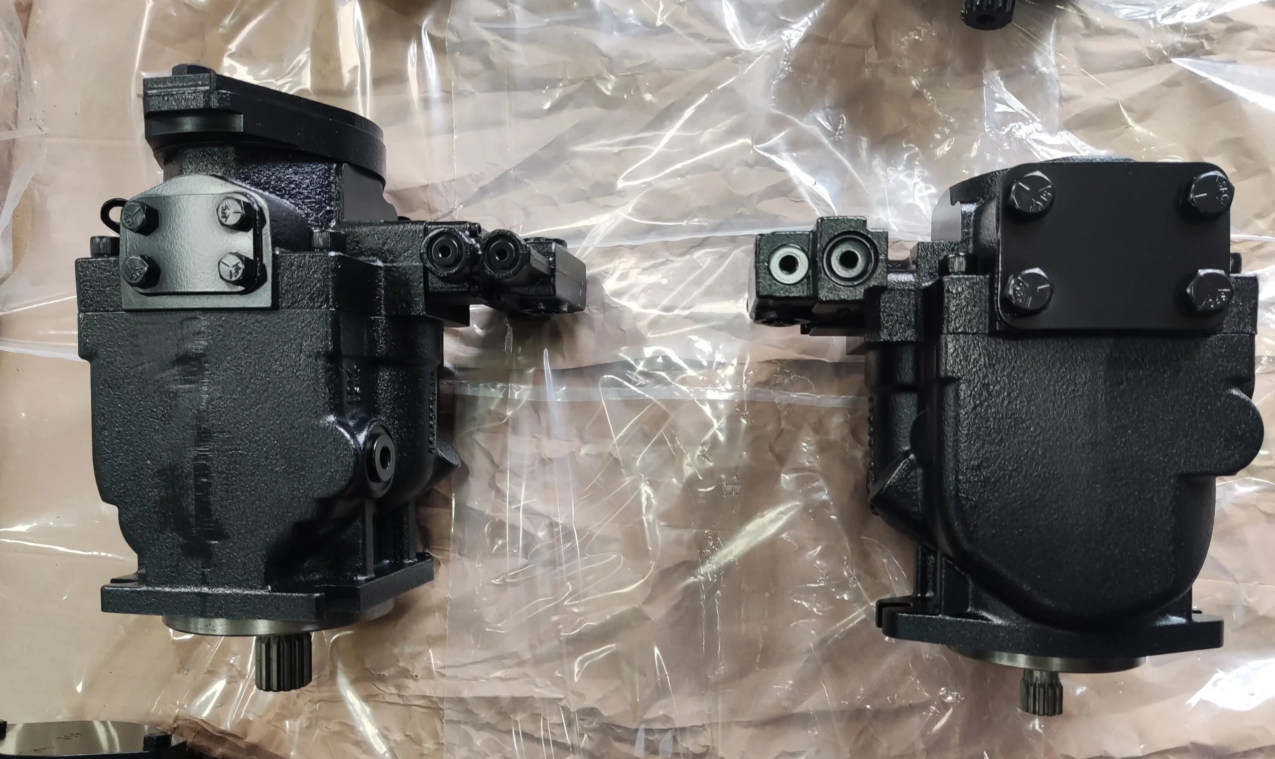
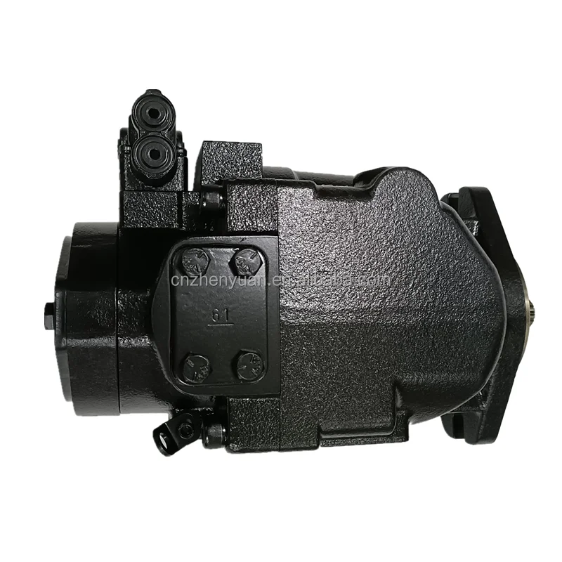
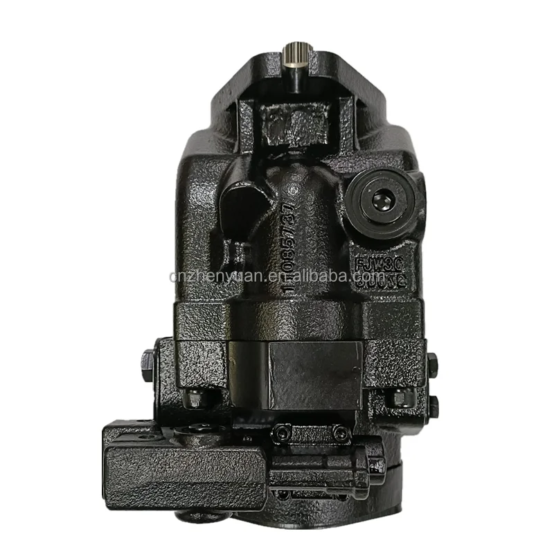
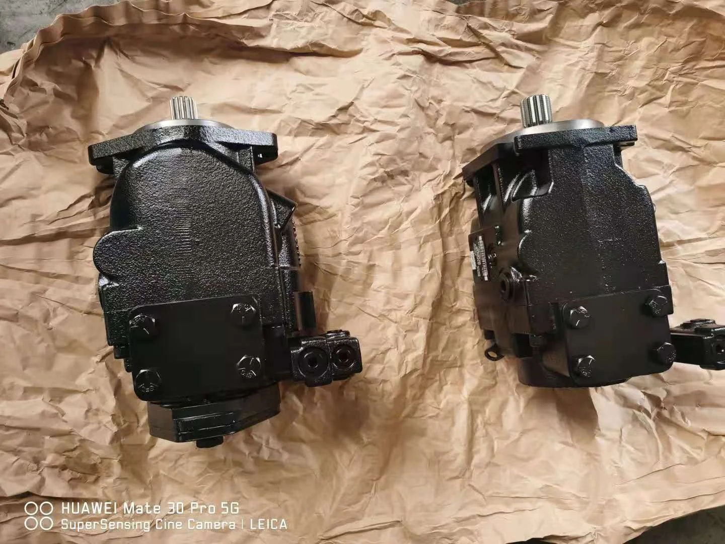
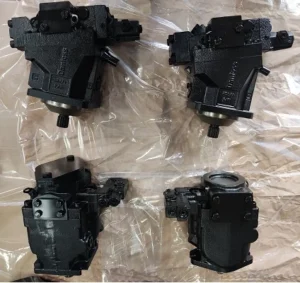
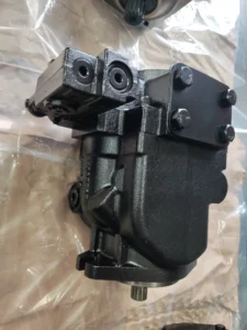
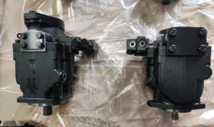

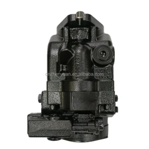

JRR JRL FRR JRRS JRLS FRL JRR060 Piston Pump JRR060BBS3020NNN3C2N2A8NNNNNNNNN Hydraulic Axial Piston Variable Displacement Pump
Basic specifications
Type: The JRRS series of high-pressure open variable piston pumps, 60 indicates a displacement class of approximately 60cc/rev, BBS represents a specific control mode combination, 3020 indicates a maximum working pressure of 30MPa (300bar), NNN3 indicates the shaft end form and seal configuration, and S1 indicates the rotation direction (right rotation). BEA2 represents the variable control mode, and JJJ represents other functional options
Nominal displacement: approximately 60cc/rev (60 milliliters per revolution), theoretical flow rate is directly proportional to the rotational speed
Maximum working pressure: 30MPa (300bar), short-term peak up to 35MPa (350bar)
Rated speed: 1800r/min (revolutions per minute), recommended operating speed range: 1200-2000r/min
Rotation direction: Right rotation (clockwise rotation when viewed from the shaft end), and a left-hand rotation model is also available (S2 code)
Medium temperature: -20℃ to +80℃, recommended working temperature: 20-60℃. Avoid high temperature causing a decrease in oil viscosity
Weight: Approximately 65kg (excluding accessories), compact structure, easy to install
Working parameters
Volumetric efficiency: ≥95%(under rated conditions), efficient energy conversion, and reduced leakage loss
Overall efficiency: ≥88%, with high comprehensive energy utilization efficiency
Applicable media: hydraulic oil, lubricating oil, flame retardant liquid, etc. Viscosity range: 10-300mm²/s, optimal working viscosity: 20-60mm²/s
Noise level: <70dB (A)(standard test conditions), smooth operation, and good noise control
Oil cleanliness: ISO 4406 18/15 grade. A 10μm filter must be installed at the oil inlet to protect the precision componentsIi. Working Principle
Working mechanism of axial variable piston pump
Core structure
It is composed of a drive shaft, cylinder block, plungers (usually 7 to 9), swash plates, distribution plates and variable mechanism
The plungers are evenly distributed along the circumference of the cylinder block, and the plunger heads are in contact with the swash plates through sliding shoes
The oil distribution plate is fixed and has oil suction and discharge Windows on it, which are connected to the inlet and outlet of the pump
Oil absorption process
When the drive shaft rotates the cylinder block, the plunger moves back and forth under the action of the swash plate
When the plunger extends outward (away from the oil distribution plate), the volume of the bottom chamber of the plunger increases, creating a local vacuum
The oil in the fuel tank enters the plunger chamber through the oil suction window of the oil distribution plate under the action of atmospheric pressure
Oil discharge process
The cylinder block continues to rotate, and the plunger begins to retract into the cylinder block under the action of the swash plate
When the volume of the plunger chamber decreases and the oil pressure rises, the check valve that pushes open the oil outlet window of the oil distribution plate
High-pressure oil is discharged to the system through the oil outlet to drive the actuating elements (such as hydraulic cylinders and hydraulic motors).
Principle of variable control
The output flow rate is controlled by adjusting the Angle of the swash plate (β Angle) to change the plunger stroke
The larger the swash plate Angle, the longer the plunger stroke, and the greater the output flow. When the Angle is 0, the flow rate is 0 (the variable is reset to zero)
The BEA2 control mode indicates that the pump adopts electro-hydraulic proportional control, precisely regulating the output flow and pressure through 4-20mA or ±10V signals, with a response time of less than 200ms
Iii. Product Features and Advantages
1. Outstanding variable control performance
Precise flow control: The electro-hydraulic proportional control mode (BEA2) enables a flow regulation resolution of 0.5%, meeting the requirements of precision hydraulic systems
Fast response: The variable control response time is less than 200ms, which can quickly track changes in system load and reduce pressure fluctuations
Energy optimization: Output flow as needed, avoiding the overflow loss of traditional quantitative pumps, and the energy-saving effect can reach 30-50%
Bidirectional flow: By changing the inclination direction of the swash plate, bidirectional fluid transportation can be achieved, simplifying the system design
2. Excellent high-pressure working ability
High working pressure: Rated pressure 30MPa, short-term peak up to 35MPa, suitable for various high-pressure hydraulic systems
Stable output: It maintains a high volumetric efficiency (≥95%) even under high-pressure conditions, ensuring the stable operation of the system
Impact resistance: It can withstand short-term overloading (120% of the rated pressure), protecting the system from sudden impact damage
3. Structural and reliability advantages
Durable and sturdy: Equipped with a high-strength cast iron housing and hardened plungers, the average mean time between failures exceeds 10,000 hours
Low-noise operation: Optimized fluid mechanics design and precise manufacturing keep noise below 70dB, improving the working environment
Strong self-priming ability: It can be started without additional pump priming, and the suction lift can reach 4 meters (depending on the viscosity of the medium)
Easy maintenance: Modular design makes it easy to disassemble and replace worn parts, resulting in low maintenance costs
4. Wide adaptability to various media
Wide viscosity adaptability range: It can convey various hydraulic media with viscosities ranging from 10 to 300mm²/s, adapting to different application scenarios
High contamination tolerance: Compared with other pump types, it is less sensitive to oil contamination, thus extending the filter replacement cycle
Wide temperature adaptability: It can operate in an ambient temperature range of -20 ℃ to +80℃, adapting to extreme working conditions
Iv. Usage Functions and Purposes
Core functions
Convert mechanical energy into hydraulic energy to provide high-pressure and controllable fluid power for the hydraulic system
Precisely control fluid flow and pressure to achieve precise positioning and force control of actuating elements (hydraulic cylinders, motors)
In coordination with the electrical control system, it realizes the automated production process, enhancing efficiency and product quality
Main application fields
Construction machinery
Excavators, loaders and bulldozers: Provide high-pressure power for working devices (boom, bucket arm, bucket) to achieve precise operation
Rollers and pavers: Provide stable hydraulic sources for vibration systems and walking drives to ensure construction quality
Industrial hydraulic system
Injection molding machine: It provides high-pressure clamping force and precise injection control to ensure the accuracy of plastic products
Hydraulic press: Provides stable high pressure for metal forming and pressing processes, with a maximum pressure of up to 300bar
Machine tool: It provides power for the movement of the worktable and the feed system, ensuring processing accuracy and surface quality
Metallurgical and Mining equipment
Steel plant rolling mills: Provide high-pressure hydraulic power for roller drive and reduction systems to ensure the accuracy of sheet rolling
Mining machinery: Provides reliable hydraulic sources for lifting, towing and crushing equipment, adapting to harsh working conditions
Energy equipment
Wind turbine generator set: It provides hydraulic power and braking control for yaw and pitch systems, ensuring power generation efficiency and equipment safety
Hydraulic machinery: Provides stable hydraulic power for gate control and ship lock lifting
Special equipment
Ship deck machinery (cranes, winches) : Provide reliable hydraulic power and adapt to harsh Marine environments
Aviation ground equipment: Provides portable hydraulic sources for aircraft towing and landing gear maintenance
V. Applicable Machines and Scenarios
1. Typical applicable machines
Injection molding equipment
The JRRS60BBS3020 is particularly suitable for medium and small-sized injection molding machines (with a clamping force of 1000-2000 tons), providing stable high-pressure (300bar) clamping force and precise injection control
Electro-hydraulic proportional control (BEA2) significantly reduces the flow output of injection molding machines during the pressure-holding stage, cutting energy consumption by 50-80% while maintaining a stable pressure
The rapid response feature ensures uniform mold closure and prevents defects such as flash and deformation in plastic products
Hydraulic presses and metal forming equipment
It is applicable to all kinds of hydraulic presses (presses, bending machines, punch presses), with a maximum working pressure of 30MPa, meeting the requirements of most metal forming processes
The flow rate is automatically adjusted at different working stages (fast forward, working forward, pressure holding, and return) to improve work efficiency
Integrated with the numerical control system, it realizes closed-loop control of position, pressure and flow, ensuring high-precision forming of complex parts
Working device of construction machinery
The hydraulic system of the excavator’s boom, bucket arm and bucket: provides a high-pressure oil source of 300bar to ensure the digging force and operational accuracy
The lifting and tilting system of the loader: ensuring smooth movement and precise control under heavy load conditions
Pilot control system for construction machinery: Provides a stable low-pressure oil source (10-30bar) to achieve easy operation
2. Characteristics of applicable scenarios
Multi-axis systems requiring precise synchronous control:
For instance, in ship steering gears and multi-cylinder synchronous lifting systems, the precise variable control of JRRS60BBS3020 can achieve a synchronization accuracy of less than 0.5%
Working conditions with large and frequent load changes:
For instance, in forging equipment and stamping machinery, the pump can automatically adjust the output according to the load, avoiding overflow loss and achieving significant energy savings
A hydraulic servo system requiring rapid response:
For instance, in precision machining machines and aviation simulation platforms, electro-hydraulic proportional control (BEA2) ensures a response time of less than 200ms, guaranteeing the dynamic performance of the system
Large-scale hydraulic systems that are energy-efficient and highly effective are needed
Variable control enables the pump to output a small flow rate at low loads, significantly reducing energy consumption. It is particularly suitable for intermittent operation equipment
Six. Similar models
1. Different specifications and models of the same series
JRRS45BBS3020: With a displacement of approximately 45cc/rev and a lighter weight (about 55kg), it is suitable for small hydraulic systems and scenarios with high space requirements
JRRS75BBS3020: With a displacement of approximately 75cc/rev, it offers a larger output flow rate, making it suitable for large-scale hydraulic systems and heavy-duty conditions that require high flow rates
JRRS60BPC28NN: Compared with BBS3020, it has a maximum working pressure of 28MPa and a different control mode (P represents pressure compensation control), making it suitable for applications that require constant pressure output
2. Different series models of the same type
JRLS60 series: Compared with the JRRS60 series, it adopts a different variable control mechanism. The “L” indicates a swing cylinder structure, which is suitable for certain special installation requirements scenarios
FRR090 series: With a larger displacement (approximately 90cc/rev), it is suitable for ultra-large hydraulic systems, such as mining machinery and large presses
ERR series (such as ERR100, ERR130) : With different pump body structures and variable control methods, they are suitable for special industrial application scenarios
3. Domestic similar products
A10VSO Series (domestic Rexroth imitation) : Displacement range 28-140cc/rev, working pressure up to 35MPa. Some models can directly replace the JRRS series, with obvious price advantages
YCY series: Domestic high-performance variable piston pumps, using new materials and manufacturing processes, have been improved in terms of anti-pollution and durability. Some models can rival the JRRS series
Vii. Precautions for Use
1. Installation points
Fixed foundation
The installation plane should be flat (flatness < 0.1mm) to prevent the pump body from deforming and affecting the movement of the plunger and the sealing performance
The fixing bolts should be tightened evenly (to the specified torque) to prevent uneven force on the shell and leakage
Pipeline connection
The diameter of the oil inlet pipe should be no less than 40mm and the length less than 2m to reduce oil suction resistance and prevent cavitation
The outlet pipe diameter should be no less than 32mm to ensure that the pressure loss is within the allowable range (<5bar).
The oil suction pipe must be well sealed to prevent air from entering the system and forming bubbles, which may affect the performance and service life of the pump
Shaft connection
Elastic couplings (such as membrane couplings) must be used, and rigid connections are strictly prohibited
Coaxiality error is less than 0.05mm, angular deviation is less than 0.5°, reducing vibration and bearing load
Regularly inspect the wear of the coupling and replace it in time to prevent the connection from loosening and damaging the pump shaft
2. Startup and Operation management
Startup program
Check the oil level in the fuel tank (at least 200mm above the suction port) and the oil temperature (not lower than 10℃).
Manually turn the wheel 2 to 3 times to ensure there is no jamming
Loosen the exhaust plug, start the pump to fill the pump cavity with oil until continuous oil is discharged, then tighten it
Start the system without load (set the system relief valve to the minimum pressure) and run it for 3 to 5 minutes
Gradually increase the pressure (each time ≤30% of the rated pressure, with an interval of ≥2 minutes). It is strictly prohibited to directly load the cold machine to full load
Operation monitoring
Oil temperature: Normal operating temperature is 20-60℃. If the temperature exceeds 70℃, the machine should be shut down to check the cooling system or the viscosity of the oil
Pressure: Not exceeding the rated value (30MPa), peak not exceeding 35MPa and cumulative time less than 10 minutes per hour
Noise: Smooth operation <70dB. Abnormal noise (>75dB) indicates possible wear or cavitation, and the machine should be stopped immediately for inspection
Leakage: Slight seepage (<5 drops per minute) is allowed. If the leakage increases, timely maintenance is required to prevent oil contamination and a drop in system pressure
3. Maintenance and care
Daily inspection
Check the oil level, temperature, noise and leakage conditions every shift, and record the operating parameters
Check if the connecting bolts are loose and tighten them in time
Clean the surface of the pump body to prevent the accumulation of oil stains from affecting heat dissipation and observation
Regular maintenance
Every 250 hours: Check the pressure difference of the filter (<0.15MPa), and replace the filter element if necessary
Every 500 hours: Check the contamination level of the oil (≤ISO 4406 18/15 grade), and take samples for testing if necessary
Every 1000 hours: Change the hydraulic oil and clean the oil tank and filter at the same time
Every 2000 hours: Conduct a comprehensive disassembly inspection, measure the fit clearance between the plunger and the cylinder block, and replace worn parts (such as plungers, sliding shoes, and bearings)
Oil Product management
Hydraulic oils of different brands must not be mixed to prevent the reaction of additives and the formation of sediment
In cold regions (ambient temperature < 0℃), low-viscosity hydraulic oil (such as L-HV series) should be used.
Regularly test the viscosity and acid value of the oil to ensure they meet the usage requirements and extend its service life
4. Special Precautions
Prevent dry running
It is strictly prohibited to start the pump without oil. Even a short period of dry operation can cause severe wear or even jamming of the plunger and cylinder block
After a long period of inactivity, when restarting the pump, clean hydraulic oil should be filled into it to ensure that all friction pairs are fully lubricated
Prevent cavitation
Ensure that the oil suction pipeline is well sealed to prevent air from entering the system
The oil suction height should be less than 500mm, and it is recommended to be less than 300mm to reduce the oil suction resistance
When the oil temperature is too low (<10℃), run it no-load for 15 minutes first to increase the oil temperature before loading to reduce the risk of cavitation
Variable control maintenance
Regularly check whether the variable control mechanism is flexible to prevent jamming and affecting flow regulation
For electro-hydraulic control models (such as BEA2), the electrical connections and sensor accuracy should be regularly inspected to ensure control accuracy
The adjustment of variable control parameters should be carried out by professionals to avoid system failures caused by misoperation
Shutdown protection
Before shutting down, the load should be unloaded to low pressure (<20bar) and run for 3 to 5 minutes. Only when the oil temperature drops below 60℃ should the power be cut off
When the pump is not in use for a long time, the oil in it should be drained or filled with anti-rust oil to prevent internal rusting


