


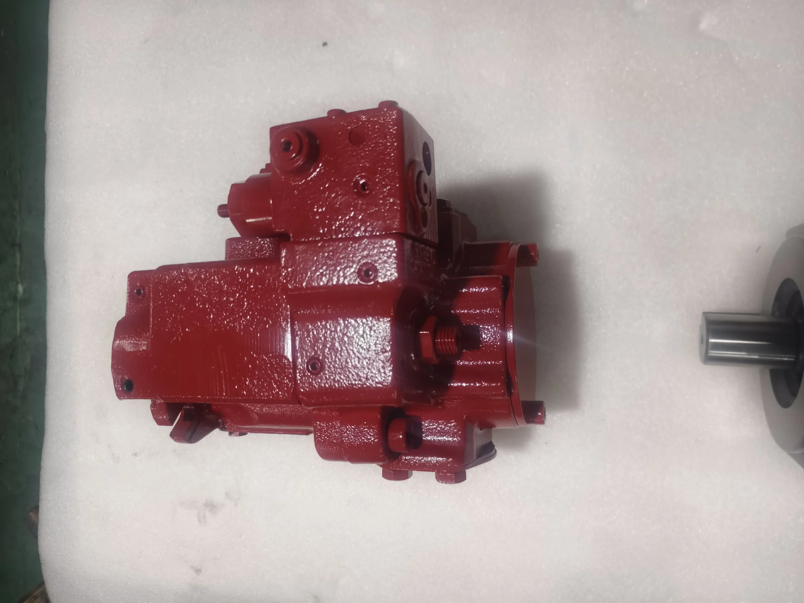
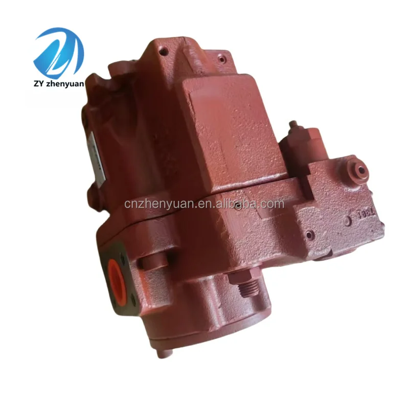
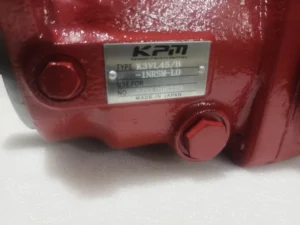


K3VL Piston Hydraulic Pump K3VL28/45/80/140/200 Series K3VL45/B-1NRSM-P0-01 Axial Piston Variable Displacement Pump
Displacement: 45 cm³/rev, with an output flow rate of approximately 67.5 L/min at 1500 rpm. The displacement can be continuously adjusted through a variable mechanism.
– Pressure range: Rated working pressure 32 MPa (326 kgf/cm²), peak pressure up to 35 MPa (357 kgf/cm²), continuous peak working cycle not exceeding 20%. The rated pressure of the oil suction port is ≥0 MPa (under steady-state conditions), and the oil discharge pressure of the shell is ≤0.3 MPa.
– Speed range: The maximum speed in self-priming condition is 2400 rpm (subject to oil suction conditions), and the maximum speed can reach 3000 rpm under boost pressure. The minimum stable rotational speed is no less than 100 rpm, adapting to the output requirements of different power sources.
– Power parameters: Under the rated pressure of 32 MPa and 1500 rpm, the input power is approximately 36.3 kW, the volumetric efficiency is ≥94%, and the total efficiency is ≥90%.
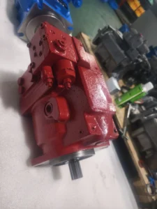
– Structural parameters: Weight approximately 25 kg. It adopts a lateral oil inlet and outlet design. The shaft end supports flat key or involute spline connection, and is compatible with SAE/ISO/JIS standard installation dimensions.
– Control mode: It adopts load sensitivity (LS) + constant pressure compound control (corresponding to NRSM code), supports remote pressure adjustment and flow self-adaptation, and can achieve compound functions such as unloading and horsepower control.Ii. Working Principle
This pump is a swashplate axial variable plunger pump. The core mechanically adjusts the inclination Angle of the swashplate to change the plunger stroke, thereby achieving continuous variable flow. Combined with a load-sensitive control system, it realizes energy-saving operation. The specific process is divided into three stages:
1. Oil suction stage: The power source drives the transmission shaft to rotate the cylinder body. Under the guiding action of the return spring and the swash plate, the plunger extends outward, and the volume of the plunger chamber instantly increases to form a negative pressure. The hydraulic oil is sucked into the plunger chamber through the oil suction valve group.
2. Oil pressure stage: As the cylinder block continues to rotate, the plunger reaches the high-pressure area of the swash plate and is forcibly pressed into the cylinder block by the swash plate. The volume of the plunger chamber sharply shrinks, and the oil is compressed to a high-pressure state and then output to the system through the oil pressure window of the distribution plate.
3. Variable control stage: The load-sensitive controller detects the system load pressure and flow demand in real time, and changes the swash plate inclination Angle by controlling the oil to push the variable piston – when the load increases, the inclination Angle increases and the output flow increases. When the load decreases, the inclination Angle decreases and the flow rate drops accordingly. When the system pressure reaches the set value, it automatically adjusts to a state of low pressure with high flow or high pressure with low flow, achieving dynamic matching of pressure and flow.
Iii. Product Features and Advantages
– Low noise and low pulsation: With an optimized distribution plate structure and A unique pressure buffering mechanism, the amplitude of pressure pulsation is significantly reduced. The operating noise is 3-5 dB(A) lower than that of traditional models, making it suitable for industrial scenarios that are sensitive to noise.
– High efficiency and long service life: Utilizing high-load capacity bearings and high-strength piston-slide shoe assemblies, combined with an optimized valve plate oil film design, the self-priming capacity is enhanced (steady-state oil suction pressure can reach 0 MPa), maintaining a volumetric efficiency of over 94% for a long time, and the design life can exceed 10,000 hours.
– Rich control methods: It integrates multiple control modes such as load sensitivity (LS), constant pressure (PC), and horsepower control (HP), which can be combined according to system requirements. It supports remote control and electromagnetic proportional regulation, and is suitable for complex hydraulic circuits.
– Strong integration and adaptability: Supports direct installation of auxiliary gear pumps in accordance with SAE/ISO/JIS standards and series connection of multiple pumps, which can form a composite pump set to save installation space. The shaft end and installation flange are compatible with multiple specifications and can be adapted to different mainframe equipment without major modifications.
– Resistant to harsh working conditions: It adopts a high-strength cast iron shell and an anti-pollution sealing structure, which can adapt to the dust and vibration environment of construction machinery and the humid and corrosive environment of ships. The working oil temperature adaptability range is 15-65℃, demonstrating strong environmental adaptability.
Iv. Usage Functions and Purposes
Core function: It provides a high-pressure and controllable hydraulic power source for the hydraulic system, driving hydraulic cylinders, hydraulic motors and other actuating components to complete linear reciprocating or rotary motion. Through load sensitive control, it achieves precise matching of power output and load demand, reducing system energy consumption.
– Main uses:
In the field of construction machinery: It provides power for the bucket movement of excavators, the lifting mechanism of loaders, and the vibration system of rollers.
– Industrial manufacturing field: Drives high-pressure actions such as mold closing in injection molding machines, injection in die-casting machines, and pressing in hydraulic presses, suitable for plastic machinery and metal processing equipment;
– Special machinery field: Impact mechanisms for rock drills in mines, deck cranes on ships, material distribution systems for asphalt pavers, and propulsion devices for shield machines;
In the field of agricultural machinery: heavy-duty actuators such as suspension systems suitable for large tractors and cutting drives for combine harvesters.
V. Applicable Machines and Scenarios
1. Excavator/rotary drilling rig: Suitable for multi-action compound working conditions such as excavation and rotation. Load sensitive control can reduce pressure shock during action switching, and a peak pressure of 35 MPa meets the requirements of crushing operations.
2. Injection molding machine/ceramic press: The constant pressure control mode can precisely maintain the closing pressure and pressing pressure. The flow rate can be adaptively adjusted to suit the production rhythm of products of different specifications. The low pulsation feature enhances the molding accuracy of the products.
3. Crawler crane: The multi-pump series design can simultaneously drive multiple mechanisms such as lifting, luffing and slewing. The high-strength shell and bearings can withstand the impact load during hoisting operations and are suitable for complex outdoor environments.
4. Rock drills/roadheaders for mining: The high self-priming capacity and anti-pollution structure are suitable for the underground dust environment. The continuous high-pressure output meets the power requirements of rock drilling impact and propulsion actions. The long service life design reduces the frequency of underground maintenance.
5. Deck machinery for ships: The structure design that is resistant to moisture and corrosion is suitable for Marine environments and can drive equipment such as anchor winches and hoists. Load sensitive control enhances fuel economy during ship operations.
Six. Similar models
– Same series models: The core structure is the same, but the displacement and control methods are different, adapting to various flow demand scenarios, including K3VL28 (28 cm³/rev), K3VL60 (60 cm³/rev), K3VL80 (80 cm³/rev), K3VL200 (200 cm³/rev), etc. Among them, the control mode of K3VL28/B-1NRSM-P0 is exactly the same as that of this model, with only the displacement reduced.
– Competing alternative models:
A4VSO40 series: Rated pressure 32 MPa, load-sensitive control, strong shock resistance, but the noise is 2-3 dB higher than that of this model. It is suitable for heavy-load scenarios in construction machinery.
-A10VSO45 series: Medium and high pressure positioning, similar displacement, more compact volume, but with a peak pressure of only 31 MPa, suitable for industrial light-load working conditions.
– Domestic KD-A4V45 series: It features load sensitivity and electrical proportional control, supports CAN bus communication, and has a cost 15%-20% lower than this model. It is suitable for domestic host equipment that is sensitive to cost.
Vii. Precautions for Use
1. Installation requirements:
The coaxiality error between the drive shaft and the prime mover (motor/engine) should be ≤ 0.1mm. It is recommended to use an elastic coupling for connection to avoid bearing damage caused by rigid impact.
2. The diameter of the oil suction pipeline should be ≥φ 32mm, the length should not exceed 1.5m, and the number of elbows should not exceed 2. The oil suction port should be more than 50mm lower than the liquid level in the oil tank to prevent cavitation.
3. The oil drain pipe must be returned to the oil tank separately. The pipe opening should be higher than the liquid level in the oil tank and not submerged. The back pressure should be ≤0.3 MPa. It is strictly prohibited to be connected in parallel with the return oil pipeline.
4. Oil Management
It is recommended to use ISO VG 46 or 68 anti-wear hydraulic oil. The working oil temperature should be controlled between 15 and 65℃. When the oil temperature in the oil tank exceeds 65℃, the cooling system needs to be activated.
5. The oil cleanliness must reach NAS grade 8 (ISO 16/13). When refueling, it must pass through an oil filter vehicle with a filtration accuracy of ≤25 μm. The oil and filter element need to be replaced after the first 200 hours of operation, and then every 2000 hours thereafter.
6. Operation and Maintenance
Before starting, clean hydraulic oil should be filled into the pump through the oil drain port of the shell. Press it 3 to 5 times to confirm the correct rotation direction, then run it under low pressure without load for 5 to 10 minutes, and gradually load it to the rated pressure.
7. During operation, it is necessary to monitor the shell temperature (not exceeding 85℃), pressure fluctuations (≤± 0.5MPa), and noise changes. If any abnormality occurs, stop the machine immediately for inspection, with a focus on checking the wear of the distribution plate and the leakage of the sealing parts.
8. Before restarting after long-term storage, it is necessary to disassemble and check the lubrication status of the plunger – slipper assembly, replace the aged sealing parts, and avoid dry friction damage.
9. Safe Operation
It is strictly prohibited to operate for a long time at pressures exceeding the peak pressure (35 MPa) or the maximum speed (3000 rpm). The single peak operation time shall not exceed 30 seconds.
10. Before maintenance, the power source must be cut off. The system pressure should be released through the pressure relief valve. Disassembly can only be carried out when the oil temperature drops below 40℃.
11. Operators must wear goggles and oil-resistant gloves to prevent injury caused by high-pressure oil spraying.


