


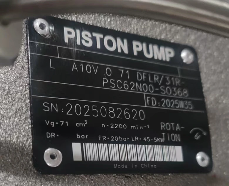
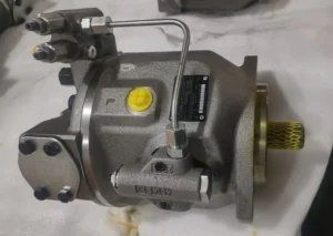

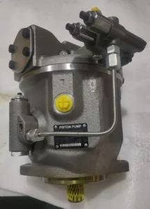
Basic specifications
Type: Swashplate axial variable piston pump. 71 indicates a nominal displacement of approximately 71cc/rev, DFLR represents the control mode, 31R indicates the rotation direction and installation form, and PSC62N00 is the oil port and special function code
Nominal displacement: 71cc/rev (71 milliliters per revolution), theoretical flow rate is approximately 106.5L/min at 1500r/min
Rated pressure: 28MPa (280bar), short-term peak pressure up to 35MPa (350bar), suitable for high-pressure hydraulic systems
Rated speed: 1900-2200r/min, maximum allowable speed 2500r/min, minimum stable speed ≥300r/min
Rotation direction: R indicates right rotation (clockwise when viewed from the shaft end), and some models can be optionally left rotation
Weight: approximately 33kg (excluding accessories), compact structure, and high power density
Working parameters
Volumetric efficiency: ≥95% (under rated conditions), with low energy conversion loss
Overall efficiency: ≥88%, with highly efficient comprehensive performance
Applicable medium: Hydraulic oil (viscosity index ≥90), flame retardant liquid, etc. Viscosity range: 10-300mm²/s, optimal working viscosity: 20-60mm²/s
Medium temperature: -20℃ to +80℃, recommended working temperature: 30-60℃. Avoid high temperature causing a decrease in oil viscosity
Noise level: <70dB (A), smooth operation, and good noise control
Oil cleanliness: ISO 4406 18/15 grade. A 10μm precision oil inlet filter must be installed to protect the precision componentsIi. Working Principle
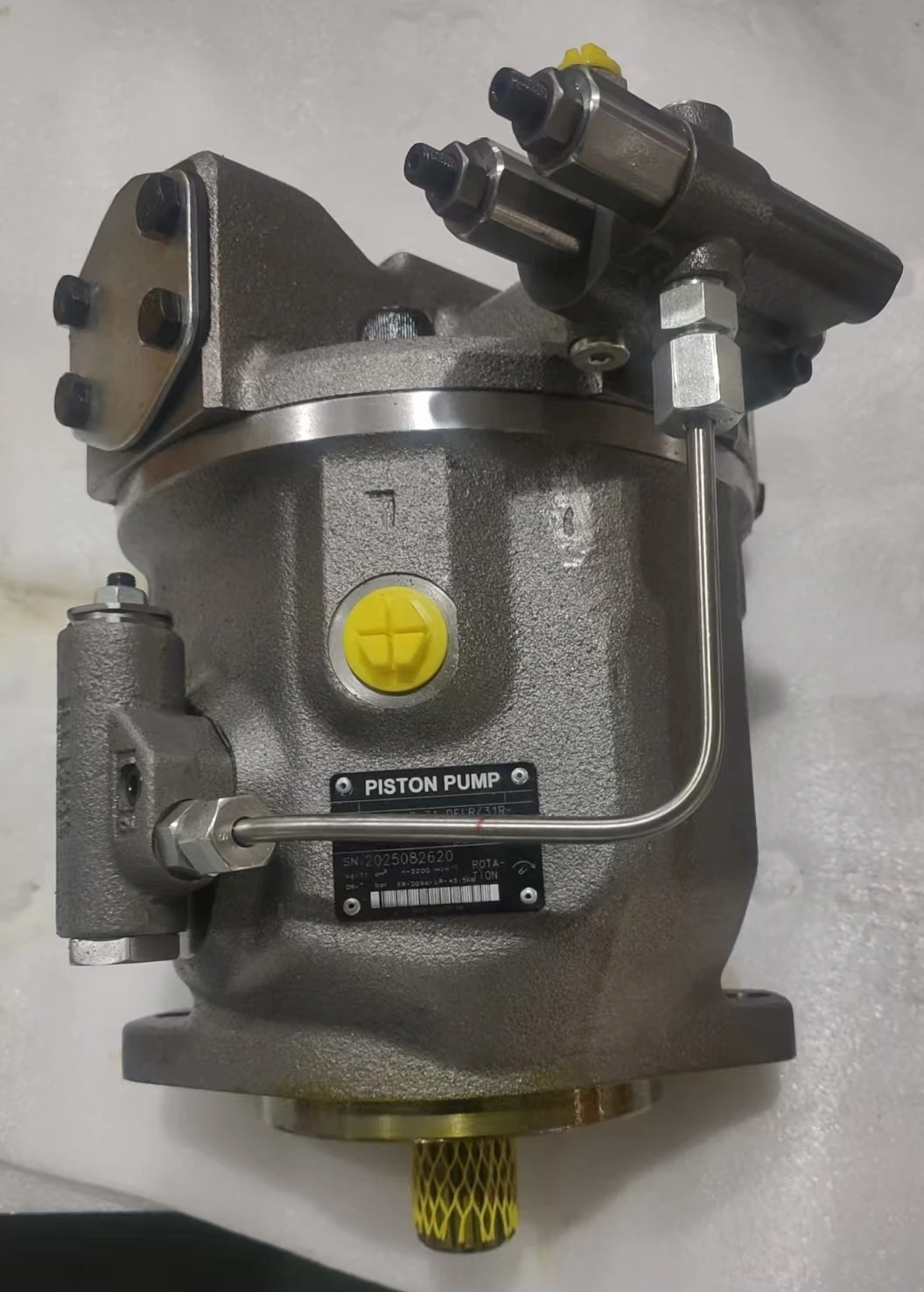
Working mechanism of swash plate axial piston pump
Core structure
It is composed of a drive shaft, cylinder block, plungers (usually 7), swash plates, distribution plates and variable mechanism
The plungers are evenly distributed along the circumference of the cylinder block, and the plunger heads come into contact with the swash plates through sliding shoes
The oil distribution plate is fixed on the pump casing and is equipped with oil suction and discharge Windows, which are respectively connected to the inlet and outlet
Oil absorption process
The transmission shaft drives the cylinder block to rotate, and the swash plate forms an inclination Angle with the cylinder block axis
When the plunger rotates to the high point of the swash plate, it is forced to extend outward, increasing the volume of the plunger cavity and creating a vacuum
The oil in the fuel tank enters the plunger chamber through the oil suction window of the oil distribution plate under the action of atmospheric pressure
Oil discharge process
The cylinder block continues to rotate. When the plunger reaches the lower part of the swash plate, it is pushed back into the cylinder block, and the volume of the plunger cavity decreases
When the oil pressure rises, the check valve of the oil distribution plate’s oil discharge window is pushed open, and the high-pressure oil is discharged through the outlet
Each plunger completes one oil suction and discharge cycle per revolution. The continuous operation of multiple plungers ensures a stable flow rate
The principle of DFLR variable control
DFLR stands for “Pressure-Flow-Power Compound Control”, which is the core technology of this pump
The output flow rate is controlled by adjusting the plunger stroke by changing the inclination Angle of the swash plate
Pressure control (DR) : When the system pressure reaches the set value, the displacement is automatically reduced to prevent overpressure in the system
Flow control (FR) : Maintain a constant output flow rate, unaffected by changes in system pressure
Power control (FL) : Maintain the output power of the pump constant, that is, the product of pressure and flow rate is a constant, to prevent the prime mover from overloading
The control response time is less than 200ms, which can quickly track load changes and reduce pressure fluctuations
Iii. Product Features and Advantages
1. Outstanding variable control performance
Triple control integration: DFLR control simultaneously achieves precise regulation of pressure, flow rate and power, adapting to complex working conditions
Intelligent load matching: Automatically sense system requirements, output flow as needed, and achieve energy-saving effects of 30-50%
Power protection function: Prevents the prime mover from overloading, extends the equipment’s lifespan, and enhances system safety
Precise flow control: Variable range 0-100%, high control accuracy, suitable for precision hydraulic systems
2. Excellent high-voltage performance and reliability
High working pressure: 28MPa rated pressure, short-term 35MPa, meeting the requirements of various high-pressure applications
Sturdy and durable structure: Made of high-strength materials and with precise manufacturing processes, the average mean time between failures exceeds 10,000 hours
Strong impact resistance: It can withstand a short-term impact of 120% of the rated pressure and adapt to harsh working conditions
Low-noise operation: Optimized fluid mechanics design keeps noise below 70dB, improving the working environment
3. Structural and maintenance advantages
Compact design: Small radial dimensions, light weight, easy to install, suitable for space-constrained scenarios
High self-priming capacity: It can be started without additional priming, and the suction lift can reach 4 meters (depending on the viscosity of the medium)
Easy maintenance: Modular design makes it easy to disassemble and replace worn parts, resulting in low maintenance costs
Through-shaft structure: Auxiliary pumps can be connected in series to enhance system integration and reduce space occupation
4. Wide applicability
Wide range of medium adaptability: It can use various hydraulic media and adapt to different working environments
Strong temperature adaptability: Operating temperature range of -20℃ to +80℃, suitable for extreme working conditions
Multiple installation methods: Various shaft end and connection configurations facilitate system integration
Iv. Usage Functions and Purposes
Core functions
Convert mechanical energy into hydraulic energy to provide high-pressure and controllable fluid power for the hydraulic system
Precisely control fluid flow and pressure to achieve precise motion control of actuating elements (hydraulic cylinders, motors)
In coordination with the electrical control system, it realizes the automated production process, enhancing efficiency and product quality
Main application fields
Construction machinery
Excavator: Provides high-pressure power for the boom, bucket arm and bucket to achieve precise excavation
Loader: Provides a stable hydraulic source for the lifting and tilting systems to ensure smooth operation under heavy load conditions
Rollers and pavers: They provide power for vibration systems and walking drives, ensuring construction quality
Industrial hydraulic system
Injection molding machine: It provides high-pressure clamping force and precise injection control to ensure the accuracy of plastic products
Hydraulic press: Provides stable high pressure for metal forming and pressing processes, with a maximum pressure of up to 280bar
Machine tool: It provides power for the movement of the worktable and the feed system, ensuring processing accuracy
Special Vehicles and equipment
Aerial work platform: It provides power for the lifting and rotating systems to ensure the platform’s stability and precise positioning
Ship deck machinery: Provides hydraulic power for cranes and winches, adapting to harsh Marine environments
Agricultural machinery: Provides reliable power for the hydraulic systems of harvesters and tractors
Other fields
Concrete pump truck: Provides high-pressure power for the pumping system to ensure the efficiency of concrete transportation
Rotary drilling rig: As an auxiliary pump, it provides a stable hydraulic source to enhance drilling efficiency
Mining machinery: Provides reliable hydraulic power for lifting, towing and crushing equipment
V. Applicable Machines and Scenarios
1. Typical applicable machines
6-8 ton class excavators
It is particularly suitable for 6-8 ton excavators such as Sany 60/65, XCMG 75/80, Lovol 75, and Sunward Intelligent 80
As the main pump, it provides strong power to ensure the excavation force and operational accuracy
DFLR control enables excavators to automatically distribute flow during compound actions, reducing energy consumption and improving fuel efficiency
Medium-sized injection molding machine
Provide stable high-pressure clamping force for injection molding machines with a clamping force of 1,000 to 2,000 tons
During the pressure-holding stage, the flow output is significantly reduced, lowering energy consumption by 50-80% while maintaining a stable pressure
Precise control ensures uniform mold closure and prevents defects such as flash and deformation in plastic products
Hydraulic press
It provides a stable high pressure of 280bar for the metal sheet forming and pressing processes
The DFLR control enables the pump to automatically adjust the output at different pressing stages, reducing overflow losses and achieving significant energy savings
The pressure cut-off function protects the system safety and prevents overpressure from damaging the molds and equipment
2. Characteristics of applicable scenarios
Construction machinery operating conditions with large and frequent load variations
For instance, during the compound movements of excavators and the loading and unloading processes of loaders, the pump can automatically adjust the output according to the load, avoiding overflow losses and achieving significant energy savings
Multi-axis systems requiring precise synchronous control:
For instance, in multi-cylinder synchronous lifting and ship steering gear systems, the precise variable control of LA10VO71 can achieve a synchronization accuracy of less than 0.5%
Industrial automation equipment requiring rapid response:
For instance, in robot joint drives and precision machining machines, the variable response time is less than 200ms, ensuring precise and smooth movements
Large-scale hydraulic systems that are energy-efficient and highly effective are needed
Variable control enables the pump to output a small flow rate at low loads, significantly reducing energy consumption. It is particularly suitable for intermittent operation equipment
Construction machinery operating in harsh environments:
Such as in mines and water conservancy projects, the temperature adaptability range of -20℃ to +80℃ and the sturdy and durable structure ensure long-term reliable operation
Six. Similar models
1. Different specifications and models of the same series
LA10VO45: With a displacement of approximately 45cc/rev and a lighter weight (about 28kg), it is suitable for small hydraulic systems and scenarios with high space requirements
LA10VO100: With a displacement of approximately 100cc/rev, it offers a larger output flow rate and is suitable for medium-sized construction machinery and applications requiring high flow rates
LA10VO140: With a displacement of approximately 140cc/rev, it offers greater output flow and torque, making it suitable for large-scale construction machinery and heavy industrial equipment
2. Different series models of the same type
A10VSO71: Another series of the same brand, featuring a different variable control mechanism, is suitable for industrial fixed equipment and has a stronger anti-pollution ability
A11VO75: A large-displacement series of the same brand, with a displacement of 75cc/rev. It offers more stable shaft end support and is suitable for heavy-load continuous operation
A2F71: A series of quantitative motors of the same brand, it can be used as a hydraulic motor and form a pump-motor system with the LA10VO71 pump
3. Domestic similar products
YCY14-1B series: Domestic high-performance variable piston pumps with similar performance but more economical prices, suitable for the domestic construction machinery matching and maintenance market
Other domestic alternatives to the A10VO series: such as similar products produced by brands like Huade and Liyuan, which offer high cost performance and have a complete service network
Vii. Precautions for Use
1. Installation points
Fixed foundation
The installation plane must be flat (flatness < 0.1mm) to prevent the pump body from deforming and affecting the movement of the plunger
Tighten the fixing bolts evenly (to the specified torque) to prevent uneven force on the shell and leakage
Pipeline connection
The diameter of the oil inlet pipe should be no less than 40mm and the length less than 2m to reduce oil suction resistance and prevent cavitation
The outlet pipe diameter should be no less than 32mm to ensure that the pressure loss is within the allowable range (<5bar).
The oil suction pipe must be well sealed to prevent air from entering the system and forming bubbles, which may affect the performance and service life of the pump
Shaft connection
Elastic couplings (such as membrane couplings) must be used, and rigid connections are strictly prohibited
Coaxiality error is less than 0.05mm, angular deviation is less than 0.5°, reducing vibration and bearing load
Regularly inspect the wear of the coupling and replace it in time to prevent the connection from loosening and damaging the pump shaft
2. Startup and Operation management
Startup program
Check the oil level in the fuel tank (at least 200mm above the suction port) and the oil temperature (not lower than -10 ℃).
Manually turn the wheel 2 to 3 times to ensure there is no jamming
Loosen the exhaust plug, start the pump to fill the pump cavity with oil until continuous oil is discharged, then tighten it
Start the system without load (set the system relief valve to the minimum pressure) and run it for 3 to 5 minutes
Gradually increase the pressure (each time ≤30% of the rated pressure, with an interval of ≥2 minutes). It is strictly prohibited to directly load the cold machine to full load
Operation monitoring
Oil temperature: Normal operating temperature is 30-60℃. If the temperature exceeds 70℃, the machine should be shut down to check the cooling system
Pressure: Not exceeding the rated value (28MPa), peak not exceeding 35MPa and cumulative time less than 10 minutes per hour
Noise: Smooth operation <70dB. Abnormal noise (>75dB) indicates possible wear or cavitation, and the machine should be stopped immediately
Leakage: Slight seepage (<5 drops per minute) is allowed. If the leakage increases, timely maintenance is required
3. Maintenance and care
Daily inspection
Check the oil level, temperature, noise and leakage conditions every shift, and record the operating parameters
Check if the connecting bolts are loose and tighten them in time
Clean the surface of the pump body to prevent the accumulation of oil stains from affecting heat dissipation
Regular maintenance
Every 250 hours: Check the pressure difference of the filter (<0.15MPa), and replace the filter element if necessary
Every 500 hours: Check the contamination level of the oil (≤ISO 4406 18/15 grade), and take samples for testing if necessary
Every 1000 hours: Change the hydraulic oil and clean the oil tank and filter at the same time
Every 2000 hours: Comprehensive disassembly and inspection, measurement of key fit clearances, and replacement of worn parts (such as plungers and sliders)
Oil Product management
Hydraulic oils of different brands must not be mixed to prevent the reaction of additives and the formation of sediment
In cold regions, low-viscosity hydraulic oil (such as L-HV series) should be used to ensure low-temperature starting performance
Regularly test the viscosity and acid value of the oil to ensure they meet the usage requirements
4. Special Precautions
Prevent dry running
It is strictly prohibited to start the pump without oil. Even short-term dry operation will cause severe wear on the plunger and cylinder block
After a long period of inactivity, when restarting the pump, clean hydraulic oil should be filled into it
Prevent cavitation
Make sure the oil suction pipeline is well sealed to prevent air from entering
The oil suction height should be less than 500mm, and it is recommended to be less than 300mm to reduce the oil suction resistance
When the oil temperature is too low (<10℃), run it no-load for 15 minutes first to increase the oil temperature before loading
Variable control maintenance
Regularly check whether the variable control mechanism is flexible to prevent jamming and affecting flow regulation
Check whether the DFLR control components (pressure valve, flow valve, power valve) are working properly
The adjustment of control parameters should be carried out by professionals to avoid system failures caused by misoperation
Shutdown protection
Before shutting down, the load should be unloaded to low pressure (<20bar) and run for 3 to 5 minutes. Only when the oil temperature drops below 60℃ should the power be cut off
When the pump is not in use for a long time, the oil in it should be drained or filled with anti-rust oil to prevent internal rusting


