

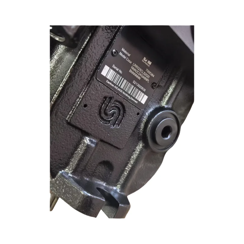
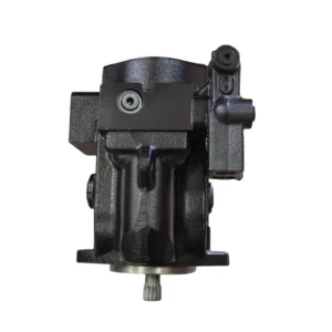
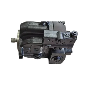


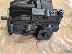

LRR025CLS2020NNN3C2AGA6NPLBNNNNNNN Axial Variable High Pressure Hydraulic Piston Pump KRR KRL LRR025 LRR030 KRR038 KRR045
•
Displacement: The “025” in the model corresponds to a theoretical displacement of 25 mL/r, which is a small-displacement specification and is suitable for medium and high-pressure low-flow working conditions.
•
Working pressure: Rated working pressure 315 bar (31.5 MPa), peak pressure up to 350 bar (35 MPa), with stable high-pressure output capability, suitable for heavy-duty load scenarios.
•
Speed range: Rated speed 1500 rpm, maximum speed 2000 rpm, minimum stable speed no less than 50 rpm, compatible with medium and high-speed continuous operation as well as low-speed high-torque operation.
•
Control mode: Integrated electro-hydraulic proportional variable control and pressure cut-off protection function. The “CLS” mark corresponds to the load-sensitive control logic, which can adjust the displacement in real time according to the system load and adapt to the collaborative working conditions of multiple actuating elements.
•
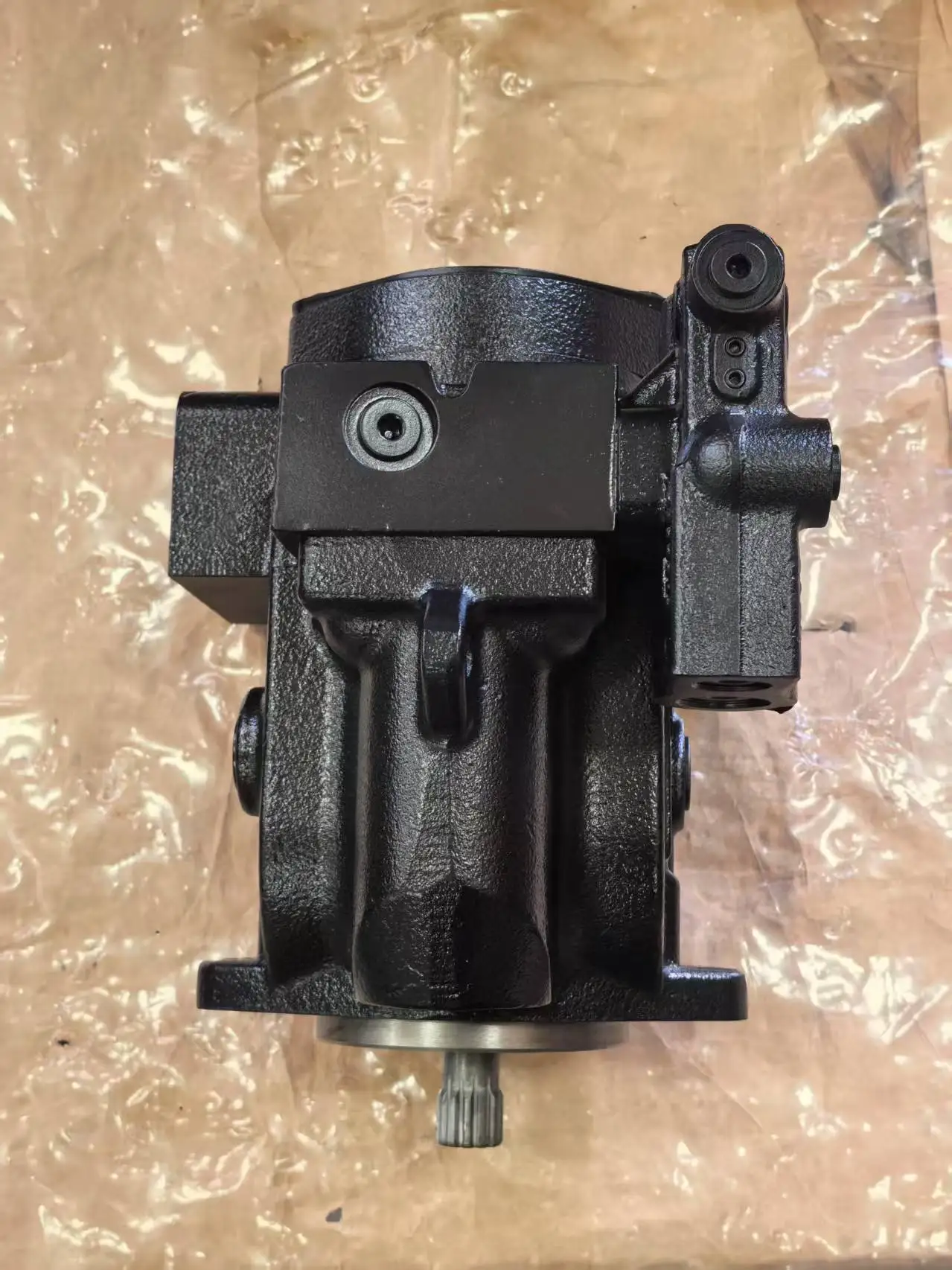
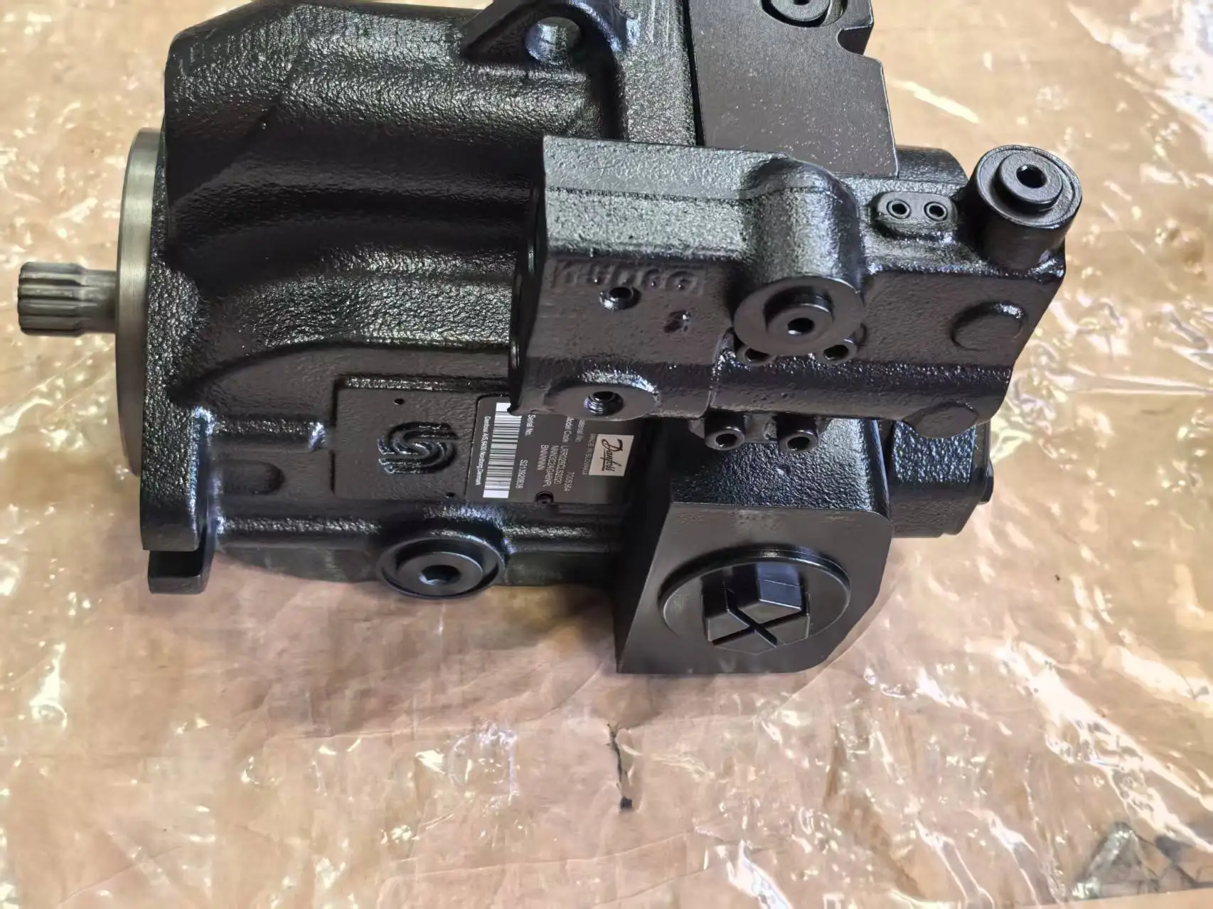
Structural form: Radial plunger structure. The “3C2” marking corresponds to the configuration of a three-column plunger group. It adopts an integral pump body design to enhance structural rigidity.
•
Oil requirements: Anti-wear hydraulic oil with viscosity ranging from 15 to 400 mm²/s is suitable. The working oil temperature range is from -20℃ to 85℃, and the oil cleanliness must reach NAS level 7 (ISO 17/13).
•
Installation and adaptation: The shaft ends are connected by splines, and the shaft diameter complies with the ISO 14688 standard. Flange connection complies with SAE J518B specification. The oil port is arranged on the side and supports horizontal or vertical installation.Ii. Working Principle
This hydraulic pump adopts a radial plunger structure. Its core components include the stator, rotor, plunger, oil distribution shaft and load-sensitive control valve group. During operation, the prime mover drives the rotor to rotate around the oil distribution shaft. Under the combined action of centrifugal force and the internal curve of the stator, the uniformly distributed plungers on the rotor perform reciprocating motion along the radial direction of the rotor. When the plunger rotates with the rotor to the long radius section of the stator’s inner curve, it extends outward. The volume of the sealed cavity formed with the rotor and the oil distribution shaft increases, creating a local vacuum. The oil in the oil tank is sucked into the cavity through the oil suction channel of the oil distribution shaft, completing the oil suction process. When the plunger rotates to the short radius section of the stator’s inner curve, it is squeezed inward and contracts, reducing the volume of the sealed cavity and increasing the oil pressure. The oil is then discharged to the system through the oil distribution shaft’s oil discharge channel, completing the oil pressure process.
The load-sensitive control mechanism collects the system load signal in real time through the pressure sensor. When the load pressure rises, the control valve group adjusts the eccentricity between the stator and rotor, increases the plunger stroke, and the displacement increases accordingly. When the load pressure decreases, the eccentricity reduces and the displacement decreases simultaneously, achieving precise matching of flow and load. The pressure cut-off protection function automatically reduces the displacement to the minimum when the system pressure reaches its peak, preventing overpressure from damaging components.
Iii. Product Features and Advantages
•
Strong high-pressure load-bearing capacity: The high-pressure design with a rated pressure of 315 bar and a peak pressure of 350 bar, combined with the structural advantages of the radial plunger, can stably output high-pressure power in small-displacement scenarios, making it suitable for high-pressure and small-flow hydraulic systems.
•
Excellent low-speed stability: The minimum stable speed is as low as 50 rpm, with no crawling phenomenon during operation, and the torque fluctuation error is ≤±3%. It is particularly suitable for working conditions that require low-speed and high-torque drive, such as winches and slewing mechanisms.
•
High control accuracy: Dual control of electro-hydraulic ratio and load sensitivity, displacement adjustment range is 5%-100%, response time ≤0.2 seconds, can quickly adapt to load fluctuations, and ensure the coordination of multiple actuator actions.
•
Good structural rigidity: The integral cast iron pump body + three-in-one plunger group configuration has excellent impact resistance and vibration resistance. In the bumpy scenarios of construction machinery, the failure rate of the pump body is reduced by more than 40%, and the service life can reach over 8,000 hours.
•
High installation flexibility: Supports both horizontal and vertical installation methods. The side oil port layout is adapted to the pipeline direction of different equipment, and the spline connection can be compatible with various power end output forms.
Iv. Usage Functions and Purposes
1. Usage function
As the power core of the hydraulic system, it converts the mechanical energy of the prime mover (motor, engine) into the pressure energy of the hydraulic oil, providing high-pressure and low-flow oil for the actuating components such as hydraulic cylinders and hydraulic motors, driving the equipment to achieve linear or rotational movements such as rotation, clamping, lifting, and flipping. Through the synergy of load sensitivity and proportional control, dynamic flow distribution and precise pressure regulation are achieved, ensuring the operational efficiency and safety of the system under complex working conditions.
2. Uses
It is widely applied in medium and high-pressure low-flow hydraulic systems, covering fields such as construction machinery, industrial manufacturing, mining machinery, port machinery and special equipment, providing stable power for the high-precision actuators of equipment, especially suitable for scenarios with high requirements for low-speed stability and control accuracy.
V. Applicable Machines and Scenarios
1. Applicable machines
•
Construction machinery: slewing mechanisms of small excavators (6-10 tons), hydraulic winches, and luffing cylinder drive units of crawler cranes.
•
Industrial equipment: Precision hydraulic fixtures, small and medium-sized hydraulic presses (50-100 tons), feed drive systems for metalworking machine tools.
•
Mining and port machinery: Propulsion mechanisms for small mining roadheaders and lifting systems for small port handling equipment.
•
Special equipment: Outrigger cylinder drive for aerial work platforms and rotary power units for hydraulic rotary platforms.
2. Applicable scenarios
It is suitable for working conditions featuring high pressure and low flow rate, low speed and high torque, and coordinated operation of multiple actuating elements, such as precise processing positioning in factory workshops, small equipment rotary operations in construction, small-scale tunneling advancement in mines, and light loading and unloading lifting in ports. It is especially suitable for continuous operation scenarios that have high requirements for equipment control accuracy, operational stability and installation space.
Six. Similar models
This model belongs to the LRR series radial piston hydraulic pump. Similar models are mainly distinguished by displacement, pressure rating and control mode. Common ones include:
•
LRR020CLS2020NNN3C2AGA6NPLBNNNNNNN: 20 mL/r, displacement pressure rated 315 bar, the control method and target model, fit smaller flow of high pressure system.
•
LRR030CLS2020NNN3C2AGA6NPLBNNNNNNN: 30 mL/r, displacement pressure rated 315 bar, as with a series of large displacement model, adaptive flow in high pressure condition.
•
LRR025CLP2020NNN3C2AGA6NPLBNNNNNNN: agree with target type displacement, stress, using the pressure control (CLP), adaptation to demand higher single components of system pressure stability.
•
Similar alternative model: LRM025 series radial piston pump, with the same structure and principle, the peak pressure is increased to 380 bar, suitable for special working conditions of ultra-high pressure and small flow.
Vii. Precautions for Use
•
Oil management regulations: Strictly select anti-wear hydraulic oil with a viscosity of 20-200 mm²/s. It is strictly prohibited to mix oils of different brands or grades. A ≥80 μm screen filter is installed at the oil suction port, and a 10 μm fine filter is added to the return oil line. The contamination degree of the filter element is checked every 300 hours, and the hydraulic oil is replaced and the oil tank is thoroughly cleaned every 1500 to 2000 hours.
•
Installation accuracy requirements: Connect to the prime mover with an elastic coupling. The coaxiality error of the two shafts should be ≤ 0.08mm, and the angular error should be ≤0.3°. The length of the oil suction pipeline should be no more than 1.2 meters, and its diameter should not be less than that of the pump’s oil suction port to prevent excessive oil suction resistance and cavitation. The pipeline connection must be reliably sealed to prevent air from entering.
•
Start-up and operation monitoring: Before the initial start-up, the pump body should be filled with clean hydraulic oil. Manually turn the wheel 5-6 times to confirm there is no jamming. When starting up, run it at low speed (600 rpm) without load for 15 minutes. Once the oil temperature rises above 30℃, gradually increase the load to 30%, 60%, and 100% of the rated pressure. During operation, monitor the oil temperature (30-70℃ is the best, and the maximum should not exceed 85℃) and pressure (it is strictly prohibited to exceed the rated pressure for a long time). If any abnormal noise, vibration or leakage occurs, stop the machine immediately for inspection.
•
Maintenance and care nodes: Check the sealing condition of the shaft seal every 800 hours. When the leakage exceeds 2 drops per minute, the sealing parts should be replaced in time. Disassemble and inspect the friction pairs such as the plunger and the inner curve of the stator every 3,000 hours. If there are scratches on the surface or the wear exceeds 0.02mm, repair or replacement is required. Before long-term shutdown (more than 30 days), drain the oil in the pump or inject anti-rust oil, seal the oil port and cover it with a dust cover.
•
Control parameter setting: The parameters of the load sensitive valve and the pressure shut-off valve must be set by professionals according to the working conditions. It is strictly prohibited to arbitrarily increase the pressure or flow limit values. After replacing the control module, parameter calibration is required to ensure that the control signal is linearly matched with the displacement output and to avoid system shock.


