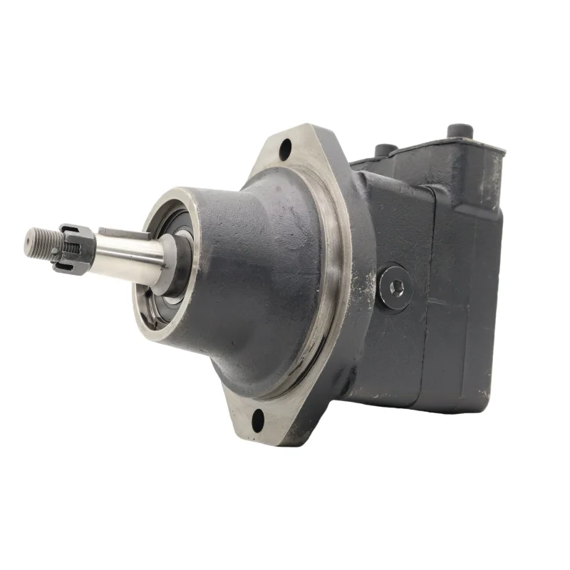
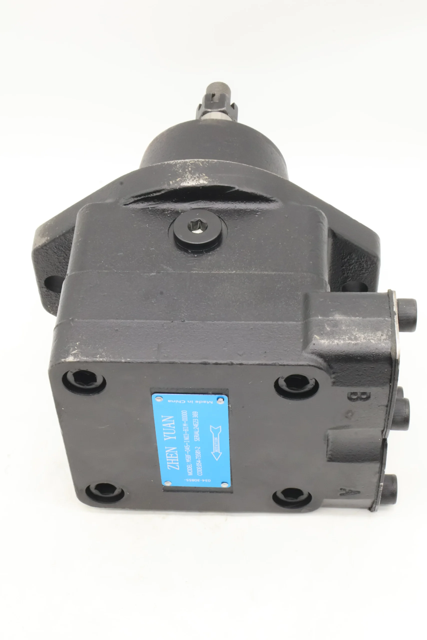


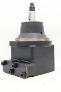

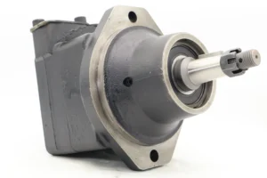


M5 M5A M5AF M5B M5BS M5BF M5ASF Series M5BF-045-1N03-B1M-00000 High Pressure Hydraulic Vane Motor
Basic specifications
Type: M5BF series unidirectional rotating vane motor, 045 indicates nominal displacement 45cc/rev, 1N03/B1M is the installation and connection method, and -00000 is the special function code
Nominal displacement: 45cc/rev (45 milliliters of hydraulic oil output per revolution), theoretical flow rate is approximately 67.5L/min at 1500r/min
Rated pressure: 280bar (28MPa), maximum intermittent working pressure: 320bar, short-term peak value up to 350bar
Speed range: 600-6000r/min, recommended operating speed: 2500-4000r/min, minimum stable speed: ≥600r/min
Rotation direction: Unidirectional clockwise (viewed from the end of the shaft), no reverse rotation
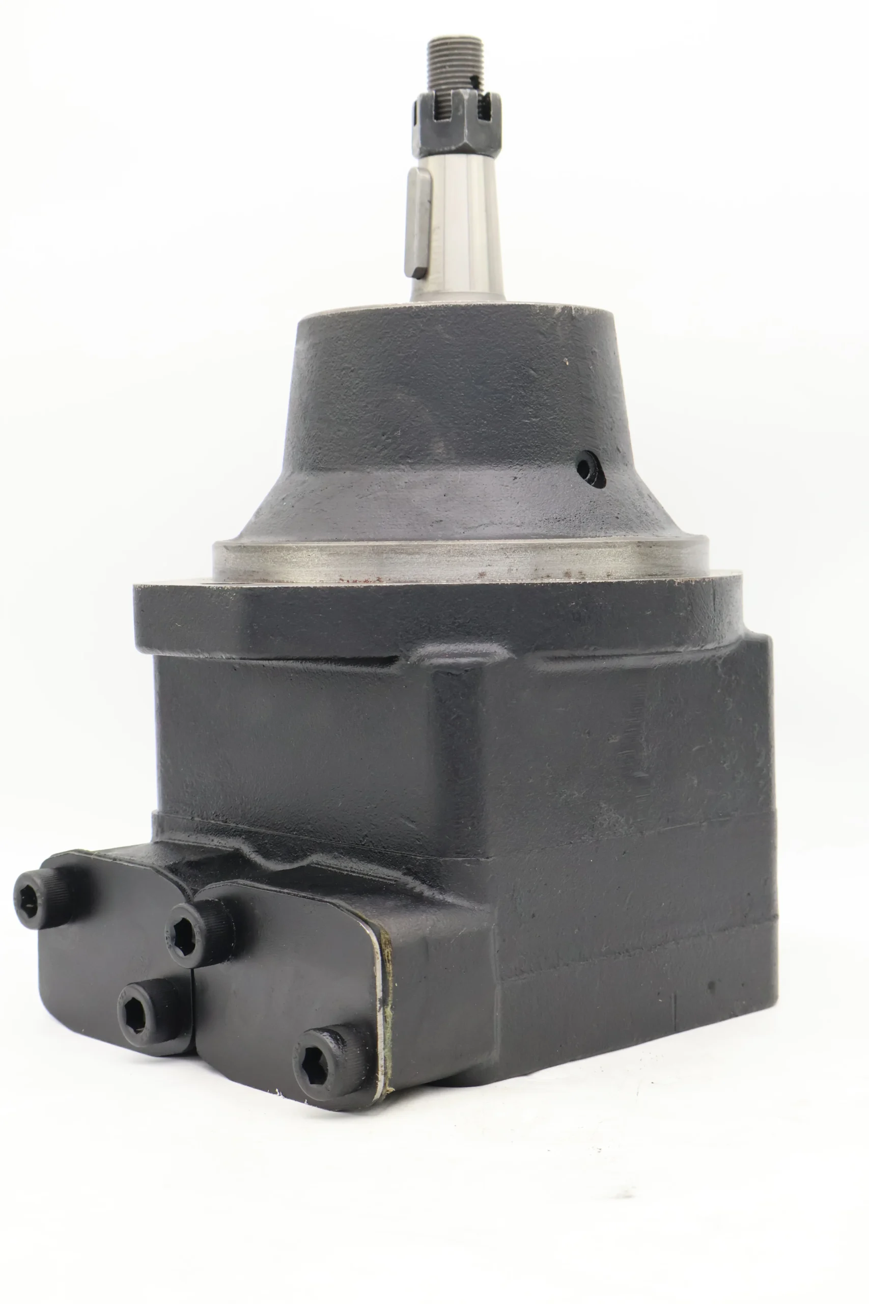
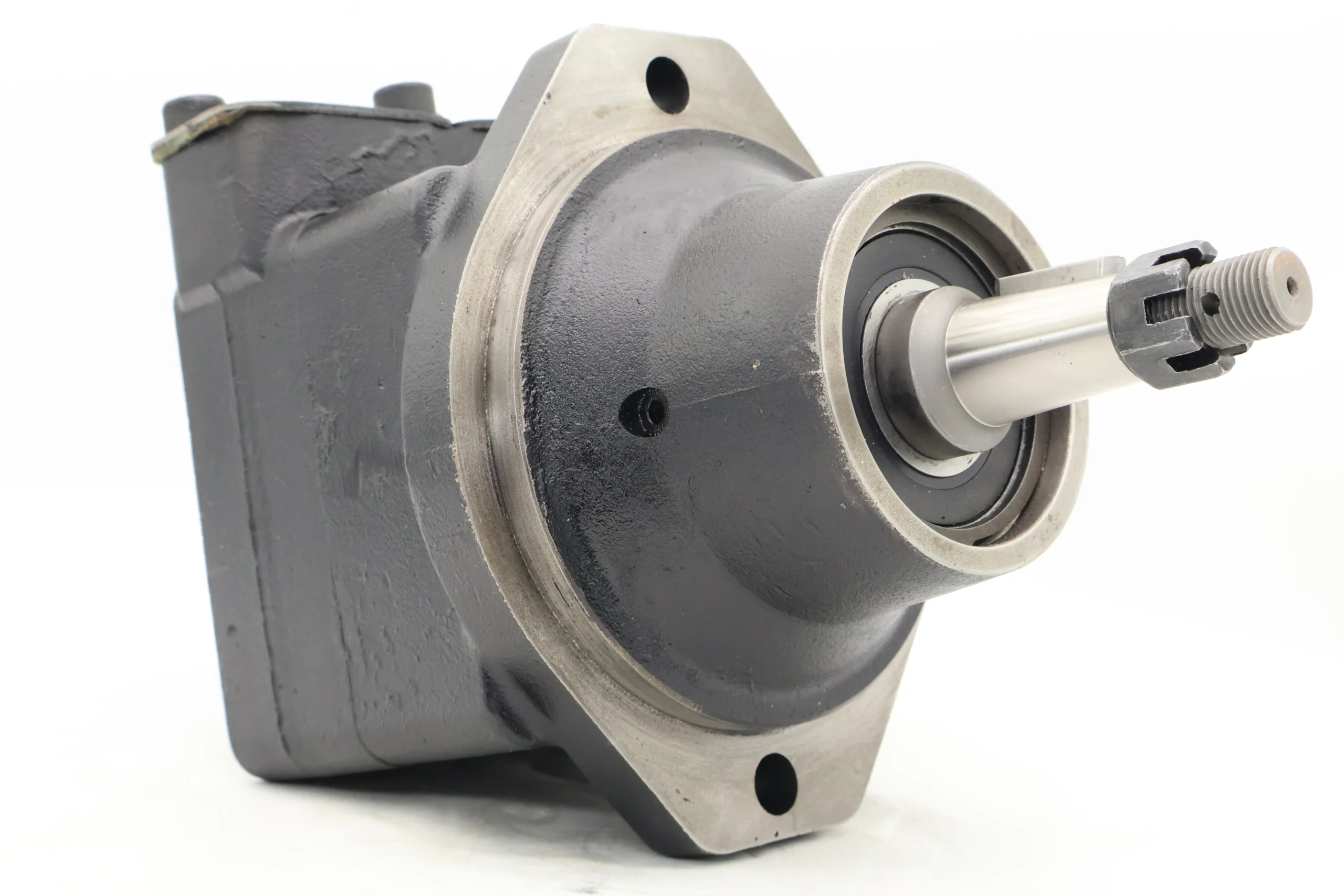
Weight: Approximately 18.5kg (excluding accessories), compact structure, and high power density
Working parameters
Volumetric efficiency: ≥90% (under rated conditions), with low energy conversion loss
Overall efficiency: ≥80%, with highly efficient comprehensive performance
Applicable medium: Anti-wear hydraulic oil (viscosity index ≥90); it is recommended to use L-HM46 or L-HV46 hydraulic oil
Medium viscosity: 10-300mm²/s, optimal working viscosity: 20-60mm²/s
Medium temperature: -10℃ to +70℃, recommended working temperature: 30-55℃. Avoid high temperatures, which can cause a decrease in oil viscosity
Noise level: <70dB (A), smooth operation, and good noise control
Oil cleanliness: ISO 4406 19/16 grade. A 10μm precision filter must be installed to protect the precision componentsIi. Working Principle
Core working mechanism of vane motor
Basic structure
It is composed of a stator (fixed housing), a rotor (rotating shaft), 12 evenly distributed blades, front and rear end covers, and an oil distribution plate
The rotor is eccentrically installed in the stator (with an eccentricity of e), and the blades can freely slide in the radial slots of the rotor
The bottom of the blade is connected to the high-pressure oil chamber through a special channel to ensure that the blade always closely adheres to the inner wall of the stator
Principle of torque generation
High-pressure oil enters through the oil inlet and acts simultaneously on the bottom of the blades and the working chamber
The oil pressure at the bottom of the blade causes the blade to press against the inner wall of the stator, forming a sealed working chamber
Due to the eccentricity of the rotor, the extended lengths of different blades at the same time are different, resulting in variations in the compressed area
The extended length of blade 3 is greater than that of blade 1, and the force-bearing area S3 is greater than S1, resulting in a clockwise torque difference M=(P×S3-P×S1)×L (where P is the oil pressure and L is the lever arm).
The rotor continuously rotates under the action of torque, overcoming the load resistance, and outputs mechanical energy
Oil flow direction
High-pressure oil → Oil inlet → Oil distribution plate window → bottom of the blade and working chamber → Push the blade → rotor rotation
Low-pressure oil → Working chamber → another window of the oil distribution plate → oil outlet → return to the oil tank
The motor is equipped with a built-in balance valve to ensure that the bottom of the blades always maintains high pressure, allowing for reliable start-up even under low-speed conditions
Iii. Product Features and Advantages
1. Outstanding startup and dynamic performance
High starting torque: The starting torque efficiency is ≥78.3% (under 100bar pressure), allowing for direct starting under load without the need for no-load acceleration
Fast response: It features excellent emergency start and stop characteristics, making it suitable for application scenarios that require frequent start-stop and reversing
Stepless speed regulation: By simply adjusting the flow rate, continuous and smooth regulation from 0 to the maximum speed can be achieved, with high control accuracy
Low torque ripple: The 12-blade design keeps the torque fluctuation within ±1.5%, providing extremely smooth output and making it suitable for precision drive
2. Structural and reliability advantages
Compact design: Small in size, light in weight, and high in power-to-mass ratio, suitable for installation environments with limited space
Long service life: The blades, rotor, and stator are made of special wear-resistant materials and designed for pressure balance, with an average mean time between failures of over 5,000 hours
Built-in protection: Integrated dynamic brake valve, which can stop smoothly and reduce the risk of cavitation, extending service life
Anti-pollution ability: Compared with plunger motors, it is less sensitive to oil contamination and is suitable for harsh working environments
3. Energy conservation and economy
High-efficiency energy conversion: Maintain high efficiency over a wide range of rotational speeds and reduce system energy consumption
Easy maintenance: Modular structure makes it easy to disassemble and repair, and key components can be replaced separately
Flexible installation: Multiple installation flange and shaft extension forms are available to meet the interface requirements of different equipment
High cost performance: Among similar high-voltage motors, it has a moderate price, stable performance and low long-term operating costs
Iv. Usage Functions and Purposes
Core functions
Convert the pressure energy of the hydraulic system into mechanical energy to provide rotational power
Precisely control the rotational speed and torque to meet the requirements of different working conditions
It can be coordinated with the control system to achieve an automated production process
Main application fields
Heat dissipation system for construction machinery
Drive the cooling fans of construction machinery engines such as excavators, loaders, and bulldozers
The fan drive of the hydraulic system oil cooler ensures the stability of the system temperature
It provides reliable heat dissipation in high-temperature environments to ensure the continuous operation of the equipment
Industrial cooling system
Fan drive for the cooling system of large mechanical equipment
Power sources for the cooling devices of hydraulic stations and lubrication stations
The heat dissipation system for metallurgical and mining equipment is suitable for harsh working conditions
Agricultural machinery
Engine cooling systems for harvesters and tractors
The ventilation system drive of the grain drying equipment
Environmental control system for livestock machinery
Other fields
Generator set cooling fan drive
The heat dissipation system of the machinery on the ship deck
Large fan drive for air conditioning system (requires a matching reducer)
V. Applicable Machines and Scenarios
1. Typical applicable machines
Excavator cooling system
It is particularly suitable for 6-15 ton excavators, such as the EX1200-6 and ZX60 models of a certain brand
As a fan motor, it directly drives the cooling fan to ensure the temperature stability of the engine and hydraulic system under high-intensity operation
It can still provide stable air volume under compound action and heavy load conditions, protecting the equipment from overheating damage
Loader cooling system
It is applicable to 3-5 ton class loaders, such as the ZL50 series
Drive the fan of the transmission oil cooler and the fan of the hydraulic oil cooler to prevent the system efficiency from decreasing due to excessively high oil temperature
Provide reliable heat dissipation guarantees in construction sites with heavy dust and harsh environments
Industrial hydraulic station
Cooling units suitable for various large-scale hydraulic systems
Drive cooling fans in the hydraulic systems of metallurgical and forging equipment to maintain the system’s operating temperature within the optimal range of 30-55℃
Ensure the stability of the hydraulic oil viscosity to enhance system efficiency and component lifespan
2. Characteristics of applicable scenarios
Construction machinery and industrial equipment that require reliable heat dissipation, especially under high-temperature and high-load working conditions
For compact equipment with limited space, the M5BF series’ feature of small volume and high torque is particularly suitable
Low-noise working environments are required, such as urban construction machinery and indoor industrial equipment
Cooling systems that require frequent start-stop operations, such as construction machinery that operates intermittently
The hydraulic system pressure is stable in medium and high-pressure application scenarios ranging from 200 to 300bar
Six. Similar models
1. Different specifications and models of the same series
M5BF-028: Displacement 28cc/rev, lighter in weight (about 16kg), suitable for small equipment and cooling systems with lower flow requirements
M5BF-060: Displacement 60cc/rev, with greater output torque, suitable for large construction machinery and cooling systems that require high air volume
M5BS-045: With the same displacement as M5BF-045, but with SAE B standard installation flanges, it is suitable for equipment with different interface requirements
2. Different series models of the same type
M5B-045: Basically the same as M5BF-045, but in the standard installation form (ISO 3019-2 100/A2), not specifically for fan drive
M5AF-045: Another variant of the M5 series, featuring different shaft extensions and sealing configurations, suitable for special application scenarios
M4C-045: Another classic series of the same brand, it is more economical in price and suitable for applications with limited budgets, but its performance is slightly lower than that of the M5 series
3. Domestic alternative products
Domestic M5BF series substitutes: such as the BF045 series produced by a certain brand, with similar performance parameters and more economical prices, are suitable for the domestic maintenance market
Other brands of 45cc/rev vane motors, such as the A2F series (fixed displacement motors) and YMD series, can be used as substitutes under specific conditions
Vii. Precautions for Use
1. Installation points
Direction confirmation
The one-way motor must be installed in the specified direction (rotating clockwise), and the oil inlet and return ports must not be reversed
The oil inlet is connected to the system pressure oil, and the oil outlet is connected to the oil tank. Otherwise, it may damage the motor or cause system failure
Fixation and connection
The installation plane must be flat (flatness < 0.1mm), and the fixing bolts should be evenly tightened to prevent the shell from deforming and affecting the movement of the blades
The motor shaft and the load should be connected by an elastic coupling. Rigid connection is strictly prohibited
Coaxiality error is less than 0.05mm, angular deviation is less than 0.5°, reducing vibration and bearing load
Pipeline configuration
The diameter of the oil inlet pipe is ≥25mm, and the length is < 2m, to reduce the oil suction resistance
The diameter of the oil outlet pipe is ≥20mm to ensure smooth oil return
The suction pipeline must be well sealed to prevent air from entering the system and causing cavitation
2. Startup and Operation management
Startup program
Check the oil level in the fuel tank (≥ 200mm above the suction port) and the oil temperature (≥-10℃)
Manually turn the wheel 2 to 3 times to ensure there is no jamming
Loosen the exhaust plug, jog the starter motor to the exhaust, and then tighten it after continuous oil output
Start the machine without a load and run it for 3 to 5 minutes to observe if there are any abnormal noises or leaks
Gradually load. It is strictly prohibited to directly load the cold machine to full load (each pressure increase ≤30% of the rated pressure, with an interval of ≥2 minutes).
Operation monitoring
Oil temperature: Normal operating temperature is 30-55℃. If the temperature exceeds 70℃, the machine should be shut down to check the cooling system
Pressure: Not exceeding the rated value (280bar), peak not exceeding 320bar, and cumulative time less than 10 minutes per hour
Noise: Smooth operation <70dB. Abnormal noise (>75dB) indicates possible wear or cavitation, and the machine should be stopped immediately
Leakage: Slight seepage (<5 drops per minute) is allowed. If the leakage increases, timely maintenance is required
3. Maintenance and care
Daily inspection
Check the oil level, temperature, noise and leakage conditions every shift, and record the operating parameters
Check if the connecting bolts are loose and tighten them in time
Clean the surface of the motor to prevent the accumulation of oil stains from affecting heat dissipation
Regular maintenance
Every 250 hours: Check the pressure difference of the filter (<0.15MPa), and replace the filter element if necessary
Every 500 hours: Check the contamination level of the oil (≤ISO 4406 19/16 grade), and take samples for testing if necessary
Every 1000 hours: Change the hydraulic oil and clean the oil tank and filter at the same time
Every 2000 hours: Conduct a comprehensive disassembly and inspection to measure the wear of the blades, rotor and stator. Replace the worn parts if necessary
Oil Product Management
Hydraulic oils of different brands must not be mixed to prevent the reaction of additives and the formation of sediment
In cold regions, low-viscosity hydraulic oil (such as L-HV series) should be used to ensure low-temperature starting performance
Regularly test the viscosity and acid value of the oil to ensure they meet the usage requirements
4. Special Precautions
Prevent dry running
It is strictly prohibited to start the motor without oil. Even a short period of dry running will cause severe wear on the blades and stator
After a long period of inactivity, when restarting the motor, clean hydraulic oil should be filled into it
Prevent cavitation
Ensure that the oil suction pipeline is well sealed to prevent air from entering the system
The oil suction height should be less than 500mm, and it is recommended to be less than 300mm to reduce the oil suction resistance
When the oil temperature is too low (<10℃), run it no-load for 15 minutes first to increase the oil temperature before loading
Load matching
It is strictly prohibited to operate beyond the rated pressure and speed; otherwise, the service life will be significantly shortened
Avoid frequent overload impacts and protect the precision mating parts inside the motor
Shutdown protection
Before shutting down, the oil should be unloaded to a low pressure (<20bar) and run for 3 to 5 minutes. Only when the oil temperature drops below 60℃ should the power be cut off
When the motor is not in use for a long time, the oil inlet and outlet ports should be sealed to prevent foreign objects from entering the interior


